Improving Surgical Grasper
Performance
Dominic Paul Jones
School of Mechanical Engineering
University of Leeds
Submitted in accordance with the requirements for the degree of
Doctor of Philosophy
The candidate confirms that the work submitted is his/her own, except where work which has formed part of jointly-authored publications has been included. The contribution of the candidate and the other authors to this work has been explicitly indicated below. The candidate confirms that appropriate credit has been given within the thesis where reference has been made to the work of others. In all papers listed below, the primary author completed all experimental studies, evaluation of data and preparation of publications. All authors contributed to proof reading of the articles prior to publication.
Papers contributing to this thesis:
• Jones, DP; Wang, H; Alazmani, A; Culmer, PR.A soft multi-axial force sensor to
assess tissue properties in Real-Time. In 2017 IEEE/RSJ International Conference
on Intelligent Robots and Systems Proceedings (pp. 5738-5743). IEEE.
• Jones, DP; Jaffer, A; Alazmani, A; Biyani, CS; and Culmer, P., 2018. Analysis
of mechanical forces used during laparoscopic training procedures. Journal of
Endourology.
• Jones, DP; Kow, JW; Alazmani, A; and Culmer, P., 2018. Computational
De-sign Tools for Soft Inductive Tactile Sensors. In IEEE International Conference
on Biomedical Robotics and Biomechatronics (BioRob), 2018 7th . IEEE.
For the above Papers, all experimental work and data analysis was completed by myself, with the co-authors responsible for reviewing the papers.
• Wang, H., Jones, D., de Boer, G., Kow, J., Beccai, L., Alazmani, A. and Culmer, P., 2018. Design and Characterization of Tri-axis Soft Inductive Tactile Sensors. IEEE Sensors Journal.
For this paper, H Wang was responsible for the majority of experimental work and data processing, I was responsible for the design and experimentation of the final validation study. Myself and all other co-authors were responsible for reviewing the paper.
This copy has been supplied on the understanding that it is copyright material and that no quotation from the thesis may be published without proper acknowledgement.
Dominic Paul Jones June 2019
First, I would like to thank my two supervisors, Pete Culmer and Ali Alazmani, for their support and advice over the past three years. Between them they have always helped me to find the motivation to put in that little extra to push me to greater heights.
To Shekhar, Ata, and the staff at Leeds Teaching Hospitals, thank you for your insights, assistance, and efforts to expand the research through your collaboration and expertise in the surgical field.
Next to my family and friends for always being there to keep me calm and for your unwavering support over the years. Without me talking nonsense at you half of my problems would never have been solved.
Finally to Ellie, my wonderful fiancée, without whom none of this would have been possible. Without your love and support (and copious amounts of cake) I would never have lasted this long. You are my inspiration, motivation, and my best friend.
Minimally invasive techniques play a vital and increasing role in modern surgery. In these procedures, surgical graspers are essential in replacing the surgeon’s fingertips as the main manipulator of delicate soft tissues. Current graspers lack haptic feedback, restricting the surgeon to visual feedback. Studies show that this can frequently lead to morbidity or task errors due to inappropriate application of force. Existing research has sought to address these concerns and improve the safety and performance of grasping through the provision of haptic feedback to the surgeon. However, an effective method of grasping task optimisation has not been found.
This thesis explores new sensing approaches intended to reduce errors when manipulating soft tissues, and presents a novel tactile sensor designed for deployment in the grasper jaw. The requirements were first established through discussion with clinical partners and a literature review. This resulted in a conceptual approach to use multi-axis tactile sensing within the grasper jaw as a potential novel solution.
As a foundation to the research, a study was conducted using instrumented graspers to investigate the characteristics of grasp force employed by surgeons of varying skill levels. The prevention of tissue slip was identified as a key method in the prevention of grasper misuse, preventing both abrasion through slip and crush damage. To detect this phenomena, a novel method was proposed based on an inductive pressure sensing system. To investigate the efficacy of this technique, experimental and computational modelling investigations were conducted. Computational models were used to better understand the transducer mechanisms, to optimise sensor geometry and to evaluate performance in slip detection. Prototype sensors were then fabricated and experimentally evaluated for their ultimate use in slip detection
within a surgical grasper. The work concludes by considering future challenges to clinical translation and additional opportunities for this research in different domains.
List of figures xv 1 Introduction 1 1.1 Project Aim . . . 3 1.1.1 Research Objectives . . . 3 1.2 Thesis Overview . . . 4 2 Literature Review 7 2.1 Minimally Invasive Surgery . . . 8
2.2 Soft Tissue Properties . . . 8
2.2.1 Biological Constitution of Soft Tissues . . . 9
2.2.2 Electrical Properties . . . 11
2.2.3 Electrochemical Properties . . . 12
2.2.4 Mechanical Properties . . . 12
2.3 Current Surgical Graspers . . . 13
2.3.1 Placement of sensors . . . 14
2.3.2 Tissue-tool Interaction Pressures in Grasping Tasks . . . 16
2.4 Mechanical Measurement in a Grasping Environment . . . 16
2.4.1 Techniques in open surgery . . . 17
2.4.1.1 Mechanics of Fingertip Sensing . . . 17
2.4.2 Resistive sensors . . . 18
2.4.2.2 Piezoresistive Sensors . . . 20
2.4.3 Capacitive Sensors . . . 22
2.4.4 Computer Vision . . . 23
2.4.5 Optical Fibre Sensors . . . 25
2.4.6 Other Transducer Methods . . . 26
2.4.6.1 Hall Effect based Sensors . . . 26
2.4.6.2 Inductive Tactile Sensors . . . 27
2.5 Summary of Literature . . . 29
3 An Analysis of Grasping Forces in MIS 33 3.1 Introduction . . . 34
3.1.1 Chapter Objectives . . . 34
3.2 Recording Surgical Grasping Forces . . . 35
3.3 Materials and Methods . . . 35
3.3.1 Instrumented Laparoscopic Graspers . . . 35
3.3.1.1 Grasper Mechanism Effect . . . 36
3.3.2 Experimental Procedure . . . 38
3.3.3 Data Processing . . . 39
3.4 Results . . . 40
3.5 Discussion . . . 44
3.6 Chapter Summary . . . 45
4 Investigating Methods of Applying Sensing to Improve Grasper Performance 47 4.1 Introduction . . . 48
4.1.1 Chapter Objectives . . . 48
4.1.2 Sensing Applications for Grasper Usage Optimisation . . . 49
4.1.2.1 Normalised Stress Rate of Compression . . . 49
4.1.2.2 Tissue Slip Prevention . . . 50
4.2 Materials and Methods . . . 51
4.2.2 Experimental Equipment . . . 53
4.2.3 Experimental Methodology . . . 57
4.2.3.1 Normalised Stress Rate of Compression . . . 57
4.2.3.2 Tissue Slip Prevention . . . 57
4.3 Results . . . 58
4.3.1 Normalised Stress Rate of Compression . . . 58
4.3.2 Tissue Slip . . . 60
4.4 Discussion . . . 61
4.5 Chapter Summary . . . 63
5 Investigating a Novel Sensing Method to Improve Laparoscopic Grasping Tasks 65 5.1 Introduction . . . 66
5.1.1 Chapter Objectives . . . 67
5.2 Working Principle . . . 68
5.3 Methods . . . 70
5.3.1 Sensor Response Calculation . . . 70
5.3.1.1 Computational Modelling . . . 70 5.3.2 Experimental Configuration . . . 72 5.3.3 Parametric Study . . . 73 5.3.3.1 Vertical Displacement . . . 74 5.3.3.2 Horizontal Displacement . . . 75 5.3.3.3 Target Rotation . . . 75
5.3.3.4 Target Size Optimisation . . . 76
5.4 Results . . . 76
5.4.1 Simulation Data . . . 76
5.4.2 Experimental Validation . . . 77
5.4.3 Target Size Optimisation . . . 79
5.5 Discussion . . . 81
6 Computational Optimisation of Inductive Tactile Sensors in 3D 85 6.1 Introduction . . . 86 6.1.1 Chapter Objectives . . . 86 6.2 Methods . . . 86 6.2.1 Lumped 3D Model . . . 87 6.2.2 Full 3D Model . . . 88 6.3 Results . . . 91 6.3.1 Lumped Simulations . . . 92 6.3.2 Full 3D Model . . . 96 6.4 Discussion . . . 98 6.5 Chapter Summary . . . 101
7 A Sensor for Slip Detection within a Grasper Jaw 103 7.1 Chapter Objectives . . . 104
7.2 Sensor Fabrication . . . 104
7.3 Sensor Characterisation . . . 105
7.3.1 Experimental Configuration . . . 105
7.3.2 Sensor Performance Evaluation . . . 105
7.4 Slip Evaluation . . . 107
7.4.1 Experimental Methods . . . 108
7.4.2 Results . . . 109
7.5 Grasping Sensor Prototype . . . 114
7.5.1 Performance Evaluation . . . 116
7.6 Discussion . . . 118
7.7 Chapter Summary . . . 121
8 General Discussion and Conclusions 123 8.1 Assessment of Research Objectives . . . 123
8.2 General Discussion . . . 125
8.3.1 Grasping Task Optimisation . . . 129 8.3.2 Simulation Advancements . . . 130 8.4 Concluding Remarks . . . 131
1.1 A schematic of abdominal MIS, indicating several key tools: (a) Trocar, (b) Grasper, (c) Insufflated Abdomen, and (d) Laparoscope . . . 2
2.1 Examples of Surgical grasper tips, (a) Short fenestrated and (b) Fine toothed forceps (Surgical Innovations, Leeds, UK); and (c) Hammond’s soft atrau-matic grasper, from [1] . . . 9 2.2 Diagram of connective tissue structure, indicating the matrix of collagen and
elastin. Fibroblast cells are also present within the matrix, from . . . 10 2.3 Collagen microstructures of different tissues: a) Tendon, displaying parallel
orientation and b)Stroma of the small intestine, showing a web-like structure, from [2] . . . 11 2.4 The influence of deformation speed on the viscoelastic properties of tendon,
showing increased elastic modulus at increased speed. Adapted from [3] . . 13 2.5 Indication of the ’safe’ grasping forces bounded by slip and crush forces,
adapted from [4] . . . 14 2.6 Schematic of the location of various mechanoreceptors in the fingertip, from
[5] . . . 18 2.7 (a) Example of a 1D strain gauge, (b) Stewart Platform arrangement (labelled
Force/Torque Sensor) [6], (c) The Maltese Cross arrangement [7] . . . 19 2.8 Takashi’s piezoresistive triaxis tactile sensor: (a) Schematic indicating silicon
beams, (b) the bridge used for measurements [8], and (c) photo of the full sensor design [9] . . . 21
2.9 (a) Li’s triaxis tactile sensor [10]; (b) Operating principle of Li’s sensor [10] 22 2.10 (a) Schematic of a Capacitive tactile array, indicating two layers of
perpen-dicular electrodes, from [11], and (b) Multiaxis capacitive tactile sensing principle, from [12] . . . 23 2.11 (a) Bristol’s TacTip and internal view of displacement markers [13], (b)
Gelsight sensor and shear measurement markers [14] . . . 24 2.12 (a) Principles of the fibre Bragg grating (b) indicating the absorption
wave-length change under stress, from [15] . . . 25 2.13 Wang’s MagOne, indicating the applied force deforming the sensor, and
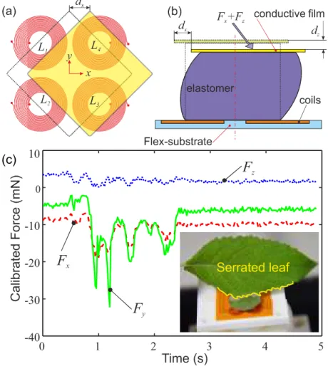
therefore the sensed magnetic field, from [16] . . . 27 2.14 Working principles of Wang’s three axis SITS (a) target movement and (b)
Elastomer deformation; and (c) SITS achieving mN precision under contact with a leaf. . . 28
3.1 A photo of the instrumentation module of the grasper, indicating the key components . . . 36 3.2 Schematic diagram of the grasper mechanism used to calculate the tip force:
Ft - Tip Force,Lj- Jaw Length,Θ- Jaw angle,Θ0- Jaw Angle Offset,LA,B
-Mechanism Linkage Length . . . 37 3.3 Example grasp data obtained by the instrumented graspers. The upper and
lower bounds of calculated pressure (rangeing between 1/3 and 2/3 of the face) are indicated. . . 39 3.4 The test setup in use, showing the simulated environment and positioning of
the participants . . . 40 3.5 Example of idealised Grasping data, not from experimental use. Indicates the
Peak Force (FMAX), average force (FRMS) and the force threshold at which
grasps were detected . . . 41 3.6 Example grasp traces for (a) Novice, (b) Intermediate, and (c) Expert
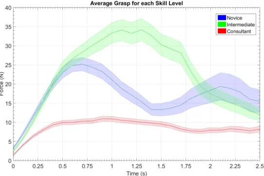
partici-pants . . . 41 3.7 The average grasp profile for each training level±SEM . . . 42
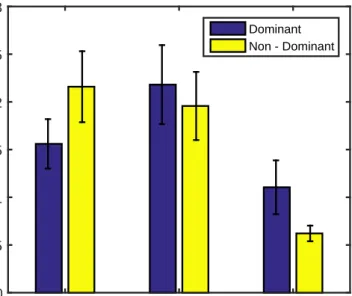
3.8 MeanPMAX andPRMSseparated by experience level . . . 42
3.9 Mean peak pressures for each task, separated by experience level . . . 43 3.10 Average maximum pressure±95% confidence interval for each training level 43
4.1 Parameters calculated from the compression tests. ˙¯θ = Normalised Stress
Rate of Compression,∆σ = Normalised Stress Relaxation . . . 51
4.2 The sectioning method of the (a) colon and (b) Ureter samples . . . 52 4.3 Diagram of the simulated grasping Environment: A -Load Cells, B - Tissue
Sample, C - 3D Printed Grasper Face, and D - SMAC Linear Actuator . . . 54 4.4 Schematic diagram of the controlled grasping system . . . 55 4.5 Flowchart of the control method of the simulated grasping system. . . 56 4.6 Example presure and displacements data from a single colon sample (a)
Grasp 1 (b) Grasp 5 . . . 59 4.7 NSRc vs Relaxation for all grasps recorded for (a) Colon and (b) Ureter. The
regression fit for the full dataset is shown, with anomalous readings indicated by the green box . . . 59 4.8 Normal and Shear forces alongside the calculated coefficient of friction,µ.
The point of slip,µslip. . . 61
4.9 Mean coefficient of frictionµ±SDfor each (a) loading case and (b) speed.
No significant difference is observed (p<0.05 in all cases) . . . 62
5.1 A two-axis SITS. Two inductance coils are positioned below a copper target and silicone elastomer to detect forces in thezandxaxes. . . 67 5.2 Working principles of the single and multi axis SITS. (a) Magnetic field
coupling between the coil and copper target: Shaded region = eddy cur-rent density in target, contours = Field strength; (b) Schematic of target displacement in a 2D SITS with a (c) side view of elastomer deformation . 69
5.3 Diagram of the geometry of the computational simulation. The diagram indicates a half of the simulated two coil cross-section. Each coil was repre-sented by two 2×12 arrays of wires separated by a 2.2mm gap representing the centre of the coil. Each wire section was modelled as a rectangle of dimensions 100 µm ×35 µm. One half of each coil had current directed into the plane, while the opposing side current out of the plane. . . 71 5.4 a) The experimental test platform used to evaluate the 2-axis SITS and the
inductive coil pair used in the system. b) Operation principle of the TI LDC1614. Each channel is operated sequentially, such that only one coil is activated at any one time. . . 73 5.5 Indication of the parameters of target movement in a two axis soft inductive
tactile sensor (indicated in Figure 5.1). Parameters: dv = vertical target displacement;dh= horizontal target displacement;α;w= target width;C1,2
= Coil 1 & Coil 2;Lc1,2= Inductance C1 & C2 . . . 74 5.6 The magnetic field generated by coil 2 during sequential activation under
the test conditions shown in Fig. 5.5. The magnetic field is morphed depen-dent on the displacement and rotation of the target. Gradient lines indicate magnetic vector potential perpendicular to the plane (Wb/m)5.5. . . 77 5.7 Percentage change of inductance (∆L/L0) for a) Vertical Movement, b)
Horizontal Movement, and c) target rotation. Overall outputs for d) Vertical Movement (Eq.5.2) and e) Horizontal Movement (Eq.5.1). f) The error in shear induced by the rotation. . . 78 5.8 Inductance change ((Lc1−Lc2)/L0, and(Lc1+Lc2)/L0) with varying
hori-zontal and vertical target placements . . . 81
6.1 Schematic of the lumped model simulation, where w = Target Width, mm; D = Target Depth, mm; dx,y,z = Target Displacement, mm; rx,y,z = Target
6.2 Diagram of the (a) Circular and (b) square spiral coils. (c) The 3D model simulation of the circular planar spiral coils, whereCsep= Planar Separation, mm . . . 90 6.3 Comparison of the simulations to an experimentally validated inductance,
indicating higher inductance in the validation coil . . . 91 6.4 Results of the shape variation study: dxNormal (a) and Shear (b),dy Normal
(c), anddzNormal (d) . . . 93
6.5 Results of the Length variation study:dxNormal (a) and Shear (b),dyNormal (c), anddzNormal (d) . . . 94
6.6 Results of the Width variation study: dxNormal (a) and Shear (b),dyNormal (c), anddzNormal (d) . . . 95
6.7 Results of the Rotation study: dxNormal (a) and Shear (b),dyNormal (c), anddzNormal (d) . . . 96
6.8 (a) Comparison of the inductance change between square and circular 7mm coils, spaced at 0.1, 1, and 3 mm; and (b) The magnetic Field Strength (Tesla) 98 6.9 Schematic indicating the geometric parameters of the elastomer which may
help prevent rotation: Elastomer Width (Wela) and Thickness (Tela) . . . 100 7.1 a) The experimental test platform used to calibrate and characterise the 2-axis
SITS; and (b) Scanning method of the calibration . . . 106 7.2 Five cycles of the Normal (a) and Shear (b) loading repeatibility test; and
Hysteresis in Normal (c) and Shear (d) axes of the sensor . . . 107 7.3 (a) Schematic of the friction testing setup, indicating the actuation cycle (1.
Loading, 2. Shear, 3. Unloading, 4. Return to starting position); and (b) Photo of the clamped hydrogel sample . . . 108 7.4 Example plots of the force and Coefficient of Friction (Mean±SD) (a)
Load-ing Phase, (b) Shear Phase, (c) UnloadLoad-ing Phase. The slip point (dµ/dt <0),
Forces at Slip (FX Z,slip) and Friction at Slip (µslip) are indicated. . . 109
7.5 Mean shear (FX,slip,blue) and (FZ,slip,red) force profile±SD, separated by condition. . . 111
7.6 Mean Friction Coefficient (µX,slip) profile±SD, separated by condition. . . 112
7.7 (a) Mean values ofFX,slip±95%CI; and (b) Mean values ofFZ,slip±95%CI 113 7.8 Mean values ofµslip±95%CI . . . 114 7.9 (a) Schematic of the miniaturised coil, indicating coil and target sizes; and
(b) The manufactured prototype, with the sensor mounted on a toothless 5 mm laparoscopic grasper (Epix, Applied Medical) . . . 115 7.10 Test equipment for the performance evaluation of the prototype sensor . . . 117 7.11 Force data from two typical grasps from the (a) Compression and (b) Pull tests118 7.12 Indicaton of the target rotation under compression in the grasper face . . . . 119 7.13 Normal force and inductance range variations over a 0.7 mm target
Nomenclature
MIS Minimally Invasive Surgery
ECM Extracellular Matrix
SITS Soft Inductive Tactile Sensor
ANOVA Analysis of Variance
NSRc Normalised Stress Rate of Compression, ˙¯σ
Introduction
MIS was originally introduced in 1983 [17] and has since become a staple technique around the world. Rather than a single long incision to open the operating site, several smaller incisions (typically 10-20mm long) are made at specific points to allow access the abdominal cavity. The smaller incisions assist in a reduced recovery time, as well as reduced scarring to the patient [18]. Several tooling ports, or trocars, are inserted through the incisions to offer sealable access points for the tools to pass through [19]. The abdomen is then insufflated with CO2to provide extra working space for the surgeon. A laparoscope and several long
thin tools are then passed through the trocars (Figure 1.1) to provide vision and manipulation at the operating site. Graspers are a key instrument used to manipulate and hold tissue in MIS procedures, in essence replacing the surgeon’s fingertips. However, the mechanical nature of these tools coupled with the reducing size of the end effectors amplify the pressures applied to the grasped tissue.
While generally accepted as a superior method for reducing surgical damage, there are some disadvantages. The instrumentation used prohibits the perception of forces, velocities, and displacements of the tissues and the proprioception required for motor performance is distorted [20]. Both manual and telerobotic tools also suffer from losses of haptic feedback to the surgeon, thus increasing the likelihood of grasper misuse [21].
(b)
(c)
(d)
(a)
Fig. 1.1 A schematic of abdominal MIS, indicating several key tools: (a) Trocar, (b) Grasper, (c) Insufflated Abdomen, and (d) Laparoscope
The steep learning curve required to overcome these obstacles posed by MIS has long been recognized as a potential hurdle for trainee surgeons, especially given the static training models currently in place. Although virtual reality simulation has the potential to offer important advantages in the area of training for new skills and procedures, evidence on the transfer of skills from the simulated environment to the operating theatre is still limited, especially in advanced surgical procedures [22].
These advanced procedures involve smaller and more delicate structures [23], increasing the demand for enhanced force feedback from the tissue tool interface. While statistics show an increased uptake of telerobotic systems for complex procedures [23], conventional ’hand operated’ laparoscopic surgery will continue to be a major component of modern day surgery. The instrumentation for both procedures would benefit improvement and innovation. Therefore there is a clear need for improved instrumentation in both conventional and robotic-assisted laparoscopic surgery.
Many technologies exist which may assist in this sensing increase, however many have not been fully proven for use in this area. For this it is essential to review the existing technologies and to focus the research on those deemed most suitable for the task.
1.1
Project Aim
The aim of the work is to develop and evaluate appropriate sensing technology to optimise grasper usage in MIS.
1.1.1
Research Objectives
The objectives defined to achieve this aim are:
Objective 1 To identify appropriate sensing technologies which may be integrated into a
surgical grasper.
Objective 2 To characterise typical grasper use in laparoscopic surgery.
Objective 3 To develop a sensing concept and approach for the improvements of grasping
tasks.
Objective 4 To characterise and optimise sensor design parameters using experimental
and computational techniques.
Objective 5 To produce and evaluate a demonstrator of the sensing technology in
1.2
Thesis Overview
This thesis has been divided into 8 chapters. These chapters address each of the objectives before the thesis is concluded with a general discussion and reflection on outcomes and future opportunities.
Chapter 2: Literature Review
The current state of laparoscopic surgery is reviewed to assess potential areas for sensing integration. Next the review presents applicable technologies. Mechanical measurement is concluded as the key technology for tool integration. Different transducer methods are assessed for the fulfilment of sensing within the surgical environment.
Chapter 3: An Analysis of Grasping Forces in MIS
This chapter presents work conducted with clinical partners to characterise the forces and movements used in surgical grasping of delicate tissues. The work was conducted to better understand clinical needs and technical requirements for the sensor system.
Chapter 4: Investigating Methods of Applying Sensing to Improve Grasper Perfor-mance
This chapter presents and evaluates two sensing applications intended for use in a grasping environment. This further defined technical requirements for the sensor based on the optimal sensing approach.
Chapter 5: Investigating a Novel Sensing Method to Improve Laparoscopic Grasping Tasks
This chapter uses computational and experimental methods to investigate the design param-eters of a novel sensing technique to assess it’s fulfilment of the design paramparam-eters. This assisted with the final selection of the sensor to be optimised in the subsequent chapter.
Chapter 6: Computational Optimisation of Inductive Tactile Sensors in 3D
This chapter focuses on the optimisation of design parameters through finite element simula-tion. This produced the optimum sensor geometries for increased resolusimula-tion.
This chapter focuses on assessing the capabilities of a prototype sensor to assess it’s concor-dance with the design limitations and requirements. The sensor was used to fulfill criteria established in previous chapters.
Chapter 8: General Discussion & Conclusions
The concluding chapter g.presents a general discussion of the outputs and findings from this work in the context of the wider research field of surgical robotics and sensing systems. The research objectives are then reviewed, and potential future pathways for the research are established.
Literature Review
This review presents a critical analysis of the literature relevant to the clinical problems associated with laparoscopic graspers. In particular the lack of force feedback increasing the chances of incorrect force application in tissue retraction is identified as a significant problem. Initially, current advances to MIS grasper technology are presented, before identifying the key properties of tissues which may be measured. The main body of the review focuses on a variety of tactile sensing methods which may be integrated within a grasper face. The aim of this chapter is to communicate a significant clinical need for grasper optimisation and the methods which may be used to assist this optimisation. The review is concluded with the selection of a sensing technique and a series of technical requirements which must be met.
2.1
Minimally Invasive Surgery
Existing research seeking to reduce damage in MIS graspers has considered the geometry and characteristics of the grasper jaw. In general, sharp jaws are used to prevent cases of tissue slip [24], however sharp edges and corners on the grasping face increase the magnitude of point stresses applied to the tissue [25] . These stresses can be reduced by rounding of the geometries [26] in an effort to reduce damage, although excessive rounding can increase the chances of tissue slip [27]. Other groups have looked toward soft graspers as a method of stress reduction [1]. Instead of a large variance of elastic modulus between the tool and tissue (found in grasper jaws made from stainless steels), a soft grasper would deform under higher forces, applying much lower stresses to the tissue. Such a grasper would deform to the geometry of the tissue providing a higher contact area to increase friction along the tissue-tool interface, reducing the chances of slip [1].
2.2
Soft Tissue Properties
In open surgery, a surgeon may use several tissue properties to assess the quality of tissues as they may be easily accesses and manipulated. Within MIS however there is little sensing available for the surgeon, generally limited to visual feedback via the laparoscope and basic haptic feedback transmitted through the tool mechanisms. In order to increase this available sensing, the properties of tissue must first be assessed. Several properties may be used to characterise tissues, presented in 2.1
Table 2.1 Various quantifiable measures to assess tissue quality
Mechanical Surface Thermal Electrical Chemical Elasticity Roughness Temperature Conductivity pH Hardness Coefficient of Conductivity Capacitance pO2
Density Friction Reactance Hydration Tensile Strength
(a) (b)
(c)
Fig. 2.1 Examples of Surgical grasper tips, (a) Short fenestrated and (b) Fine toothed forceps (Surgical Innovations, Leeds, UK); and (c) Hammond’s soft atraumatic grasper, from [1]
The tissue properties available for analysis cover many fields, but several are unsuitable for intra-operative sensing. The predominant properties to be assessed in this review are me-chanical, electrical and electrochemical, each giving a different insight into the composition and structure of different tissues. Each property was chosen for its potential for use within a a surgical grasper, as well as previous work within the research group to be potentially adapted for such use.
2.2.1
Biological Constitution of Soft Tissues
Due to their complex compositions, soft tissues exhibit many different properties depending on the constituents and their orientation. The main constituents of tissue are cells and the extracellular matrix (ECM) which control the function and structure of the tissue, respectively.
The ECM consists predominantly of collagen and elastin and is saturated in ground substance [28] (Figure 2.2).
Fig. 2.2 Diagram of connective tissue structure, indicating the matrix of collagen and elastin. Fibroblast cells are also present within the matrix, from
Collagen(I) is the most abundant protein in the ECM, forming the bulk structure. It is a helical protein organised into strands, giving varying isotropic and anisotropic mechanical properties dependent on their orientation [29]. Tendons, for example, have an extremely organised and tightly packed structure, leading to a strong axial tensile strength, but an extremely weak radial strength. Stromal tissue, conversely, is composed of a web of collagen, leading to isotropic tensile strength [2] 2.3.
Elastin is the secondary protein of the ECM, giving the tissue its elastic properties at low strain [30]. At these lower strains, the bulk elastic modulus of tissue is dominated by the modulus of elastin, due to the low modulus of coiled collagen. Once the helical structure of the collagen straightens, the bulk elastic modulus is shifts to be dominated by collagen, preventing over-extension of the elastin [28]. The fibres of the ECM are saturated in ground substance, an amorphous gel-like substance containing water, proteins, and sugars [28]. It is secreted by cells, and forms the base for the production and repair of molecules within the matrix.
(a) (b)
Fig. 2.3 Collagen microstructures of different tissues: a) Tendon, displaying parallel orienta-tion and b)Stroma of the small intestine, showing a web-like structure, from [2]
2.2.2
Electrical Properties
For over a century, the electrical properties of tissue have been studied [31]. Two properties by which issue can be electrically categorised are capacitance and conductance [32]. The relative permittivity and Dielectric conductivity are heavily influenced by the internal physiology and chemistry of the cells, with typical variances for different and diseased tissues, giving potential for the use of such measurements as diagnostic methods [31, 33].
The mechanisms of conduction through electrolytes are not as simple as the models used for solid conductors. In solid conductors, the transfer of electrons is direct through the substance itself. In an electrolyte, charge is transmitted through the physical movement of ionic particles through their solvent. This movement varies with ionic size as well as the viscosity of the solution [34], and so limits the lower limit of the resistance of the solution, and generates a time-dependent effect for the overall perceived resistance. The charges are transferred to the circuit by their oxidation and reduction at the surface of the electrodes, meaning the electrical assessment of tissues is linked with the field of electrochemistry. Methods of electrical sensing have been proposed for surgery, however mainly focus on the detection of benign regions [35], location of sub-surface structures [36] or detecting muscular impulses [37].
2.2.3
Electrochemical Properties
Electrochemistry is a field of study specialising in the relationships between chemical reactions and electric charge. Typically, this refers to the reactions based at the surface of an electrode in contact with an electrolyte [34]. Redox reactions at the boundary cause the transfer of electrons between the ionic compounds dissolved in the electrolyte and the conductive electrode. The rate of transfer of electrons from a particular solution is affected by the reactivity of the electrode in question. This can be measured as the electrode potential of a material, measured in reference to a hydrogen electrode, with a standard potential of 0V at all temperatures [38]. Two geometrically identical electrodes of different materials, connected electrically and ionically via circuitry and a salt bridge, will produce a current between them, with potential equal to the difference in standard potentials. In surgery, analysis of the electrochemical properties has shown promise in tissue discrimination [39], health assessment [40] and external biosensors to detect molecules present in the blood [41]. The main issues with such sensing methods are electrode reactions with the contacted tissue, resulting in ions dispersed within tissues [42].
2.2.4
Mechanical Properties
The bulk mechanical properties of tissues are a widely researched area in biomechanics, and so their use in future surgical interventions could be key. Unlike solid mechanics, soft tissues do not respond in a Hookean manner to external forces. The non-linear nature of tissue is dependent on several factors but is mainly based on the constituents of individual tissues, as well as their arrangements [28, 43]. This is particularly true for the detection of cysts and cancers, due to their tissues exhibiting a greater hardness than surrounding tissues [44]. Tissues may also display an orthotropic nature, with tissues such as blood vessels possessing highly arranged layers of collagen, preventing radial expansion, yet giving little axial strength [45]. In addition to this, tissue exhibits a time-dependent viscoelastic nature [3] (Figure 2.4), whereby the viscous extracellular fluid may move throughout the ECM [46]. Due to this,
tissue exhibits stress relaxation, where a constant applied strain will induce a time-dependent decrease in stress, which must be accounted for in real-time models of tissue analysis [47].
Fig. 2.4 The influence of deformation speed on the viscoelastic properties of tendon, showing increased elastic modulus at increased speed. Adapted from [3]
2.3
Current Surgical Graspers
Graspers are a key instrument used to manipulate and hold tissue in MIS procedures, in essence replacing the surgeon’s fingertips. However, the mechanical nature of these tools significantly impedes the sensation of force feedback to the surgeon, thus increasing the likelihood of tissue over-compression and damage [21]. Up to 66% of damage in MIS can be attributed to grasping forceps [48], showing a significant clinical need for improvements in surgical tools to deliver force feedback and limit tissue trauma. The forces at which over-compression occurs may be seen as an upper bound of grasping forces [4], above which tissue will always be damaged. Conversely, a lower bound of compressive force may be established at the point where tissue begins to slip from the grasper jaw (Figure 2.5) [49]. This creates a ’safe zone’ for grasping at which the grasper will perform optimally.
Compressive Force (N)
Shear Force (N) Crush Line Slip Line
Safe Area
Fig. 2.5 Indication of the ’safe’ grasping forces bounded by slip and crush forces, adapted from [4]
There are two main limitations that may be improved upon [21, 50–52]:
1. The risk of tissue slipping from the grasper jaw (causing abrasion) due to insufficient compressive forces.
2. The risk of excessive force application, effectively crushing the tissue.
These limitations all may be rectified with an increase in the availability of force sensing. In particular, mechanical force measurement will allow rectifications of all limitations stated. Therefore future investigation will focus solely on force, specifically tactile, sensors.
2.3.1
Placement of sensors
MIS graspers present several areas in which force sensors may be integrated which fall into two main categories: internal and external sensors. Each of these have significant differences in their advantages and disadvantages for an effective sensor.
• Placement within the actuation method
of a grasper, either within the mechanical linkage or handle [25, 53–55], removes the size constraints from any sensing module. The signal, however, is affected by friction and backlash in the mechanism [53]. This can cause overestimation of grasping forces in some cases [56].
• Proximal placement on the instrument shaft
has little size constraint, however the force readings will be affected by reaction forces imparted on the tool by the trocars during movement [57]. Therefore other sensing must be present in the system to compensate this error and make the method feasible.
• Distal placement on the instrument shaft
is free from the interferences of shaft flexion experienced further up the shaft , and has the potential to measure multi axis force and torque on the end effector [6]. The main disadvantage, however, is the size constraint. The sensor must be small enough to pass through the trocar while being fixed upon the surface of the shaft. Generally, the maximum diameter of trocar used is 15mm [58] offering an extremely small space for instrumentation.
• Placement on the grasper face
has even more extreme size constraints than the lower shaft, with a maximum width equal to that of the shaft diameter. There is a major benefit in this method is the direct measurement of the tissue-tool interface with isolation from external interference. This also allows direct measurement of multi axis contact force but the difficulty of torque measurement is increased. The sensor, however, must fit on the extremely small face requiring a miniaturised technology.
Direct measurement of the tissue tool interface through sensing at the grasper tip will offer the highest fidelity measurement of applied forces to the tissue, and so will be the main focus in the research.
2.3.2
Tissue-tool Interaction Pressures in Grasping Tasks
Before requirements for the sensor can be produced, first the force ranges for the tactile sensors must be established. The existing research using instrumented laparoscopic graspers provides much information on the forces applied during general tasks, such as knot tying [59], but is limited in the application to soft tissue. Brown’s BlueDRAGON indicated a maximum compressive force of 68.17N applied by surgeons [60]. This is not sufficient for the measurement of the tissue-tool interface however, as the tips of graspers come in many sizes, and surgeons will grasp with varying percentages of the face. To adequately correlate between different grasping faces, the force must be converted to a contact pressure. De’s motorised endoscopic grasper (MEG) used this force as reference, and applied various contact pressures up to 240kPa to liver tissue [25]. Barrie used an instrumented grasper to analyse the forces applied to porcine colon in a simple handling task [54], and deduced a maximum applied pressure of 300kPa.
2.4
Mechanical Measurement in a Grasping Environment
The intrinsic properties of tissue can be analysed to provide methods of characterisation. This characterisation would allow the differentiation between different tissue types within a surgical environment. One main feature of many of the potential technologies is the ability to display data to a surgeon in real-time, allowing precise movements within the body to be monitored effectively. Of the above properties, mechanical measurement offers the best potential for integration into a grasper. Therefore, several methods of mechanical assessment are assessed in comparison to current techniques.
2.4.1
Techniques in open surgery
Palpation is a common technique for assessing tissues within open surgery. It is generally performed by two techniques, either sliding the fingers across the tissue or probing individual points of interest. This gives a surgeon an overview of the tissue they are examining, with less elastic tissue structures, such as tumours and scarring, being easily detected below the surface by the human finger [61]. As the fingertips can sense both compressive and shear forces, texture and friction may also be sensed. In order to replicate such sensations, and sensing method chosen must possess multi-axis force sensing.
2.4.1.1 Mechanics of Fingertip Sensing
Before assessing appropriate tactile sensing technologies, first the gold standard of current surgical sensing must be assessed: The human fingertip. Fingertips are capable of sensing compression, shear, friction, temperature and texture. In particular, the sensing of shear and friction allows highly dextrous handling of objects, in particular soft wet surfaces [62]. If the sensations observed at the fingertip could be replicated in a robotic sensor, manipulators would be capable of ’smart’ gripping that is more accurate imitation of human grip.
The structure of the fingertip offers an insight into it’s sensing capabilities. Four types of mechanoreceptor are dispersed through the soft tissue, each sensing individual segments of the overall sensation [5, 63].
• Meissner’s Corpsuclesare located superficially and detect dynamic forces. They are
particularly useful in the detection of slip of a grasped object.
• Merkel’s discsare located superficially and detect sustained compressive forces. They
assist in the perception of shape and texture in a grasped object.
• Pacanian corpsucles are located deeper into the tissue and detect high frequency
• Ruffini Ccorpsuclesare located deep within the fingertip and along the finger. They operate independently to applied forces and allow the detection of finger position.
Various free nerve endings also exist in the upper layers of the skin in order to detect temperature and pain. Of the above receptors, the Meissner’s corspucles and Merkels’s discs account for around 40% and 25% of the total receptors in the fingertip [5]. They also are responsible for the sensations most used in palpation of tissues in open surgery. If a tactile sensor can accurately replicate the functions of these receptors, it can be seen as an adequate replacement for a surgeons fingertips in MIS.
Fig. 2.6 Schematic of the location of various mechanoreceptors in the fingertip, from [5]
2.4.2
Resistive sensors
2.4.2.1 Strain Gauges
Strain gauges are one of the most common technologies used to sense forces. They consist of a thin metal wire, typically in a parallel zig-zag pattern, upon a flexible polyimide substrate (Fig 2.7a). Once bent, the electrical resistance of the wire changes, which can then be calibrated to force. While a standard strain gauge is limited to a single DoF, several
orientations exist which allow multiple DoF, such as the Stewart Platform [6] and the Maltese cross [7] (Fig 2.7).
(a) (b) (c)
Fig. 2.7 (a) Example of a 1D strain gauge, (b) Stewart Platform arrangement (labelled Force/Torque Sensor) [6], (c) The Maltese Cross arrangement [7]
In literature, there are several examples of strain gauges being used within a surgical grasper. The simplest implementation of strain gauges is to use a commercial load cell within an existing tool. This technique was used by De and Barrie [25, 54] to measure contact force at the tool tip by implementing a single-axis load cell within the grasper mechanism. Rosen [64] also used a similar method, incorporating a single-axis cell within the grasper handle to detect tensile forces in the mechanism. These graspers are able to achieve good resolutions of contact force, however show limitations in the error level of the measurements (up to 30% of the true force value [64]). These limitations stem from the location of the load cell, as the measurements experience errors through backlash and friction in the mechanism [54, 64]. Therefore for the precise measurement of contact forces through analysis of mechanism forces is insufficient for use in grasping.
Because of this, some groups have incorporated strain gauges to the distal end of the grasper mechanism. This reduces the mechanism effects above and theoretically gives a more accurate value of tip forces. Kubleret al.[6, 65] introduced a stewart platform load cell arrangement to the distal end of the grasper to detect the forces present on the end effector under grasping. Due to the cable-driven actuation of the end effector, contact forces were also measured. The device exhibited high sensitivity, 0.25N in z, 0.05N in x,y, however suffered from interference in the contact force measurement. This was caused by the same axis of
force (z) recording both the tension in the mechanism as well as any pull forces applied. For such a sensor to perform in the grasping task this would need to be calibrated out through use of other sensors. Strain gauges also suffer in their performance with exposure to high temperatures and pressure. Typical responses are an increase in hysteresis and drift. For use within a surgical tool, this must be rectified to allow sterilisation by autoclave. Trejos [66] investigated an encapsulation method for strain gauges designed to prevent these effects from the autoclaving process. Results show that the hysteresis error caused by sterilisation is reduced, however the encapsulated gauges have a limited survival under repeated sterilisation, generally surviving only 5 autoclave cycles [66].
Strain gauges show potential for multi-axis surgical sensing, as they are innately contained and can function in wet environments. The major disadvantage, however, is the manufacturing complexity of the structures needed to increase the DoF are relatively high. Therefore they must be fully sealed before use on the end-effector to prevent contamination with external biomatter [67].
2.4.2.2 Piezoresistive Sensors
Piezorestors are defined as materials which exhibit a varying resistance under applied stresses. Two main classes exist: doped silicon and nanocomposites. Doped silicons act in a similar manner to strain gauges, yet have a higher sensitivity and measurement range. Takashi et al. [8, 68] developed a triaxis force sensor using pairs of doped silicon beams in multiple directions to sense axial and shear forces in a 10 x 10 mm package (Fig. 2.8). The sensor allowed measurements upt to 400 kPa (40N) normal,and 10N shear force. The sensor-specific bandwidth is not stated, however other similar sensing methods have achieved around 100 Hz [69]. The main problems with such sensors is a hysteresis up to around 15% [70], as well as the complex manufacturing methods required to produce them.
Nanocomposites consist of a soft elastomer substrate doped with conductive fillers to produce a piezoresistive effect. Contact between individual particles of the filler produces
(a)
(b) (c)
Fig. 2.8 Takashi’s piezoresistive triaxis tactile sensor: (a) Schematic indicating silicon beams, (b) the bridge used for measurements [8], and (c) photo of the full sensor design [9]
a complex conduction pathway with relatively high resistance (Fig. 2.9a). As a pressure is applied, the filler particles are forced closer together and more contact is created. This causes more direct conduction paths, and reduces the observed resistance [71]. Typically fillers are metal- [72, 73] or carbon-based [71, 74]. Carbon fillers are generally will give better mechanical properties in the resulant nanocomposite, as some metal can have adverse effects on the flexibility of the final structure.
Nanocomposites are omniaxially conductive, and in a basic structure will only offer a single axis of force data. There are some examples, however, of structures to allow multiple degrees of freedom form soft piezoresistive materials. Li [10] produced a triaxis tactile sensor using a carbon black doped film as the resistive element. The sensor used a ’seesaw’ like model to detect non axial forces (Fig. 2.9c), whereby a shear force would cause uneven
(a) (b)
Fig. 2.9 (a) Li’s triaxis tactile sensor [10]; (b) Operating principle of Li’s sensor [10]
compression of the film about the pivot. The sensor performed comparably to an off the shelf multi-axis load cell in testing, at a fraction of the cost. The sensor suffered from repeatibility issues over extended use, as well as significant drift from the carbon black film used.
Piezoresistive sensors are widely used transducer method in tactile sensing. While generally precise and robust, manufacturing complexity of both micromachined silicon beams and nanocomposites is high. Therefore such sensors would be relatively expensive both in time input and cost.
2.4.3
Capacitive Sensors
Capacitive sensors rely on the deformation of a dielectric substrate between two electrodes as the transducer mechanism for the detection of force [75]. Generally, they have a high spatial resolution and good frequency response, however are susceptible to crosstalk between channels [76]. Many examples of capacitive sensors have been produced in recent years, both in array and multi-axis forms. As an array, capacitive sensors rely on scanning the intersection points of several perpendicular electrodes electrodes, separated by a dielectric layer [11, 77, 78] (Fig. 2.10a). In this manner, a capacitive array can be used as a ’sensing skin’. Such skins have been developed for both anthropomorphic [79, 80] and surgical manipulators [81] offering single-axis sensing in a similar manner to that of the human
fingertip. Other arrangements of capacitive nodes can offer 3-axis sensing. Wang [82] and Lee [12] both used 2×2 arrays of capacitive nodes with soft structures placed above the centre axis (Fig 2.10b). A ’hard’ version of the sensor has been produced by Asano [83] using a CMOS circuit with a 3-axis node of 2.5×2.5 mm. Using additive and differential signals from the nodes, both normal and shear forces may be calculated.
(a)
(b)
Fig. 2.10 (a) Schematic of a Capacitive tactile array, indicating two layers of perpendicular electrodes, from [11], and (b) Multiaxis capacitive tactile sensing principle, from [12]
Such sensors offer better frequency response and sensitivity than that of resistive sensors, however suffer from a vulnerability to electromagnetic noise and crosstalk between channels. While the sensing nodes are relatively compact, complex manufacturing processes are used to produce them.
2.4.4
Computer Vision
With advances in neural networks and machine learning, computer vision is becoming a robust method for determining compressive and shear loading. In this field there are two
main sensors relying on similar methods. Bristol University’s ’TacTip’ tracks the changes in the size and spacing of regularly spaced markers within an elastomeric dome to detect deformation of the surface [13]. Several versions have been produced including one designed as a grasping surface with the ability to dexterously handle objects [84].
(a)
(b)
Fig. 2.11 (a) Bristol’s TacTip and internal view of displacement markers [13], (b) Gelsight sensor and shear measurement markers [14]
MIT’s GelSight can detect the surface topography of a sample using the shadows from three coloured light sources. In a similar manner to the TacTip, estimations of three axis forces can also be produced by calculating the change in size and position of a random array of dark markers on the sensing surface. While both sensors offer three axis force sensing with relatively good accuracy, their main problem with the use in a surgical setting is the cameras used in sensing. The size of the sensing body is fully reliant on the size of the camera, from which high resolution images are needed. Also the use of computer vision
for real-time sensing is difficult, with sensing being reliant on the 60 Hz frame-rate of the cameras used for sensing.
2.4.5
Optical Fibre Sensors
Fibre Bragg sensors make use of distributed Bragg reflectors along a section of optical cable to prevent the transmission of certain wavelengths along the cable. The Bragg grating reflects a particular wavelength of light while allowing all other wavelengths to pass. This wavelength is dependent on both the refractive index of the grating and the distance between reflectors in the grating (grating period). As stress is applied to the fibre the grating period changes, thereby creating a measurable change in the reflected wavelength [85, 86].
Fig. 2.12 (a) Principles of the fibre Bragg grating (b) indicating the absorption wavelength change under stress, from [15]
FBG-based sensing is a promising technology for healthcare, particularly useful is the immunity of the fibre optics used to the electromagnetic fields in MRI scanners [87]. A main disadvantage of the technique is the effects of temperature on the grating. Thermal
expansion of the fibre will also cause a shift in the reflected wavelength causing a significant source of error. Some groups have mitigated this through use of redundant gratings which do not experience stresses from applied forces, using a shift across all gratings to calculate the temperature change [88–90]. Others have taken advantage of the ability to locate the electronics distant to the sensing surface to create various surgical tools with multi-DoF force sensing capabilities at the tool-tip [88, 91]. Zarrinet Al. developed a electrical discharge machined grasping surface with two embedded FBGs to detect compressive and pull forces in surgery [92]. Each grasper face consisted of a sliding platform to measure axial forces, with a soft surface to measure normal force. The sensorachieved ranges of 10N and 6N compressive and axial forces, respectively. The sensor bandwidth is dependent on the external interrogator used, up to 500 Hz with the stated model (SM130, Micron Optics Inc., USA). Generally FBG tactile sensors have shown high sensitivity with resistance to many external factors such as moisture [93] and magnetic fields. The main limiting factors in the technology are based in the electronics needed to measure the changing absorption wavelength. FBG interrogators are generally quite large, and as such cannot be mounted to a grasper directly [94]. As the fibre must be physically connected to the interrogator, and such graspers would require a cabled connection to an external sensing bank. While this problem would be less significant in robotic surgery, the application to non-robotic graspers would be difficult.
2.4.6
Other Transducer Methods
2.4.6.1 Hall Effect based Sensors
Magnetic field based sensors are a relatively new method of force sensing providing multi-axis force measurements through the detection of a changing magnetic field. The technique exploits recent advances in MEMs Hall-Effect sensors to provide high performance, multi-axis force sensing at a low cost. Wang et al [16, 95] present a tactile sensing node and a full analysis of it’s design parameters. In the sensor, a fixed magnetic field source, such as a neodymium magnet, is fixed above a soft silicone substrate. As forces are applied, the
magnet displaces in 3D, causing a change in magnetic field in the sensor below (Fig. 2.13). This displacement can be calibrated to the force input, and is dependant on the mechanical properties of the soft substrate. As such, the sensing characteristics can be readily ‘tuned’ through adaption of sensor design variables, principally the geometry and material properties of an elastomer core which deforms with applied load. The specified design was a 12 mm diameter cylinder of elastomer with 6 mm height. Using Ecoflex 00-30, the calibrated forces were 4 N and 0.5 N in normal and shear, but may be varied with differing erlastomer stiffness. The sensor bandwidth was 100 Hz, with a hysteresis of 3.4%. The main disadvantage of such sensors is the interference caused by disturbances to the magnetic field. These disturbances can originate as the result of a changing external field, or by the presence of a ferromagnetic mass morphing the local field.
Fig. 2.13 Wang’s MagOne, indicating the applied force deforming the sensor, and therefore the sensed magnetic field, from [16]
2.4.6.2 Inductive Tactile Sensors
Inductive tactile sensors use the varying inductance of a coil to determine force changes. This variance may be caused by several effects, including varying coil geometry [96, 97], magnetic resistance [98] and the eddy current effect [99–101]. Most inductive sensors use a deformable elastomer as a substrate to moderate the inductance change and to calibrate the change to a known force. In a similar manner to other elastomer-based sensing techniques, the resolution and range of the sensor may be varied dependent on the material properties
of the substrate used. Multi-axis configurations may be produce by increasing the number of coils present in a single sensing module. Du’s three coil [102] and Wang’s four coil [99] three axis configurations present both high and low force range sensors.
Such sensors have been shown to be highly resistant to external influences and extremely robust, even functioning in a fully submerged environment. Wang’s sensor showed a band-width of 500 Hz, with hysteresis of 5.4%. The sensors have been shown to exhibit long-term drift over several weeks of functioning [103], however this was below 7% over an 8 hour period. While showing potential in sensing, the design parameters of existing sensors are not well understood, with most papers not considering the design characteristics of the sensor.
(c)
Fig. 2.14 Working principles of Wang’s three axis SITS (a) target movement and (b) Elastomer deformation; and (c) SITS achieving mN precision under contact with a leaf.
2.5
Summary of Literature
This review has investigated the limitations in the performance of surgical graspers, and methods which may improve their usage. In summary there is a distinct clinical need for increased sensing capabilities within surgical graspers for both manual and telerobotic laparoscopy. Prevention of slip and over-compression have been identified as important issues to the clinical community which may be solved by incorporating tactile sensing within the grasper.
A series of requirements have been identified from the literature, based upon the parame-ters expected in a surgical environment and standard tactile sensing principles:
• Sensor Location
The sensor must be located directly on the grasper face rather than a more proximal location on the instrument shaft or mechanism. This will reduce measurement errors and improve reliability through the removal of both mechanism losses [57]. This creates a tighter constraint on the sensor geometry, the sensor must be able to fit within the size constraints of the grasper jaw to measure the direct tissue-tool interface. Generally the jaw of a grasper is around 5 mm width, and between 10 - 30 mm long [104].
• Real-time feedback (Bandwidth)
The sensor must be able to relay information on the changes of the measured property to the user in Real-Time. If not, the lag introduced by the sensor could increase surgery times and increase patient risk [105]. For such measurement to occur, a minimum bandwidth of 100 Hz is suggested, with an optimal value of 500 Hz. This allows for the detection of both mechanical properties of the tissue, as well as slip events [106].
• Pressure Range
An approximate pressure of 300 kPa has been proposed as the upper limit of grasping pressure. Coupled with the grasper size constraint of 5×10 mm, this gives a force
range of up to 9 N for a sensing body equal to the full size of the grasper face [54]. The shear force range is yet unknown, and so should be investigated. While some research has been performed into the pressures applied during MIS procedures, there is a need for further investigation. Existing research has either focused on shaft forces [60] or with single participants [54]. To fully understand the pressures applied, a study should be performed across different surgeon experiences to understand the range of forces applied. Sensor hysteresis should also be kept to a minimum, to prevent error over multiple grasping actions.
• Multi-axis Measurement
To reduce the chance of incorrect force application through MIS graspers, the ’safe area’ proposed by Heijnsdijk may be further investigated. Both the upper bound of tissue crushing, and lower bound of slip prevention must be investigated to find the tissue response under compressive and shear forces and to find the better technique for assisting in grasping tasks. For this, a multi-axis force sensor will be needed on the face of the grasper, to measure the forces applied to the tissue.
Typical parameters of the reviewed sensing methods are presented in Table 2.2. From the sensing requirements, the Soft Inductive Tactile Sensor proposed by Wang [100] fits the requirements well, as it is applicable to a range of forces, has a sufficient bandwidth, and it’s function as a multi-axis sensor has been shown. The main disadvantage of the sensor is it’s size. For use in a grasping environment, inductive sensors would require miniaturisation to fit within the 5 x 10 mm constraint of the grasper face. The reviewed inductive sensors are early prototypes, and as such there is a significant gap in the research on their optimisation and miniaturisation.
Before this occurs, the mechanics of grasping must be further established. In particular, further data must be acquired and analysed to assess the ’safe’ bounds of grasping. For this, typical grasping pressures will be needed. Next, the mechanical response of tissue will be analysed in further depth along each of the bounds to define both the normal and shear
ranges required for the sensor. After this, the sensor may be miniaturised to fit within the size constraint, and optimised using the parameters obtained.
Table 2.2 Typical key parameters of various sensing techniques Sensing T ype F orce range Bandwidth Size Sensing Ax es Hysteresis Other Notes Strain Gauge (Ste w art Platform) ± 2.5N -all -10 x 10 x 5 mm 6-Axis ∼ 1% Dif ficult to mount to face in current configuration [6 ] Piezoresisti v e 40N -normal 10N -shear ∼ 100 Hz 10 x 10 x 1 mm 3-Axis 15% [8 , 68 ] Computer V ision -15 Hz 40 x 40 x 160 mm 3-Axis -Designed for contact shape measurement [13 ] Fibre Bragg Grating 10N -normal 6N -shear 500 Hz 3 x 6 mm 3-Axis 4% Requires external interrog ator; [92 ] Hall Ef fect 4 N -normal 0.5 N -shear ∼ 100 Hz 12 x 12 x 6 mm 3-Axis 3.4% F orce range v aried with elastomer stif fness [16 ] Inducti v e 15 N -normal 0.5N -shear ∼ 500 Hz 14 x 14 x 1 mm 3-Axis 5.4% F orce range v aried with elastomer stif fness [100 ]
An Analysis of Grasping Forces in MIS
In this chapter, an analysis of surgical grasping forces is performed to inform the pressure applied in the later chapters. This section aims to define the mechanical forces applied to tissues by surgeons using minimally invasive graspers. This force will give a guideline for the forces applied to tissue in future chapters. An existing instrumented laparoscopic grasper [54] was used to record the forces of thirty-four participants of various skill levels with laparoscopic tools. Significant differences were observed between low and high experience surgeons, with higher experience showing a more consistent grasp force. This work is used to inform future chapters, as an upper bound for pressures in parametric tissue compressions, and to help define the requirements for potential sensing technologies.
Work contributing to this chapter was published in the Journal of Endourology:
Jones, DP; Jaffer, A; Alazmani, A; Biyani, CS; and Culmer, P., 2018. Analysis of
3.1
Introduction
During open surgical procedures, the surgeon receives direct haptic feedback when manipu-lating tissues and is, therefore, able to regulate the amount of exerted forces, so that they are sufficient to prevent tissue slipping out of the instrument, yet not excessive to prevent tissue damage. Moreover, direct vision and 3D visual cues are available; hand–eye coordination is, therefore, preserved. With the advent of MIS, long rigid instruments have been introduced between the surgeon’s hands and the tissue, and, therefore, the direct feedback of mechanical forces are inhibited. The current instrumentation obstructs the perception of forces, velocities, and displacements of the tissues and the proprioception required for motor performance is distorted [2]. With direct haptic feedback, the trainee is able to perform laparoscopic tasks more consistently [107]. This is likely to be a result of better differentiation of tissue types with the use of direct vision as well as tactile feedback [108]. The direct feedback from tissue handling is diminished in MIS and, therefore, the discrepancy between ‘safe’ and potentially ‘traumatic’ mechanical forces applied to tissues is far more discrete as compared with traditional approaches in surgery.
3.1.1
Chapter Objectives
In order to fully understand the mechanics of surgical grasping, it was first needed to asses the forces applied by surgeons through graspers. This section details the investigation into grasping forces in order to inform future research into sensor development. The following objectives were identified:
Objective 3.1 To define a methodology for the measurement of laparoscopic grasping
forces.
Objective 3.2 To investigate the relationship between surgeon experience and applied
grasping pressure.
Objective 3.4 To define the clinical and technological requirements for tactile sensing technologies.
3.2
Recording Surgical Grasping Forces
While previous studies have aimed to define the forces used in surgical grasping tasks [25, 54], the definitions of applied force are limited to two specific tissue types: colon and liver. While this gives an insight into the forces used to define the clinical requirements of a force sensor, further investigation is required on different tissue types to fully understand them. To investigate this, a study of grasping forces was proposed on ex vivo porcine ureter. The research was collaborative with a consultant urologist (Leeds Teaching Hospitals NHS Trust) and was conducted at a training event for junior doctors at St James’ Teaching Hospital (Leeds, UK). An existing pair of instrumented graspers [54] were used to record the normal forces applied to tissue under various grasping conditions.
3.3
Materials and Methods
Thirty-four participants with varying levels of experience in MIS participated in the experi-ment. The skill levels were defines by the number of years experience a participant had with the use of surgical graspers. Novices were defined as junior doctors with no specialist (1-2 years experience in medicine), intermediates as surgeons who were in surgical speciality training, and experts were defined as surgeon who had completed their training (Consultant level in the UK).
3.3.1
Instrumented Laparoscopic Graspers
To perform the experiment, first it was needed to record force data using an existing sensing laparoscopic grasper. Horeman [109] states that the main parameters required to be measured
in MIS graspers are the compressive pressure and face angle. To measure these, the tools produced by Barrie [54] were used. The device consisted of commercial modular grasper, with a sensing module added between the shaft and handle of the grasper (Figure 3.1). The sensing module consisted of a 200N tension load cell positioned in-line with the existing mechanism to measure grasp force; and a hall effect sensor coupled with a moving magnet to measure the movement of the mechanism, thereby measuring the grasper face angle. The sensors were calibrated across a range of values, and achieved resolutions of 0.005N and 0.1deg respectively. The module was enclosed in a 3D printed housing, with the full instrumentation module weighing 90g.
Fig. 3.1 A photo of the instrumentation module of the grasper, indicating the key components
3.3.1.1 Grasper Mechanism Effect
While the recording of force would allow a comparative metric between different surgeons, it does not fully reflect the forces applied to the tissue for all graspers. For this, the shaft
forces must be converted to face pressures. This allowed a direct comparison between forces applied by different grasper jaw types, making the metric significant beyond the graspers used in this study. Russell [53] proposed a mathematical model for the conversion of shaft forces to a tip force for a scissor-style laparoscopic grasper (Equation 3.1). Using the grasper face angle and shaft tension, the results can be converted to a point force at the tip.
Lj
LA
LB Ft
0
Fig. 3.2 Schematic diagram of the grasper mechanism used to calculate the tip force: Ft - Tip Force,Lj- Jaw Length,Θ- Jaw angle,Θ0- Jaw Angle Offset,LA,B - Mechanism Linkage
Length Ft= LA 2Ljcos Θ+Θ0+sin−1 LAsin(Θ+Θ0) LB . . . . . .cos sin−1 LAsin(Θ+Θ0) LB FIN (3.1)
The values in table 3.1 were substituted into the equation, taken from the geometry of the grasper mechanism. To simplify this calculation, it was assumed that under grasping conditions the face angle was 0°. Once substituted, this gave Equation 3.2.

![Fig. 2.5 Indication of the ’safe’ grasping forces bounded by slip and crush forces, adapted from [4]](https://thumb-us.123doks.com/thumbv2/123dok_us/1444160.2693329/36.892.259.614.166.498/fig-indication-grasping-forces-bounded-crush-forces-adapted.webp)
![Fig. 2.6 Schematic of the location of various mechanoreceptors in the fingertip, from [5]](https://thumb-us.123doks.com/thumbv2/123dok_us/1444160.2693329/40.892.180.696.462.739/fig-schematic-location-various-mechanoreceptors-fingertip.webp)
![Fig. 2.13 Wang’s MagOne, indicating the applied force deforming the sensor, and therefore the sensed magnetic field, from [16]](https://thumb-us.123doks.com/thumbv2/123dok_us/1444160.2693329/49.892.168.765.534.734/wang-magone-indicating-applied-deforming-sensor-sensed-magnetic.webp)