Data-Over-Cable Service Interface Specifications
Business Services over DOCSIS
®
TDM Emulation Interface Specification
CM-SP-TEI-I03-070803
ISSUED
Notice
This DOCSIS® specification is a cooperative effort undertaken at the direction of Cable Television Laboratories, Inc. (CableLabs®) for the benefit of the cable industry. Neither CableLabs, nor any other entity participating in the creation of this document, is responsible for any liability of any nature whatsoever resulting from or arising out of use or reliance upon this document by any party. This document is furnished on an AS-IS basis and neither CableLabs, nor other participating entity, provides any representation or warranty, express or implied, regarding its accuracy, completeness, or fitness for a particular purpose.
©Copyright 2006-2007 Cable Television Laboratories, Inc. All rights reserved.
Document Status Sheet
Document Control Number:
CM-SP-TEI-I03-070803
Document Title:
TDM Emulation Interface Specification
Revision History:
I01 – Released May 12, 2006
I02 – Released February 23, 2007
I03 – Released August 3, 2007
Date:
August 3, 2007
Status:
Work in
Progress
Draft
Issued
Released
Distribution Restrictions:
Author Only CL/Member CL/
Member/
Vendor
Public
Key to Document Status Codes
Work in Progress
An incomplete document, designed to guide discussion and generate feedback,
that may include several alternative requirements for consideration.
Draft
A document in specification format considered largely complete, but lacking
review by Members and vendors. Drafts are susceptible to substantial change
during the review process.
Issued
A stable document, which has undergone rigorous member and vendor review
and is suitable for product design and development, cross-vendor
interoperability, and for certification testing.
Released
A stable document, reviewed, tested and validated, suitable to enable
cross-vendor interoperability.
Trademarks
CableLabs
®, DOCSIS
®, EuroDOCSIS™, eDOCSIS™, M-CMTS™, PacketCable™, EuroPacketCable™,
PCMM™, CableHome
®, CableOffice™, OpenCable™, OCAP™, CableCARD™, M-Card™, and DCAS™ are
trademarks of Cable Television Laboratories, Inc.
Contents
1
SCOPE AND PURPOSE...1
1.1
I
NTRODUCTION ANDO
VERVIEW...1
1.2
A
SSUMPTIONS...2
1.3
R
EQUIREMENTS ANDC
ONVENTIONS...2
2
REFERENCES ...4
2.1
N
ORMATIVER
EFERENCES...4
2.2
I
NFORMATIVER
EFERENCES...6
2.3
R
EFERENCEA
CQUISITION...7
3
TERMS AND DEFINITIONS...8
4
ABBREVIATIONS AND ACRONYMS...10
5
TECHNICAL OVERVIEW ...11
5.1
B
ACKGROUND...11
5.2
P
RINCIPAL TECHNICAL CONSIDERATIONS...11
5.3
D
EVICES/I
NTERFACES...12
5.3.1
TE-CM ...12
5.3.2
TE-CMTS ...13
5.3.3
Embedded TDM Emulation Adaptor (eTEA)...13
5.3.4
TDM Emulation Adaptor (TEA) ...15
5.4
A
RCHITECTURE...16
5.4.1
TE-CM to TE-CMTS w/TEA ...16
5.4.2
TE-CM to Centralized TEA ...16
5.4.3
TE-CM to TE-CM through TE-CMTSs and Core ...17
5.4.4
Other Architecture Considerations...18
5.4.5
M-CMTS & CMTS Architecture Considerations ...18
5.5
N
ETWORKE
NVIRONMENT...19
5.5.1
Clocking...19
5.5.2
Quality of Service (QoS) ...21
6
TECHNICAL SPECIFICATION ...22
6.1
G
ENERALR
EQUIREMENTS...22
6.1.1
CU Clock Unit ...22
6.1.2
PW Pseudo-Wire...22
6.1.3
IWF InterWorking Function ...22
6.1.4
TSP TDM Service Processor ...23
6.1.5
TEA TDM Emulation Adapter ...24
6.1.6
eTEA Embedded TDM Emulation Adaptor ...25
6.1.7
TE-CM TDM Emulation Cable Modem...25
6.1.8
TE-CMTS TDM Emulation CMTS...25
6.2
TDM-IP
N
ETWORKI
NTERWORKING...26
6.2.1
IP Header fields...26
6.2.2
UDP Header Fields ...26
6.2.3
Control Word Header Fields ...27
6.2.4
RTP Header Fields ...28
6.2.5
RTCP Extended Report (XR) Option ...29
6.3
P
AYLOADF
ORMATS...29
6.3.1
Structure Agnostic Transport ...30
6.3.2
Structure Aware Transport ...30
6.4.1
Direct Clocking...34
6.4.2
Network Clock Recovery (NCR) ...34
6.4.3
Prime Differential Clock Recovery (PDCR)...35
6.4.4
Adaptive Clock Recovery (ACR)...37
6.4.5
TE-CM Ethernet Timing Service...37
6.4.6
TE-CMTS Timing Requirements...38
6.4.7
Clock Recovery Performance Requirements ...39
6.5
D
EFECTS ANDM
ONITORING...46
6.5.1
Alarm states and Alarms...46
6.5.2
Packet Reordering ...46
6.5.3
Packet Loss Concealment ...47
6.5.4
Packet Loss Statistics...47
6.5.5
Stray Packets ...47
6.5.6
Packet Activity during Provisioning ...47
6.6
S
ECURITY...47
6.7
P
ROVISIONING ANDS
ERVICEI
NITIATION...47
6.7.1
Provisioning of Embedded TDM Emulation Adaptor (eTEA) ...47
6.7.2
UGS Flow Provisioning...71
6.7.3
TDM Emulation Adaptor (TEA) Provisioning...71
6.8
M
ANAGEMENT...71
6.8.1
Management Model ...71
6.8.2
Managed objects requirements...72
6.8.3
TLV to MIB Object Mapping ...74
ANNEX A
EVENT, SYSLOG, AND SNMP TRAP EXTENSIONS...77
A.1
TEA
E
VENTSD
ESCRIPTION...77
A.1.1
TEA event process "Init"...77
A.1.2
TEA event process "Oper" ...77
A.2
DOCSIS
E
VENTS EXTENSIONS...77
ANNEX B
TEA MIB DEFINITION (NORMATIVE) ...79
B.1
CL-PW-TC-MIB ...79
B.2
CL-PW-MIB...83
B.3
CL-PW-TDM-MIB...117
APPENDIX I
OPERATOR RECOMMENDATIONS...152
I.1
P
REFERENTIAL TREATMENT FORTE-CM
S...152
I.1.1
Segregation of T1 traffic...152
I.1.2
Preferential ranging opportunities ...152
I.2
S
ERVICEL
EVELA
GREEMENT CONSIDERATIONS...152
I.3
S
TANDARDDOCSIS
O
PERATIONS...153
I.3.1
Downloading ...153
I.3.2
Scheduled Service ...153
I.3.3
Provisioning...153
I.3.4
Balancing operations...154
APPENDIX II
DELAY ASPECTS ...155
II.1
U
PSTREAMD
ELAY...155
II.1.1
Packetization Delay ...155
II.1.2
Processing Delay in TE-CM ...155
II.1.3
Propagation Delay ...156
II.1.4
Delay in CMTS ...156
II.1.5
M-CMTS Delay...156
II.2
D
OWNSTREAMD
ELAY...156
II.2.1
Packetization Delay ...156
II.2.2
Delay in CMTS ...156
II.2.4
Delay in TE-CM...157
II.2.5
M-CMTS delay...157
APPENDIX III
BANDWIDTH USAGE ...158
III.1
U
PSTREAMB
ANDWIDTHU
SAGE...158
III.2
D
OWNSTREAMB
ANDWIDTHU
SAGE...159
III.2.1
Downstream RF Bandwidth Usage ...159
III.2.2
DEPI Bandwidth Usage...159
APPENDIX IV
ETEA CONFIGURATION EXAMPLE...160
IV.1
S
TRUCTUREA
GNOSTICT1
C
ONFIGURATION...160
IV.2
S
TRUCTUREA
GNOSTICE1
C
ONFIGURATION...161
IV.3
S
TRUCTUREA
WARE5
XDS0
C
ONFIGURATION...162
IV.4
S
TRUCTUREA
WARE5
XDS0
C
ONFIGURATION WITHCAS ...163
IV.5
S
TRUCTUREA
WARET1
WITHRTP
C
ONFIGURATION...164
APPENDIX V
CLOCKING OPTIONS, BY EXAMPLE...166
V.1
B
ACKGROUND...166
V.2
C
LOCKINGM
ODES...167
V.2.1
Network clocking ...167
V.2.2
Prime Differential Clock Recovery...168
V.2.3
Adaptive Clock Recovery ...169
V.3
C
LOCKINGD
ECISIONT
REE...170
APPENDIX VI
ACKNOWLEDGEMENTS (INFORMATIVE) ...171
List of Figures
F
IGURE1–1
-
E
XAMPLE OFT1
S
ERVICED
ELIVERY...1
F
IGURE5–1
-
TE-CM...12
F
IGURE5–2
-
TE-CMTS ...13
F
IGURE5–3
-
ETEA ...15
F
IGURE5–4
-
TEA ...15
F
IGURE5–5
-
T1
TOH
UBA
RCHITECTURE...16
F
IGURE5–6
-
T1
TOTDM
CORE,
IXC
ORPSTN...17
F
IGURE5–7
-
T1
PRIVATE LINE BETWEEN TWO CUSTOMER SITES...17
F
IGURE5–8
-
C
OMPREHENSIVE PRIVATE AND PUBLICT1/E1
SERVICES...18
F
IGURE6–1
-
H
EADERF
ORMAT(O
NLYIP
V4
SHOWN) ...26
F
IGURE6–2
-
P
AYLOADF
ORMAT FORS
TRUCTURE-
AWARE TRANSPORT...31
F
IGURE6–3
-
S
IGNALING SUB-
STRUCTURE...33
F
IGURE6–4
-
D
ESCRIPTION OFPDCR
"
TRANSMIT"
FUNCTION...36
F
IGURE6–5
-
MTIE
OFCMTS
M
ASTERC
LOCK...38
F
IGURE6–6
-
TDEV
OFCMTS
M
ASTERC
LOCK...39
F
IGURE6–7
-
C
LOCKR
ECOVERY–
P
ERFORMANCET
ESTE
NVIRONMENT...39
F
IGURE6–8
-
C
LOCK RECOVERY INITIALIZATION TIME...44
F
IGURE6–9
-
C
LOCK RECOVERY SETTLING TIME...44
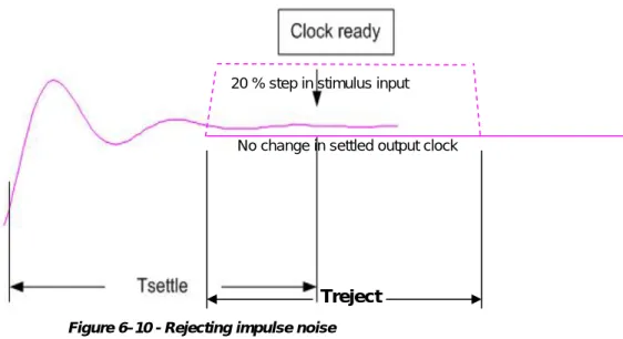
F
IGURE6–10
-
R
EJECTING IMPULSE NOISE...45
F
IGURE6–11
-
D
EVICES
TATES ANDS
TATET
RANSITIONS FORB
ASICF
LOWP
ROVISIONING...48
F
IGURE6–12
-
ETEA
P
OWER-
ONI
NITIALIZATIONF
LOW...49
F
IGURE6–13
-
C
ONCEPTUALL
AYERING...72
F
IGURE6–14
-
PW
E
XAMPLES...73
F
IGUREV–1
-
N
ETWORKC
LOCKING-
CMTS
TOCM...167
F
IGUREV–2
-
P
RIMED
IFFERENTIALC
LOCKR
ECOVERY...168
F
IGUREV–3
-
A
DAPTIVEC
LOCKR
ECOVERY...169
List of Tables
T
ABLE6-1
-
G.823
ANDG.824
C
LOCK REQUIREMENTS...24
T
ABLE6-2
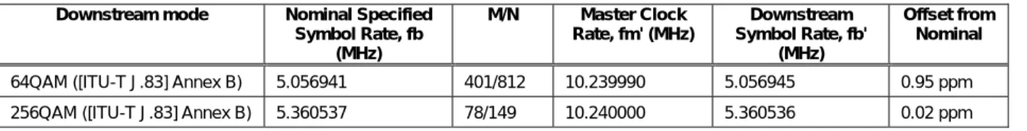
-
DOCSIS
S
YMBOLC
LOCKS...35
T
ABLE6-3
-
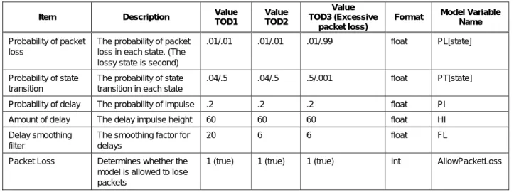
N
ETWORKI
MPAIRMENTC
ONSTANTS(NIM1) ...42
T
ABLE6-4
-
N
ETWORKI
MPAIRMENTC
ONSTANTS(NIM2) ...42
T
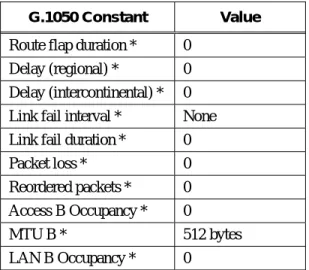
ABLE6-5
–
NIM2
C
HARACTERISTICS...43
T
ABLE6-6
-
C
LOCKR
ECOVERYP
ERFORMANCEC
ONSTANTS...45
T
ABLE6–7
-
ETEA
I
NITIALIZATIONF
LOW...49
T
ABLE6–8
-
DHCP
O
PTION43
S
YNTAX...52
T
ABLE6–9
-
TLV
D
EFINITIONS...53
T
ABLE6–10
-
TLV
TOMIB
O
BJECTM
APPING...74
T
ABLEA–1
-
DOCSIS
E
VENTSE
XTENSIONS...77
T
ABLEIII–1
-
U
PSTREAMB
ANDWIDTH COMPUTED FROMDOCSIS
2.0 ...158
T
ABLEIII–2
-
A
NE
XAMPLE OFU
PSTREAMB
ANDWIDTHU
SAGE...159
T
ABLEIII–3
-
A
NE
XAMPLE OFD
OWNSTREAMB
ANDWIDTHU
SAGE...159
T
ABLEIV–1
-
S
TRUCTUREA
GNOSTICT1
PW
C
ONFIGURATIONF
ILEE
XAMPLE...160
T
ABLEIV–2
-
S
TRUCTUREA
GNOSTICE1
PW
C
ONFIGURATIONF
ILEE
XAMPLE...161
T
ABLEIV–3
-
S
TRUCTUREA
WARE NXDS0
PW
C
ONFIGURATIONF
ILEE
XAMPLE...162
T
ABLEIV–4
-
S
TRUCTUREA
WARE NXDS0
PW
C
ONFIGURATIONF
ILEE
XAMPLE...163
T
ABLEIV–5
-
S
TRUCTUREA
WARE NXDS0
PW
C
ONFIGURATIONF
ILEE
XAMPLE...164
1 SCOPE AND PURPOSE
1.1 Introduction and Overview
Business Services over DOCSIS-TDM Emulation service (BSoD-TE) is a method for cable operators to deliver T1,
E1 and NxDS0 emulation services that meet or exceed the quality requirement of applications that use such
services. This specification is part of the DOCSIS
®family of specifications developed by Cable Television
Laboratories (CableLabs), and in particular, defines the BSoD-TE architecture and components that comply with
DOCSIS. This specification was developed by CableLabs for the benefit of the cable industry, and includes
contributions by operators and vendors from North America, Europe, and other regions.
In legacy telecommunication networks, telephone calls are often brought into households, one at a time, over
twisted pair wires. To transport many telephone calls at once (i.e., between business, wireless base stations and in
the telephone network), single calls are time-multiplexed together into 'T1' signals. A single T1 signal carries 24
individual calls, and a similar European 'E1' signal carries 32 calls. Since T1 and E1 (T1/E1) services have been
deployed for quite some time, the performance standards, tariffs and market are well defined. A number of ITU and
ANSI standards define the various aspects of T1/E1 services. Moreover, the usage and deployment models of T1/E1
lines are well understood.
This specification outlines the methods by which T1/E1 structured, unstructured, and fractional signals can be
converted to IP packets, transported over a DOCSIS IP network, and converted back to T1/E1 signals with high
reliability and quality. Figure 1–1 shows a simple T1 Service delivered between two customer sites over DOCSIS.
T1/E1 contained in Pseudo
Wire IP Over DOCSIS
TE-CMTS
TE-CM
TE-CM
RFI Interface
T1/E1
T1/E1
A TE-CM contains a CM integrated with a TDM/IP-T1/E1 converter
Figure 1–1 - Example of T1 Service Delivery1.2 Assumptions
In developing this specification, the following assumptions were made concerning the implementation and
deployment of BSOD-TE systems:
•
Interoperation with DOCSIS CMTS versions and options:
Existing CMTSs can lock their existing DOCSIS symbol clock or DOCSIS SYNC message generation to
master clock inputs for both ATDMA and S-CDMA. The chain of clock synchronization is that Stratum 1
Traceable Reference drives the DOCSIS master clock; the master clock drives the DOCSIS downstream timing;
and the CM recovers timing from the DOCSIS downstream).
Some CM silicon originally developed for DOCSIS 1.1 or 2.0 residential data modems can be used in a design
where the symbol clock or DOCSIS SYNC message may be recovered to generate a T1/E1 clock.
•
From time to time this document may refer to the voice communications capabilities of a TE-CM device /
TDM-IP protocol in terms of "IP Telephony." The legal/regulatory classification of IP-based voice
communications provided over cable networks and otherwise, and the legal/regulatory obligations, if any, borne
by providers of such voice communications, are not yet fully defined by appropriate legal and regulatory
authorities. Nothing in this specification is addressed to, or intended to affect, those issues. In particular, while
this document uses standard terms such as "call," "call signaling," "telephony," etc., it should be recalled that,
while a TE-CM device / TDM-IP protocol performs activities analogous to these PSTN functions, the manner
by which it does so differs considerably from the manner in which they are performed in the PSTN by
telecommunications carriers, and that these differences may be significant for legal/regulatory purposes.
Moreover, while reference is made here to "IP Telephony," it should be recognized that this term embraces a
number of different technologies and network architectures, each with different potential associated
legal/regulatory obligations. No particular legal/regulatory consequences are assumed or implied by the use of
this term.
•
TE-CMs are always connected to a TE-CMTS with QoS support for constant bit rate flows. The TE-CMTS
complies with DOCSIS 1.1 or 2.0. A DOCSIS 1.0 CMTS will not be able to host TE-CMs. DOCSIS 1.1 may
be limited in upstream bandwidth; TE-CM data flows are symmetric upstream and downstream.
•
J1 can be partially supported, as outline in Section 6.3.1.
•
It's not in the scope of this specification to cover interoperation between dissimilar services, i.e., between E1
and T1.
•
The following requirements are market specific and are out of scope in this specification:
•
Path redundancy and equipment redundancy (like redundant power supplies),
•
Environmental hardening, such as clock stability over temperature.
•
There is not sufficient need to support the 'octet-aligned format' of [ID SAToP] Section 5.2, which is designed
to simplify the data handling in and out of a Sonet/SDH virtual tributary/container. This specification does not
support that format.
1.3 Requirements and Conventions
Throughout this document, the words that are used to define the significance of particular requirements are
capitalized. These words are:
"MUST"
This word means that the item is an absolute requirement of this specification.
"MUST NOT"
This phrase means that the item is an absolute prohibition of this specification.
"SHOULD"
This word means that there may exist valid reasons in particular circumstances to ignore
this item, but the full implications should be understood and the case carefully weighed
before choosing a different course.
"SHOULD NOT"
This phrase means that there may exist valid reasons in particular circumstances when the
listed behavior is acceptable or even useful, but the full implications should be understood
and the case carefully weighed before implementing any behavior described with this
label.
"MAY"
This word means that this item is truly optional. One vendor may choose to include the
item because a particular marketplace requires it or because it enhances the product, i.e.,
another vendor may omit the same item.
2 REFERENCES
2.1 Normative References
In order to claim compliance with this specification, it is necessary to conform to the following standards and other
works as indicated, in addition to the other requirements of this specification. Notwithstanding, intellectual property
rights may be required to use or implement such normative references.
[DEPI]
Downstream External PHY Interface, CM-SP-DEPI-I05-070223, February 23, 2007, Cable
Television Laboratories, Inc.
[DRFI]
Downstream RF Interface Specification, CM-SP-DRFI-I05-070223, February 23, 2007, Cable
Television Laboratories, Inc.
[DOCSIS CMCI]
Data-Over-Cable Service Interface Specifications, Cable Modem to Customer Premise
Equipment Interface Specification, SP-CMCI-I10-050408, April 8, 2005, Cable Television
Laboratories, Inc.
[DOCSIS DTI]
Data-Over-Cable Service Interface Specifications, DOCSIS Timing Interface,
CM-SP-DTI-I04-061222, December 22, 2006, Cable Television Laboratories, Inc.
[DOCSIS
MULPIv3.0]
Data-Over-Cable Service Interface Specifications, DOCSIS 3.0, MAC and Upper Layer
Protocols Interface Specification, CM-SP-MULPIv3.0-I05-070803, August 3, 2007, Cable
Television Laboratories, Inc.
[DOCSIS
OSSIv2.0]
Data-Over-Cable Service Interface Specifications, DOCSIS Operations Support System
Interface Specification, CM-SP-OSSIv2.0-I10-070803, August 3, 1007, Cable Television
Laboratories, Inc.
[DOCSIS
OSSIv3.0]
Data-Over-Cable Service Interface Specifications, DOCSIS 3.0, Operations Support System
Interface Specification, CM-SP-OSSIv3.0-I04-070803, August 3, 2007, Cable Television
Laboratories, Inc.
[DOCSIS 3.0
PHY]
Data-Over-Cable Service Interface Specifications, DOCSIS 3.0 Physical Layer Specification,
CM-SP-PHYv3.0-I05-070803, August 3, 2007, Cable Television Laboratories, Inc.
[DOCSIS RFI
1.1]
ANSI/SCTE 23-1 2005, DOCSIS 1.1 Part 1: Radio Frequency Interface, SCTE.
[DOCSIS RFI
2.0]
DOCSIS 2.0 Radio Frequency Interface Specification, CM-SP-RFIv2.0-I11-060602, June 2,
2006, Cable Television Laboratories, Inc.
[DS0 MIB]
IETF RFC 2494, D. Fowler, "Definitions of Managed Objects for the DS0 and DS0 Bundle
Interface Type", January, 1999, Internet Engineering Task Force.
[DS1 MIB]
IETF RFC 2495, D. Fowler, "Definitions of Managed Objects for the DS1, E1, DS2 and E2
Interface Types", January, 1999, Internet Engineering Task Force.
[eDOCSIS]
Data-Over-Cable Service Interface Specifications, eDOCSIS Specification,
CM-SP-eDOCSIS-I13-070803, August 3, 2007, Cable Television Laboratories, Inc.
[IANA UDP
PORTS]
Internet Assigned Numbers Authority, Port Numbers, April 2006,
http://www.iana.org/assignments/port-numbers.
[IANA RTP
TYPES]
Internet Assigned Numbers Authority, RTP Parameters, February 2006,
[IEEE 1588]
"IEC/IEEE Standard for a Precision Clock Synchronization Protocol for Networked
Measurement and Control Systems", 61588-2004, November 15, 2004, IEEE.
[IF MIB]
IETF RFC 2670, M. St. Johns, " Radio Frequency (RF) Interface Management Information
Base for MCNS/DOCSIS compliant RF interfaces", August 1999, Internet Engineering Task
Force.
[ISO 8025]
ISO 8025 (December 1987) – Information processing systems - Open Systems
Interconnection - Specification of the Basic Encoding Rules for Abstract Syntax Notation One
(ASN.1).
[ITU-T G.703]
ITU-T Recommendation G.703 (11/01) - "Physical/electrical characteristics of hierarchical
digital interfaces", International Telecommunication Union.
[ITU-T G.704]
ITU-T Recommendation G.704 (10/98) - "Synchronous Frame Structures Used At 1544,
6312, 2048, 8488 and 44 736 Kbit/s Hierarchical Levels", International Telecommunication
Union.
[ITU-T G.706]
ITU-T Recommendation G.706 (4/91) - "Frame alignment and cyclic redundancy check
(CRC) procedures relating to basic frame structures defined in Recommendation G.704",
International Telecommunication Union.
[ITU-T G.732]
ITU-T Recommendation G.732 (11/88) - "Characteristics of primary PCM multiplex
equipment operating at 2048 kbit/s", International Telecommunication Union.
[ITU-T G.810]
ITU-T Recommendation G.810 (8/96) - "Definitions And Terminology For Synchronization
Networks", International Telecommunication Union.
[ITU-T G.823]
ITU-T Recommendation G.823 (03/00) - "The control of jitter and wander within digital
networks which are based on the 2048 kbit/s hierarchy", International Telecommunication
Union.
[ITU-T G.824]
ITU-T Recommendation G.824 (03/00) - "The control of jitter and wander within digital
networks which are based on the 1544 kbit/s hierarchy", International Telecommunication
Union.
[ITU-T G.1020]
ITU-T Recommendation G.1020 (11/03) – "Performance parameter definitions for quality of
speech and other voiceband applications utilizing IP networks.", International
Telecommunication Union.
[ITU-T G.1050]
ITU-T Recommendation G.1050 (11/05) – "Network model for evaluating multimedia
transmission performance over internet protocol", International Telecommunication Union.
[ITU-T J.83]
ITU-T Recommendation J.83 (04/97) - "Digital multi-program systems for television, sound
and data services for cable distribution", International Telecommunication Union.
[MEF8]
Metro Ethernet Forum, Technical Specification MEF8, "Implementation Agreement for the
Emulation of PDH Circuits over Metro Ethernet Networks", October 2004.
[ID PW MIB]
T. Nadeau, D. Zelig, "Pseudo Wire (PW) Management Information Base,"
draft-ietf-pwe3-pw-mib-06.txt, July 2005, Internet Engineering Task Force.
[ID PWTC]
T. Nadeau, D. Zelig, "Definitions for Textual Conventions and OBJECT-IDENTITIES for
Pseudo-Wires Management", draft-ietf-pwe3-pw-tc-mib-06.txt, July 2005, Internet
Engineering Task Force.
[ID VCCV]
T. Nadeau, R. Aggarwal, "Pseudo Wire Virtual Circuit Connectivity Verification (VCCV)",
draft-ietf-pwe3-vccv-07.txt, August 2005, Internet Engineering Task Force.
[RFC 1123]
IETF RFC 1123/STD0003, Braden, R., "Requirements for Internet Hosts – Application and
Support", October 1989, Internet Engineering Task Force.
[RFC 1157]
IETF RFC1157/STD0015, J.D. Case, M. Fedor, M.L. Schoffstall, J. Davin, Simple Network
Management Protocol (SNMP), May 1990. Internet Engineering Task Force.
[RFC 1350]
IETF RFC 1350, K. Sollins, "The TFTP Protocol (Revision 2) ", July 1992, Internet
Engineering Task Force.
[RFC 2131]
IETF RFC 2131, R. Droms "Dynamic Host Configuration Protocol ", March 1997, Internet
Engineering Task Force.
[RFC 2132]
IETF RFC 2132, S. Alexander "DHCP Options and BOOTP Vendor Extensions", March
1997, Internet Engineering Task Force.
[RFC 2494]
IETF RFC 2494, D. Fowler, "Definitions of Managed Objects for the DS0 and DS0 Bundle
Interface Type", January 1999, Internet Engineering Task Force.
[RFC 2863]
IETF RFC 2863, K. McCloghrie, F. Kastenholz, "The Interfaces Group MIB", June 2000
Internet Engineering Task Force.
[RFC 3396]
IETF RFC 3396, T. Lemon, "Encoding Long Options in the Dynamic Host Configuration
Protocol (DHCPv4)", November 2002, Internet Engineering Task Force.
[RFC 3611]
IETF RFC 3611, T. Friedman, R. Caceres, A. Clark "RTP Control Protocol Extended Reports
(RTCP XR)", November, 2003, Internet Engineering Task Force.
[RFC 3635]
IETF RFC 3635, J. Flick, "Definitions of Managed Objects for the Ethernet-like Interface
Types", September 2003, Internet Engineering Task Force.
[RFC 3636]
IETF RFC 3636, J. Flick, "Definitions of Managed Objects for IEEE 802.3 Medium
Attachment Units (MAUs)", September 2003, Internet Engineering Task Force.
[RFC 3895]
IETF RFC 3895, O. Nicklass, "Definitions of Managed Objects for the DS1, E1, DS2, and E2
Interface Types", September 2004, Internet Engineering Task Force.
[RFC 3550]
IETF RFC 3550, H. Schulzrinne, "RTP: A Transport Protocol for Real-Time Applications",
July 2003, Internet Engineering Task Force.
[SRTP]
IETF RFC 3711, The Secure Real-time Transport Protocol (SRTP), M. Baugher, and D.
McGrew, March 2004, Internet Engineering Task Force.
[T1-403]
ANSI T1.403-1999, "Network and Customer Installation Interfaces - DS1 - Electrical
Interface", American National Standards Institute.
[TIA NIM]
TR41.4-03—05-029 (9/05) – IP Network Impairment Simulation for VoIP Performance
Testing, May 7, 2003, Telecommunications Industry Association.
[TR-62411]
AT&T Technical Reference 62411, "AT&T ACCUNET T1.5 Service Description and
Interface Specification", December 1990, AT&T.
2.2 Informative References
This specification uses the following informative references.
[DOCSIS DSG]
DOCSIS Set-top Gateway (DSG) Interface Specification, CM-SP-DSG-I10-070223, February
23, 2007, Cable Television Laboratories, Inc.
[ID CESoPSN]
Vainshtein, A. et al, "Structure-aware TDM Circuit Emulation Service over Packet Switched
Network (CESoPSN)", draft-ietf-pwe3-cesopsn-05.txt, October 2005, Internet Engineering
Task Force.
[ID ECMP]
George Swallow, G., Bryant, S., and Andersson, L., "Avoiding Equal Cost Multipath
Treatment in MPLS Networks", draft-ietf-mpls-ecmp-bcp-01.txt, July 2005, Internet
Engineering Task Force.
[ID SAToP]
Vainshtein, A. and Stein, Y., "Structure-Agnostic TDM over Packet
(SAToP)",draft-ietf-pwe3-satop-01.txt, December 2003, Internet Engineering Task Force.
[ID YTDMIP]
IETF draft, "TDM over IP", draft-ietf-pwe3-tdmoip-04.txt, Y. Stein, Sept. 21, 2005.
[MLDA]
Sisalem D. and A. Wolisz, "MLDA: A TCP-friendly Congestion Control Framework for
2.3 Reference Acquisition
•
American National Standards Institute, Intern
.
•
AT&T,
.
•
Cable Television Laboratories, Inc., 858 Coal Creek Circle, Louisville, CO 80027; Phone 1-303-661-9100; Fax
1-303-661-9199; Internet:
•
Institute of Electrical and Electronic Engineers (IEEE),
.
•
Internet Engineering Task
Note: Internet-Drafts are draft documents valid for a maximum of six months and may be updated, replaced, or
obsoleted by other documents at any time.
The list of current Internet-Drafts can be accessed at
http://www.ietf.org/ietf/1id-abstracts.txt.
Internet-Drafts may also be accessed at
•
International Telecommunication Union – Telecommunication Standardization Sector (ITU-T),
.
•
International Organization for Standardization (ISO),
.
•
Metro Ethernet Forum (MEF),
•
Society of Cable Telecommunications Engineers (SCTE),
.
•
Telecommunications Industry Associations (TIA),
3 TERMS AND DEFINITIONS
This specification defines the following terms:
Alarm
Indication
Signal
Also known as the
blue alarm
. When no incoming signal is detected, a CSU/DSU transmits an
unframed all-ones pattern to the network to maintain synchronization and announce its presence
to the network.
CU
A Clock Unit (CU) performs translations and distribution of TDM clocking information across
(and between) physical, data, and network layers.
CRU
A Clock Recovery Unit (CRU) exists in the IWF and is responsible for regenerating the circuits
clock based on the average inter-arrival time of the packets in the adaptive clocking mode, or on
the time stamp differentials received when operating in the differential clock mode. The output
clock is provided to the CU.
Channel
Service Unit
The piece of a CSU/DSU that talks to the telco network, understands framing and line coding, and
provides electrical isolation of the network from the telco network.
Data Service
Unit
The part of the CSU/DSU that interfaces with routers, switches, and packets. It has a serial port to
interface with compatible data equipment.
DS0
Digital signal 0 (DS0) is a basic digital signaling rate of 64 kbit/s, corresponding to the capacity
of one voice-frequency-equivalent channel.
E1
E1 is a physical layer telephony protocol carrying data at 2.048 Mbps. It can carry up to 32 DS0s,
each of which can carry a telephone conversation.
eTEA
An eTEA is an eDOCSIS eSAFE; an embedded version of a TEA.
Fractional
A Fractional T1 or Fractional E1 carries only a portion of the total number of DS0s that a T1 or
E1 carries.
IWF
An Interworking Function (IWF) is a logical entity. It consists of a TSP data interface on one side,
an IP Packet interface on the other side, and the functionalities to encode TDM data into a Pseudo
wire in one direction and decode TDM data from Pseudo Wire in the other direction.
J1
J1 is the Japanese version of a T1; it has some alarm and framing differences as compared with
T1.
Jitter
The fluctuation in the arrival time of a regularly scheduled event such as a clock edge or a packet
in a stream of packets. Jitter is defined in [ITU-T G.810] as fluctuations above 10 Hz. See
Wander.
LCI
A Logical CPE Interface (LCI) is a logical 802.3/Ethernet MAC frame data interface.
Loss of
Frame
Also called the
the remote end for 2.5 seconds, LOF is declared
red alarm
. When a T1 CSU/DSU is unable to synchronize framing patterns with
Loss of
signal
When no incoming pulses are received by a T1 CSU/DSU for a prescribed number of bit times,
LOS is declared. Even if only zeros were transmitted as data, some framing bits should result in
pulses on the line during that time. If LOS persists, LOF will eventually be declared because there
is no incoming signal with which to synchronize.
MTIE
Maximum Time Interval Error as defined in [ITU-T G.810].
Out of
Frame
When frame synchronization is lost, an OOF event is recorded. If OOF persists, LOF is declared.
OOF is cleared when frame synchronization is regained.
Pseudo
Wire
A Pseudo Wire (PW) is a logical entity capable of the emulation of a native service (i.e., T1) over
a Packet Switched Network (like DOCSIS IP).
Remote
alarm
indication
Also known as
yellow alarm
. When a CSU/DSU enters the red alarm state, an RAI is transmitted
in the outgoing direction. The RAI signals to the remote end that the local end is unable to
synchronize framing patterns.
T1
T1 is a physical layer telephony protocol carrying data at 1.544Mbps. It can carry up to 24 DSOs,
each of which can carry a telephone conversation. It is used mainly in North America.
TDEV
Time Deviation as defined in [ITU-T G.810].
TDM
Interface
A physical Time Domain Multiplex (TDM) telephony interface such as T1, E1, or J1. Time
Division Multiplexing (TDM) is the means by which multiple digital signals (DS0s) can be
carried on a single transmission path by interleaving portions of each signal in time.
TEA
A TDM Emulation Adapter (TEA) is a logical entity containing various functions to provide a
BSoD-TE circuit emulation service.
TE-CM
The TDM Emulation Cable Modem (TE-CM) is a special purpose cable modem that integrates a
DOCSIS eCM with an eTEA.
TE-CMTS
A TE-CMTS is a CMTS or M-CMTS that can support a TE-CM and can meet the minimum
clocking and performance goals to support BSoD-TE traffic. A TE-CMTS may or may not
support integrated TEAs.
TSP
A TDM Service Processor (TSP) consists of a TSP data interface on one side, a TDM Interface on
the other side, and the functionalities to encapsulate TSP data into TDM Interface signals in one
direction and extract TSP data from TDM Interface signals in the other direction.
4 ABBREVIATIONS AND ACRONYMS
This specification uses the following abbreviations and acronyms:
ACR
Adaptive Clock Recovery
AIS
Alarm Indication Signal
CBR
Constant Bit Rate
CM
Cable Modem
CMTS
Cable Modem Termination System
CSU
Channel Service Unit
DEPI
DOCSIS External PHY Interface
DOCSIS®
Data-Over-Cable-Service-Interface Specifications
DS
Downstream
DSU
Data Service Unit
DTI
DOCSIS Timing Interface
HFC
Hybrid Fiber Coax
IP
Internet Protocol
LOF
Loss of frame
LOS
Loss of signal
MAC
Media Access Control
OOF
Out of frame
PDCR
Precise Differential Clock Recovery
PW
Pseudo Wire
RAI
Remote alarm indication
RF
Radio Frequency
UDP
User Datagram Protocol
5 TECHNICAL OVERVIEW
5.1 Background
Throughout the evolution of communication networks the T1 and E1 service that is delivered to the customer has
remained relatively consistent (in large part due to the strict ITU and ANSI standards), however the method of
delivering the T1 or E1 service has changed to increase efficiencies and leverage new technologies. Both SONET
and ATM historically have been adapted to transport T1 and E1 services; now MPLS and IP networks are also
being used. Various standards bodies and vendors have created methods for circuit emulation of T1 and E1 services
across IP networks, leveraging the successful ATM circuit emulation technology developed in the 90s. This
CableLabs specification leverages the work done in the ITU and IETF to define circuit emulation of T1 and E1 over
a DOCSIS network.
This specification describes the architecture and components of a network that delivers emulated T1 or E1 or
NxDS0 services over DOCSIS. It defines the T1, E1, or NxDS0 service delivered to the end customer, the
requirements of a BSoD-TE compliant cable modem (TE-CM), the requirements of a BSoD-TE compliant CMTS
(TE-CMTS), the requirements of the TDM Emulation Adaptor (TEA), and Pseudo Wires (PW) that cross the packet
network connecting two TEAs.
5.2 Principal technical considerations
This section describes the principle technologies and operational considerations germane to the development of a
T1/E1-bearing TE-CM and its use. Major sub-topics include:
•
Clocking – T1/E1 transport technology is synchronous in nature; requiring accurate and stable clocking. Since
T1 transport requires that T1 signals are handed from one service provider to another, each service provider
must adhere to the same clocking requirements. Further, these synchronous clocking requirements must be very
stringent to ensure reliable operation. The section on clocking (Section 5.5) will further describe these
requirements largely based on existing ITU and ATIS requirements.
•
Data Protocol
1. Voice protocol - Phone calls at termination are completely analog, carrying linear voice signals over
dedicated wires. It wasn't long before the phone companies realized that a wire could carry more than one
phone call if the calls were time-multiplexed on the wire. Calls are now time-sampled, and the resulting digital
signals are time-multiplexed over wires in T1/E1 formats (among others).
2. Data protocol - It did not take long for engineers to realize that T1/E1 transport could be used for standard
data (not just voice). T1 signals are now used to transport digital data in many different data formats which are
beyond the scope of this spec. This specification accommodates the transport of either voice or data by
specifying more than one data format for the IP packets that carry the T1 information over DOCSIS channels.
The sections below addressing 'structure agnostic' protocol are germane to data transport. Most of this
specification addresses T1 transport of voice calls, but the specification accommodates data transport as well.
3. Signaling data protocol – To successfully combine several voice phone calls into a T1 structure, data
describing the state of each call must be included. Such call state data may include the progress of the call and
the health of the transport network carrying the call. Several existing standards describe this signaling data.
This specification describes the format for signaling data in the IP packets that carry the T1 information over
DOCSIS channels.
•
Operations – The synchronous transport systems put together by telecommunications carriers for T1 data have
been refined over the years to become very reliable. But the manner by which a DOCSIS transport system
performs this service differs considerably from the manner in which they are performed in the PSTN by
telecommunications carriers. Operators of DOCSIS systems can alter their standard operating procedures to
accommodate these differences. This specification makes many suggestions for operators who must configure
DOCSIS systems to carry emulated T1/E1 data as specified herein.
5.3 Devices/Interfaces
5.3.1
TE-CM
A TE-CM is a standard DOCSIS cable modem that contains an embedded TDM Emulation Adaptor (eTEA) giving
it the ability to offer T1/E1 services. A TE-CM may have architecture and interfaces similar to that shown in
Figure 5–1 below. The power supply and other functionality that is out of scope are not shown. The
elements/interfaces are described as follows:
•
DOCSIS eCM – This is a standard DOCSIS CM conforming to DOCSIS 1.1, 2.0, 3.0 or greater. It must be able
to carry a constant bit rate service flow carrying packets at bit rates sufficient to handle T1/E1 data,
management and signaling as defined herein. It also contains [eDOCSIS] functions sufficient to support eTEA
and Ethernet functionality. Per DOCSIS, it has both RF and Ethernet interfaces. The embedded DOCSIS CM
chipset provides clocking to the eTEA recovered from the DOCSIS symbol clock or DOCSIS SYNC message
as defined in Section 6.4.
•
eTEA – The TE-CM contains an eTEA that operates as an eDOCSIS eSAFE.
•
T1/E1 Interface – This interface is a standard T1/E1 connector.
•
Ethernet Interface – This interface is a standard Ethernet connector (RJ45). It may, in future, provide the
capability to exchange IP packets with eTEA or other BSoD-TE entities that may exist outside the TE-CM.
•
Logical CPE Interface – This is an unspecified interface between the eTEA and eCM.
eCM LCI eTEA
RFI TE-CM nxT1/E1 DOCSIS Symbol/ Sync Clock* Ethernet Figure 5–1 - TE-CM
5.3.2
TE-CMTS
A TE-CMTS is a standard DOCSIS CMTS that contains the necessary clocking functionality necessary to support a
TE-CM and may also include a TDM Emulation Adaptor (TEA) giving it the ability to terminate T1/E1 services. A
TE-CMTS may have architecture and interfaces similar to that shown in Figure 5–2 below. The power supply and
other functionality that is out of scope are not shown. The elements/interfaces are described as follows:
•
RF – This is the standard DOCSIS CMTS signal as transceived on the HFC network.
•
DOCSIS CMTS – This is a standard DOCSIS CMTS conforming to DOCSIS 1.1, 2.0, 3.0 or greater. It must be
able to carry a constant bit rate service flow carrying packets at bit rates sufficient to handle the IP Pseudo Wire
traffic and management as defined herein. Per DOCSIS, it has both RF and IP interfaces. The CMTS may be an
M-CMTS in which case the M-CMTS specification defines compliant IP, RF, and synchronization interfaces.
•
Clocking Unit – When the TEA is not integrated within the TE-CMTS, at a minimum the Clocking Unit
functionality must be implemented as part of the TE-CMTS. A TE-CMTS has either a [DOCSIS DTI] or a
BITS external synchronization interface as defined in Section 6.4. This is used to time and/or clock the
DOCSIS symbol clock or DOCSIS SYNC message for a TE-CM to recover.
•
TEA – A TE-CMTS may contain a TEA and TDM interface(s).
•
Ethernet Interface – The Ethernet interface will carry IP traffic to and from the managed IP network.
Figure 5–2 - TE-CMTS
L2E is an unspecified Layer 2 Ethernet Interface.
5.3.3
Embedded TDM Emulation Adaptor (eTEA)
An Embedded TDM Emulation Adaptor (eTEA) is an eSAFE device as specified by [eDOCSIS]. An eTEA is
embedded in a TE-CM.
An eTEA has a T1, E1, or J1 interface connector and contains the following elements/interfaces:
•
Pseudo Wires (PW1, PW2, …, PWN) – Pseudo Wires are logical IP packet flows that contain encapsulated
TDM traffic. Pseudo Wires are terminated and generated by IWF.
•
Interworking Function (IWF) – The Interworking function consists of a TSP data interface on one side, an IP
Packet interface on the other side, and the functionalities to encapsulate TDM data into a Pseudo wire in one
direction and extract TDM data from Pseudo Wire in the other direction. Encapsulation and transmission may
involve clocking from the CU.
•
TDM Service Flows (TS1, TS2, …, TSN) – TDM data associated with a Pseudo Wire and TDM interface. The
TDM Service Flows may be multiplexed onto one or more TDM interfaces through the TDM Service
Processor.
•
TDM Service Processor – The TDM Service Processor connects and may multiple TDM Service Flows onto
one or more TDM interfaces.
•
Ethernet Interface. This Customer facing Ethernet interface has the following uses:
•
To launch the optional 1588 local master timing function on the customer Ethernet network per Section
6.4.5;
•
For DOCSIS testing of an eCM;
•
For testing of clock recovery per Section 6.4.7.1;
•
For (out of scope) use to carry TDM data per Section 5.3.1.
•
TDM Interface – The TDM interface is one or more T1, E1, J1 or higher rate interface as further defined in
Section 3.
•
Clocking Unit (CU) – This element provides high quality and reliable frequency to the IWF and TDM Service
Processor. The CU receives clocking from the eDOCSIS module. The eDOCSIS module through DOCSIS
requirements must lock to the DOCSIS symbol clock and DOCSIS SYNC message. The eDOCSIS module
must provide one of these recovered clocking signals to the CU. Since a TE-CMTS is synchronized to a
Stratum 1 traceable reference, the recovered clock from DOCSIS not only has the stability needed for DOCSIS
operation, it also has stability needed for T1/E1 synchronization. Section 6.4 describes several clocking modes
that may include the CU interfacing with the TDM Service Processor and IWF.
Figure 5–3 - eTEA
5.3.4
TDM Emulation Adaptor (TEA)
A TDM Emulation Adaptor (TEA) may be implemented in a TE-CMTS or other device unspecified in the network.
A TEA has a T1, E1, or J1TDM Interface connector and contains the following elements/interfaces:
•
L2 Ethernet – This is the Layer 2 Ethernet element where IP Pseudo Wires are transceived.
•
Pseudo Wires (PW1, PW2, …, PWN) – Pseudo Wires are logical IP packet flows that contain encapsulated
TDM traffic. Pseudo Wires are terminated and generated by IWF.
•
Interworking Function (IWF) – The Interworking function consists of a TSP data interface on one side, an IP
Packet interface on the other side, and the functionalities to encapsulate TDM data into a Pseudo wire in one
direction and extract TDM data from Pseudo Wire in the other direction. Encapsulation and transmission may
involve clocking from the CU.
•
TDM Streams (TS1, TS2, …, TSN) – TDM data associated with a Pseudo Wire and TDM interface. The TDM
Streams may be multiplexed onto one or more TDM interfaces through the TDM Service Processor.
•
TDM Service Processor – The TDM Service Processor connects and may multiplex TDM Streams onto one or
more TDM interfaces.
•
TDM Interface – The TDM interface is one or more T1, E1, J1 (or higher rate) TDM interface.
•
Clocking Unit (CU) – This element provides high quality and reliable frequency to the IWF and TDM Service
Processor. The CU receives clocking from a Stratum 1 traceable reference through either a DTI or BITS
interface, and a recovered clock from the clock recovery unit within the IWF. Section 6.4 describes several
clocking modes that may include the CU interfacing with the TDM Service Processor and IWF.
L2 Ethernet IWF nxT1/E1 L2E
TEA
TDM Service ProcessorCU Stratum 1 Traceable Clock Recovered Clock Differential Ref Clk PW1 PW2 PWn TSx1 TSx2 TSxn RX Clock TX Clock Ethernet L2E Ethernet 1588 Figure 5–4 - TEA
5.4 Architecture
A BSoD-TE service can be deployed in several architectures. In any architecture the BSoD-TE service has two end
points that each contain a TEA or eTEA (TEA peers). Each device presents a TDM interface to the customer or
network and a Pseudo Wire connecting the TEA peers logically across the IP network.
Three general architectures exist based on the existing market for T1 and E1 services. In all three architectures one
end of the BSoD-TE service originates in a TE-CM containing an eTEA. The three architectures differ based on
where the other end of the service is terminated and thus where the other TEA/eTEA exists.
There are a variety of existing T1/E1 services including wireless backhaul, private line, PBX extension, PBX PSTN
access, etc. Comprehensive T1/E1 service may include a combination of these three architectures and may include
partnering with other operators for part of the implementation.
5.4.1
TE-CM to TE-CMTS w/TEA
In this architecture the BSoD-TE service originates in a CM (containing an eTEA) and terminates at the
TE-CMTS which contains a TEA. Figure 5–5 shows this architecture with the Pseudo Wire flow shown as the dotted
line. This is not the termination of the T1 or E1 circuit, just the two ends of the BSoD-TE circuit emulation. The T1
or E1 service will continue from the CMTS into the traditional TDM network.
This architecture places delay and QoS requirements on the DOCSIS network, but minimizes the impairments that
the IP network may place on the BSoD-TE service. This architecture however requires TDM transport facilities at
the hub/headend locations where the CMTS is located which may not be feasible or cost effective for some
operators that prefer or require the BSoD-TE service to have a more centralized termination.
Figure 5–5 - T1 to Hub Architecture
5.4.2
TE-CM to Centralized TEA
In this architecture the BSoD-TE service originates in a TE-CM and terminates in a centralized router or other
unspecified device that contains a TEA. The TEA may exist in a router, gateway, switch or other device which is
out-of-scope for this specification with the exception of the TEA functionality. Figure 5–6 shows this architecture
with the Pseudo Wire flow shown as the dotted line. This is not the termination of the T1 or E1 circuit, just the two
ends of the BSoD-TE circuit emulation. The T1 or E1 service will continue from the CMTS to its termination within
traditional TDM network.
This architecture places delay, synchronization and QoS requirements on the TE-CMTS, which in this case does not
contain a TEA. This architecture places delay and QoS requirements on the DOCSIS and core managed IP network.
While this architecture requires a slightly more complex provisioning of the network, it centralizes the termination
of the BSoD-TE circuit emulation in the core. This means there are fewer BSoD-TE devices to manage and that the
TE-CMTS does not have an integrated TEA. This simplifies the TE-CMTS and reduces or eliminates modifications
to existing installed CMTSs. This architecture eliminates the need for TDM transport facilities at each hub/headend
since the Pseudo Wires will pass through the TE-CMTS (as IP packets) and be routed over the existing IP transport
to the core.
DOCSIS HFC TE-CM T1/E1 TE-CMTS TEA DSx TDM eTEA End User EquipmentFigure 5–6 - T1 to TDM core, IXC or PSTN
5.4.3
TE-CM to TE-CM through TE-CMTSs and Core
In this architecture the BSoD-TE service originates in a TE-CM (containing an eTEA) and in a second TE-CM
(containing an eTEA). Figure 5–7 shows this architecture with the Pseudo Wire flow shown as the dotted line. In
this architecture the T1 service is end-to-end with transport of the circuit through the managed IP core network. If
the T1 circuit requested by the customer is accessible by a single hub/headend a single TE-CMTS may be utilized
with the Pseudo Wire being routed locally.
This architecture places delay, synchronization and QoS requirements on the TE-CMTS, which in this case does not
have a TEA. This architecture places delay and QoS requirements on the DOCSIS and core managed IP network.
While this architecture requires a more complex provisioning of the network, it can be deployed with minimal
upgrades to the existing installed CMTSs and does not require any modifications to the core equipment. This
architecture eliminates the need for TDM transport facilities at each hub/headend since the Pseudo Wires will pass
through the TE-CMTSs and existing IP transport in the core between the two TE-CMs. There are however service
limitations imposed by this architecture. This architecture only enables a provider to offer private line T1/E1
services between two customer sites. This architecture does not enable T1/E1 services to the PSTN or any other
TDM network.
Figure 5–7 - T1 private line between two customer sites End User Equipment
T1/E1
GigE DOCSIS
HFC
End User Equipment
T1/E1 DOCSIS HFC GigE Managed IP Core Network
TE-CMTS TE-CMTS TE-CM eTEA TE-CM eTEA
End User Equipment
TE-CM T1/E1 TE-CMTS GigE (IP) DOCSIS HFC DSx Router or other equipment TEA TD eTEA Managed IP Core
5.4.4
Other Architecture Considerations
For many operators, a complete T1/E1 service offering will require a mixture of these three architectures. In most
cases this will be a mixture from Sections 5.4.3 and either 5.4.1 or 5.4.2. Figure 5–8 depicts a potential hybrid
architecture.
An MSO may also choose to partner with other MSOs creating exchange agreements where a Pseudo Wire may
flow over both of there managed IP networks and terminate in a TE-CM in each of their networks. Moreover, a
MSO may choose to partner with another operator to offer T1/E1 services outside their network nationally or
internationally. In most cases this will require the MSO to terminate and aggregate the BSoD-TE circuit emulation
for handoff as a high rate TDM interface, like a DS3. This would also be the case if an MSO chooses to offer
wireless backhaul services. The MSO would need to aggregate multiple Pseudo Wire IP flows from several
TE-CMs, terminate the BSoD-TE circuit emulation and handoff to the wireless operator in a high speed aggregate TDM
DS3 type interface. Lastly, an operator could choose the TEA defined in this specification to transport TDM traffic
across the managed IP core network between two routers or other devices. The details of this are out-of-scope for
this specification; however, it is possible with this technology.
Figure 5–8 - Comprehensive private and public T1/E1 services
5.4.5
M-CMTS & CMTS Architecture Considerations
The Modular-CMTS (M-CMTS) architecture offers many advantages when considering a BSoD-TE service. Since a
T1 or E1 service has constant symmetric bandwidth of 1.5M.bits to 2M.bits, a traditional CMTS architecture may
not scale as well as an M-CMTS. The M-CMTS architecture decouples the upstream and downstream into separate
devices that can be scaled independently. Since BSoD-TE, residential broadband data service, VoIP and other
services all utilize the DOCSIS network this independent scalability offers greater economics and flexibility as
various services are deployed.
In addition to the scalability, Modular-CMTS requires the DOCSIS Timing Interface ([DOCSIS DTI]). This is used
for Modular-CMTS operation, but can also be used to support BSoD-TE synchronization requirements as described
in Section 6.4.
Existing CMTS architectures may be utilized for BSoD-TE as well as the M-CMTS devices that are inherently
compliant. Existing CMTS may or may not have been designed with BSoD-TE in mind and may need some
modifications. The potential for a CMTS to be made compliant to BSoD-TE as a TE-CMTS is vendor and platform
dependent. The CMTS will need to have a synchronization interface and support QoS requirements in order to
support advanced clocking modes beyond adaptive clock recovery. This may not require any modifications for some
vendors, for others rather minor changes and for some it may not be possible on existing platforms. Moreover, some
vendors may be able to offer upgrades to existing CMTS platforms to not only include TE-CMTS functionality, but
also an integrated TEA.
Router or other equipment
TEA
DSx
TDM End User Equipment
T1/E1
GigE DOCSIS
HFC
End User Equipment T1/E1 DOCSIS HFC GigE Managed IP Core Network TE-CMTS TE-CMTS TE-CM eTEA TE-CM eTEA End User Equipment
T1/E1 DOCSIS HFC TE-CMTS TE-CM eTEA