PLEASE READ ALL DIRECTIONS BEFORE STARTING INSTALLATION
I n s t a l l a t i o n I n s t ru c t i o n s
401 S. Grand Ave. Santa Ana, CA 92705 (800) 211-2767 www.twobros.com
DOWNLOAD THE TOPTUNE SOFTWARE
AND LATEST MAPS FROM OUR
WEBSITE:
www.twobros.com
THE IGNITION MUST BE TURNED
OFF BEFORE INSTALLATION!
PARTS LIST
1
Juice Box Pro™
1
USB Cable
1
Top Tune CD-ROM
1
Installation Guide
2
Velcro strip
1
Alcohol swab
1
O2 Optimizer
S electing the M ap Position
The J uice B ox Pro comes loaded with up to ten maps. U sing a #1 Phillips
screwdriver, turn the map select dial to toggle between the loaded maps. Refer to the map position table below for the maps included in your J uice B ox Pro.
U sing the R PM R ange Dials
The Low, M id, and High R PM Dials refer to the R PM range, in thirds, of your vehicle. Each dial allows +/- 10% fuel adjustment on top of what fuel changes are done in the map. W ith the dial facing straight up, there is no additional fuel change. For example, if your vehicle revs to 15,000 R PM :
• the low R PM dial will adjust 0-5000 R PM • the mid R PM dial will adjust 5001-10000 R PM • the high R PM dial will adjust 10001-15000 R PM
U sing Top Tune
Take your tuning to the next level with the Top Tune software.
1 Insert the CD provided into your computer’s cd-rom drive. The launch program will run automatically.
If auto-run is disabled, double-click the M y Computer icon then double-click the CD drive icon. Double-click TB R Top Tune.exe to manually start the CD.
2 Click Install S oftware and follow the on-screen instructions to install the Top Tune software. The Top Tune software and maps will be stored in C:\Program Files\TB R Top Tune.
3 Click M ap Database. All maps will automatically be installed to the C:\Program Files\TB R Top Tune\maps folder.
1 Connect the U S B cable from the computer to the J uice B ox Pro. Verify the cable is fully seated in the J uice B ox Pro.
2 Run the Top Tune software by double-clicking the program icon installed on your desktop or on your start menu.
3 Click Open M ap File and select a map file.
4 Click S end M ap. You can send the map to any of the ten map positions.
The values in the map represent a percentage of fuel change over stock. A value of 10 in the map indicates at that throttle position and R PM range the vehicle will be Installing the Top Tune S oftw are
Loading Additional M aps
Altering M aps U sing Top Tune U S B Port High R PM Dial M id R PM Dial Low R PM Dial M ap S elect S tatus Light (Power to U nit) Position 0 Zero map
Position 1 Stock exhaust
Stock air filter 2012 Honda CBR1000RR Position 2 Two Brothers VALE slip-on
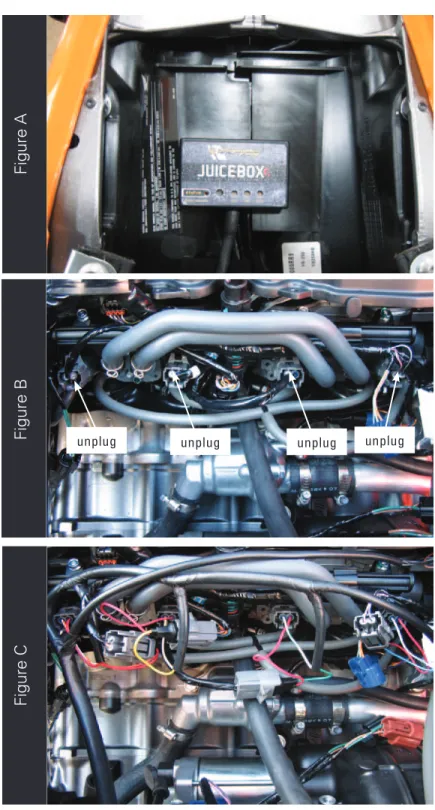
Figure A
Figure B
Figure C
6. Unplug the stock wiring harness from each injector as shown in Figure B. The lower injectors are located on the throttle bodies.
7. Attach the Juice Box Pro connectors in-line of the stock wiring harness and the injectors as shown in Figure C.
unplug unplug unplug unplug
1. Remove the main seat and the passenger seat. 2. Remove the fuel tank cover.
3. Lift the fuel tank up or remove.
4. Using the supplied velcro, secure the Juice Box Pro in the tail section. Make sure to clean both surfaces with the alcohol swab before attaching. 5. Route the Juice Box Pro harness down the left side of the bike.
9. Connect the Juicebox Pro connectors in-line of the stock TPS and wiring harness as in figure E.
Figure D
8. Locate the Throttle Position Sensor on the right side of the throttle bodies (Fig.D).
Figure D is shown with the airbox lid moved out of the way but this is not necessary
to gain access to this connector. Using a small flat blade screwdriver you can push
in on the tab to release the connector.
There are a few of these same connectors on this bike in this general area. Make
sure you are connecting tot the one bolted to the far right of the throttle body
assembly.
Unplug
Figure E
Figure F
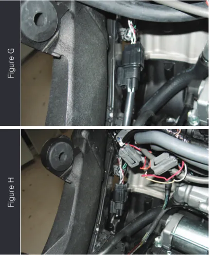
11. Locate the stock O2 sensor on the inside, left of the frame (Fig. G). Unplug the sensor.
12. Plug the Juicebox O2 Optimizer into the stock wiring harness (Fig.H).
The stock O2 sensor will no longer be connected to anything and can be removed
from the exhaust if desired.
13. Reinstall bodywork