1
Faculty of Chemistry
Technical University of Lodz
Papermaking and printing
“Estimation of impact of alternative papermaking
additives on paper web dewatering intensity and paper
properties”
Master Thesis
written in
Institute of Papermaking and Printing
under direction of
dr eng. Konrad Olejnik
2
Table of content ... 2
Preface ... 4
Summary ... 5
Objectives and scope of the thesis ... 6
1. Theoretical introduction ... 7
1.1. General information and definitions concerning papermaking process, construction of paper machine and basic functions of its elements ... 7
1.1.1. Pulp preparation ... 7
1.1.2. Stock and water systems of paper machine ... 8
1.1.2.1. Stock preparation ... 9
1.1.2.2. Stock approach flow system ... 14
1.1.2.3. Short and long circulation systems ... 14
1.1.3. Wet part of paper machine ... 15
1.1.4. Press section of paper machine ... 20
1.1.5. Dry part of paper machine... 23
1.2. Classification and characteristic of water contained in formed paper web ... 25
1.3. Intensity of paper web dewatering and energy consumption in conventional paper making process ... 33
1.4. Dewatering phenomenon ... 39
1.4.1. Mechanisms of dewatering ... 39
1.4.2.1. Kozeny-Carman equation ... 40
1.4.2.2. Hydrodynamic specific surface area assessment ... 42
1.4.3. Factors affecting drainage intensity ... 48
1.4.3.1. Stock preparation ... 49
1.4.3.2. Initial solid content and fiber alignment ... 49
1.4.3.3. Stock temperature ... 50
1.4.3.4. Permeability of pulp fiber mat ... 51
1.4.3.5. Fines content ... 52
1.4.3.6. Fiber flexibility ... 54
1.4.4.7. Retention aids ... 56
2. Research phase ... 59
2.1. Characteristic of raw materials and alternative materials used ... 59
2.2. Microscopic pictures ... 62
2.3. Pulp preparation ... 66
2.4. Methodology of analysis ... 67
2.4.1. Methods of pulp dewatering analysis ... 67
2.4.1.1. Schopper-Riegler freeness ... 69
2.4.1.2. Water retention value ... 70
2.4.1.3. Rapid-Köthen number ... 71
2.4.1.4. Hydrodynamic specific surface area ... 72
2.4.1.5. FiberXPress... 74
2.4.2. Methods of paper sheet properties analysis ... 77
3. Results and discussion ... 79
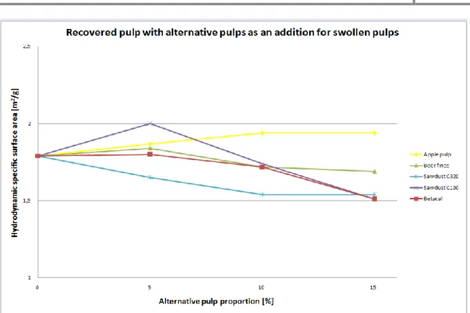
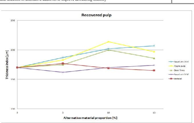
3.1. The influence of addition of alternative materials on pulp dewatering ... 79
3.1.1. Dewatering in the wire section ... 79
3.1.2. Dewatering in the press section... 84
3.2. The influence of addition of alternative materials on paper sheet properties ... 4. Conclusions ... 157
3
Annex 1 General definition and symbol list ... List of figures ... List of tables ... References ...
4
Preface
The main objective of this thesis is to assess factors affecting dewatering behavior of the paper web in the wet part of paper machine with a clear focus on the influence and the role of additives and fibers, and to search for alternative bio-based additives that can reduce the required drying energy without negatively affecting of paper quality. The aim is to elucidate the balance between dewatering and water retention value of different raw materials and additives used during paper production in relation to paper quality. This thesis contains description of researches carried out in order to find out what is the effect of the addition of bio-based additives in different ratios on pulp dewatering properties, water retention value and paper properties. Within Thesis the comparison of influence of additives was done and also comparison of different dewatering methods used was performed.
Researches were carried out using wide range of dewatering apparatus available, inter alia, at Institute of Papermaking and Printing at the Technical University of Lodz in Poland and also abroad.
Hydrodynamic specific surface area measurements were performed according to Dresden method with usage of the unique analyser, placed in Germany, at Dresden University of Technology, at Faculty of Mechanical Engineering, Professorship of Paper Technology. This cooperation was possible within European Union program called Short Term Scientific Mission during COST E54 Action with title: “Characterization of the fine structure and properties of papermaking fibres using new technologies”.
Investigations in participating paper mills were carried out with coordination of Centre of Competence Paper and Board, the Netherlands, and cooperation with experts from paper mills. Analysis was also performed in the laboratory of Smurfit Kappa Roermond Papier B.V. in Roermond with the usage of new FiberXPress device, invented and developed by Voith and Smurfit Kappa.
This thesis has been based on a part of a larger project performed in the framework of the projects: Briljant, ‘Susprise – Green biorefinery’, ‘Biorefinery program of Energy Transition’ as well as the ‘Fibre Raw Material program’ of KCPKin pulp and paper industry. Coordination of the project is performed by Centre of Competence Paper and Board, the Netherlands with the cooperation from Institute of Papermaking and Printing.
5
6
Objectives and scope of the thesis
In every area of engineering, including papermaking, there is long-standing policy to improve economy of production and quality of products. Sustainable objectives including energy and raw material savings arethe most important aims of every industry. The European paper and board industry also has set the challenging target to reduce energy consumption with yearly more than 2%. The Dutch Paper and Board industry has set their targets even further. With their energy transition initiative they have committed themselves to halve the energy consumption in the paper chain.
Drying is the most energy consuming unit operation in papermaking. The dryer section is definitely the largest consumer of thermal energy on a paper machine as steam [1]. In the Netherlands steam is obtained by the combustion of natural gas (in CHP’s), which is directly related to the oil prices. This makes steam consumption an important parameter to reduce.
The amount of drying energy required in a paper machinedepends significantlyon the dewatering efficiency of the paper web in the wet part of the paper machine. Most drainage on a paper machine occurs mechanically on the wire and press sections. When the dry solids content of a web after the paper machine press section is approximately 50% (1 g dry solids/g H2O) for example, the dryer section removes less than 1% water volume originally received
by the forming section [1]. By changing the intensity of dewatering within the wire and press section, it is possible to influence the amount of drying energy needed and save the cost of paper production accordingly. It can be seen that a 5% increase of the consistency at the start of the drying section can result in a 20% decrease in the energy requirement for drying [29]. Thereby, an increase of 1% in web dryness before the dryer section reduces the amount of water for evaporation by approximately 4% [1, 30].
The objective of the Master Thesis is to assess the possibility of influencing the dewatering efficiency in relation to paper and board quality by changing fibers or adding different alternative additives or fibers. Research work includes processing and analysis of some hydrophobic (fibrous and/or non-fibrous) bio-based additives to enhance dewatering in reference to strength properties and choosing the most optimal. Analytical work has been done to simulate the effect of usage of different furnishes under laboratory conditions and evaluate dewatering efficiency (during web drainage and pressing). Analysis provides information about correlation between additives and raw material used, and allows to compare different dewatering methods available.
7
1.
Theoretical introduction
1.1.
General information and definitions concerning papermaking
process, construction of paper machine (PM) and basic functions of
its elements
Papermaking is a multidisciplinary technology; all systems of pulp production, paper making and converting consist of a lot of operations and processes. The complexity of this process requires understanding of every unit processes.
The aim of theoretical chapter is to provide introduction to papermaking process, construction of paper machine and basic functions of its elements. Fundamentals about water contained in formed paper web, dewatering process and factors its affecting are the subject of the following chapters. Information about dewatering intensity and its relation to energy consumption are also presented.
1.1.1.
Pulp preparation
Papermaking pulp is produced using wood as a primary raw material for the paper and board industry. Wood is made from cellulose fibers that are bound together by a material called lignin [2]. At present, wood provides over 90% of the world’s virgin fiber requirement, while non-wood sources (bagasse, cereal straws, bamboo, etc.) provide remainder. Approximately one-third of all paper products is recycled as secondary fiber [3].
Wood or other fibrous feedstocks are converted into a papermaking raw material in process called pulping. The purpose of these processes is to separate the fibers from the wood and to prepare them for papermaking operations. Fibers can be separated from each other, without being too damaged, chemically or mechanically.
There are the following pulping types:
Mechanical pulping – In these processes fibers are separated from each other by applying the mechanical energy to the wood matrix. Energy causes that the bonds between the fibers break gradually and fiber bundles, single fibers and fiber fragments are released. Lignin and also the hemicelluloses are more or less softened what eases fibers separation. The composition of wood is not changed.
Chemi-mechanical pulping – In these processes only small amount of chemicals is used (and thus only a small amount of lignin is dissolved). The
8
pulp obtained from these processes – chemimechanical pulp – is also considered as belonging to the mechanical pulp family.
Chemical pulping – In these processes fibers are separated from each other when lignin and to a large extent, also the hemicellulose is dissolved and removed. Delignification is done by using chemicals. Product of chemical pulping is called pulp.
Thus, with regard to the pulping processes, the term “pulp” is collectively used for chemical, semichemical, chemimechanical, and mechanical pulps [3, 4, 5, 6].
In a pulp mill, after fibers separation, fibers are washed and screened in order to remove any remaining fiber bundles. The pulp may then be used directly to make unbleached paper, or be bleached for white paper. In an ‘integrated paper mill’ pulp may be sent directly to a paper machine section or dried and pressed into bales to be used as a raw material by paper mills worldwide [2]. Fibrous raw material which is shipped and sold (not processed into paper in the same facility) is considered as a market pulp [7].
Pulp after pulping operation is processed in different departments in order to obtain desired papermaking properties. Both chemical and mechanical pulp fibers must be mechanically treated (refined, beaten) before the fibers become suitable for papermaking. The difference is that for chemical pulp this is a separate process in the paper mill, while for mechanical pulps this happens during the mechanical pulping process itself [5].
Chemicals are added either to the stock or to the process water and for this reason it is important to define stock and water systems of the paper machine (Fig.1).
1.1.2.
Stock and water systems of the paper machine
It is possible to distinguish the following areas and systems as part of the entire paper mill water system:
Stock preparation
Stock approach flow system Short circulation
9
Fig.1. Stock and water systems in the paper machine [x].
1.1.2.1.
Stock preparation
When pulp is coming from integrated mill, stock preparation begins with repulping or the dilution of pulp from integrated mill operations at the pulp storage towers. When paper mill is not integrated with pulp mill, paper production begins with stock preparation, where baled pulp treatment runs. Stock preparation contains several unit operations as mechanical treatment of the stock before the machine chest. Stock preparation consists of:
disintegration of pulp, defibration of pulp, refining,
pulp cleaning,
proportioning, and blending of the main stock components. The main stock preparation objectives are:
To add additives: fillers, biocids, chemicals to pulp
In non-integrated mills to pump pulp from pulp mill to the paper mill To prepare properly the pulp before passing it through the headbox
Slushing operation is realized inside a special device called pulper. During slushing, water and dry pulp bales are fed into the pulper vat, and the pulper rotor creates strong
10
disintegration forces. As a result, a pumpable fiber slurry is received. This fiber slurry is then pumped to the pulper dump chest.
Objectives of slushing are the following:
to disintegrate bales into pumpable slurry by releasing fiber bonds created in the pulp dewatering and drying processes.
to disintegrate the fiber slurry so that there are no visible flakes or fiber bundles. to disintegrate fiber slurry so that fibers are separated, wetted, and flexible before
entering the refining stage.
During slushing, heavy contaminants (e.g. wires, staplers, sand) are also removed. If there is no defibration/deflaking stage between slushing and refining, the slushing result must be better than in a system where defibration or deflaking completes slushing.
Figure 2 shows a typical slushing system for dried baled pulps.
Fig.2. Typical slushing system [8].
There are various terms used to describe the action in which pumpable fiber slurry is further treated so that paper pieces, fiber flakes, fiber bundles, or separated but still dry and stiff fibers are disintegrated into individual, wetted, and flexible fibers, e.g. "defibration," "defibering," "deflaking," and "disintegration". This operation completes slushing if pulper is not able to produce sufficient defibration. Commonly used terms for expressing the result or the status of fibers after this stage are degree or result of defibration, defibering, deflaking, and disintegration. The term "deflaking" is used here to describe the fiber treatment, the "deflaker" is the machine, and "disintegration degree" refers to the deflaking result.
The object of deflaking is to break the remaining flakes or fiber bundles into separate, wet, flexible, and externally fibrillated fibers. The effect on pulp properties is mainly seen as
11
an increased tensile strength because deflaking has increased the flexibility and produced some internal fibrillation, thus improving the bonding ability of fibers. Deflaking has practically no effect on the drainage resistance of the fibers. Only a minor increase in Schopper-Riegler or decrease in freeness can be observed [8].
Refining is the next step of stock preparation. Refining or beating of pulps is the mechanical treatment and modification of fibers in water to increase surface area, flexibility and promote bonding of fibers. Refining is performed mainly to improve the bonding ability of fibers so that they can be formed into paper or board of the desired properties. Sometimes the purpose is to shorten too long fibers for a good sheet formation or to develop other pulp properties such as absorbency, porosity, or optical properties specifically for a given paper grade.
During refining or beating, fibers in the presence of water are treated with metallic bars. The plates or fillings are grooved so that the bars that treat fibers and the grooves between bars allow fiber transportation through the refining machine. Term “refining” is used to describe the work accomplished with refiners on the fibers [8, 9].
Refining affects fibers in many ways and the most important effects are: - Cutting and shortening of fibers
- Fines production and complete removal of parts from fiber walls, creating debris in suspension
- External fibrillation, the partial removal of the fiber wall, leaving it still attached to the fiber
- Internal changes in the wall structure, variously described as delamination, internal fibrillation, or swelling
- Curling the fiber or straightening the fiber
- Creating nodes, kinks, slip planes, microcompressions in the cell wall, or removing those from cell wall
- Dissolving or leaching out colloidal material into the external liquor
- Redistribution of hemicelluloses from the interior of the fiber to the exterior
- Abrasion of the surface at the molecular level to produce a more gelatinous surface.
Fibers after refining are collapsed (flattened) and made more flexible, and their bonding surface area is increased. The measurable fiber and sheet properties, when refining chemical pulps, can be seen as follows:
12
Drainage resistance (water removal resistance) increases.
Tensile strength, tensile stiffness, burst strength, internal bonding strength, and fracture toughness increases.
Tear strength of softwood fibers might slightly improve at first, but then decreases, whereas that of hardwood fibers at first significantly increases but then decreases after prolonged refining.
Air permeability, bulk, absorbency, opacity, and light scattering decreases. Brightness slightly decreases [8].
The stock is blend of several components in order to reach the desired paper properties under the most economic circumstances. Stock blending can take place continuously or in a batch system. In modern papermaking, batch blending is used only for specialty papers produced on machines with small production rates or even in discontinuous operation, applying very special furnish components, dyes or chemicals. Figure 3 shows a typical example for a continuous system.
Fig.3. An example of stock blending and machine chest including sampling station [8].
The number of used pulp components depends on their availability and on the product properties desired. Accordingly, in stock preparation, the fiber furnish is determined by:
Selection and proportion of the stock components
13
The consumption of fresh water in stock preparation should be very low if not zero. Fresh water is used for the dilution of chemicals and eventually as supplement water in startup situations.
All fiber components are diluted to the same pre-set concentration for blending. Each pulp typically has a separate pulp chest, the proportioning chest, to ensure a constant supply at the dosage point. In an integrated mill, pulp is usually picked up at a medium-consistency storage tower by dilution with water from the main paper machine dilution header. The concentration in the pulp chest is usually adjusted to 0.2%–0,3% points higher than in the blend chest. The stock is then diluted to the blending concentration and pumped to blending via refiners or directly.
The blend chest is also called “mixing chest”, because the aim of this chest is not only to create complete motion of the stock (mixing) but also to gain complete stock uniformity (blending).
There are three or more components mixed in the blend chest: Primary stock component(s)
Broke
Recovered fiber from the saveall.
Broke is paper which is discarded at any point of the manufacturing and finishing processes inside the paper mill. Broke can be divided into wet broke and dry broke. Wet broke occurs on a continuous basis as trims from the wire section, press section and partly from drying section. Dry broke occurs as trims from winders, as e.g., reel slab-offs, in the finishing room, or during breaks. Usually, all broke is repulped, cleaned, and stored in the broke system. The processed broke is blended with other components at the blend chest and thus fed back into the production process. The amount of broke dosed to the furnish depends on web breaks and the broke line capacity [8, 11].
In specialty paper or dyed paper production, the reuse of broke might be somehow limited by the required product quality or due to other reason. Depending on the paper grade and the degree of processing, the broke might be pulped and used at another time or elsewhere. However, when this broke leaves the mill, it becomes per definition "recovered paper" or secondary fibers.
The blended pulp is pumped at a constant rate to the machine chest where stock preparation ends. The stock is diluted by a small concentration decrement, typically about 0.2%-0.3% [8].
14
1.1.2.2.
Stock approach flow system
The approach flow system extends from the machine chest to the headbox lip. The main purpose is to meter and dilute the stock including blending with other components like fillers, chemicals, and additives unless not already added in stock preparation. Then, the low-consistency stock is pumped and screened before feeding to the headbox. Stock cleaning by hydrocyclones and deaeration can be included.
The main operations in the approach flow system are: Dilution to headbox consistency
Removal of product and production disturbing contaminants (solids and air) Conditioning with chemicals and additives
Feeding the headbox
Supply of additional water for PM cross-profile control in case of a headbox dilution system.
Thick stock from machine chest is typically diluted at the bottom of the wire pit. The goal of doing that is to control the basis weight cross-profile at the paper machine. Basis weight control is more efficient, the lower the solids content of the dilution water is. Headbox dilution water is usually taken directly from the wire pit. The dilution water is deaerated in a separate unit or in a separate compartment which is integrated into stock deaeration tank [8].
1.1.2.3.
Short and long circulation systems
Short circulation is a compartment in which paper machine wire water is separated from the stock in web forming and filtrate, which has passed through the wire, is used for the thick stock dilution prior to entering the headbox. This water is used also as a make-up water for the beaters. Usage of white water, which contains an abundance of fibrous matter and fillers used as the raw-material, significantly influences on the total water and fresh water consumption. Losses of raw materials and additives are also decreased by white water usage. Short circulation is present in all technological systems of paper machine [8, 10, 11].
Overflow (or excess of white water) from short circulation system is directed (together with water from suction boxes and wire washing) to long circulation system. This water is used for applications such as: wire screen showers, felt sprays, seal water for vacuum pumps and for stock dilution as well. Equipment for fiber recovery and water cleaning (device called save-all) is installed in the long circulation loop. Long circulation system is usually present in technological system of the paper machine [8, 10, 12].
15
During normal steady state operation of a papermaking machine, an equilibrium condition develops in the material balance of the short and long stock circulation loops. For the short circulation loop this means that the fines and filler retention of the paper web are in equilibrium with the concentration of these materials in the white water circulation; and for the long circulation this means that the fiber save-all operation, broke filler concentration, retention chemical concentration and furnish composition are stable [13].
The paper mill stock and water system within the paper machine is responsible for: Supplying paper machine with stock with quantity sufficient for the production
capacity of paper machine and possible for reaching a high paper machine productivity,
Supplying the stock prepared is such a way that the product at the reel meets given quality parameters,
Improving process materials economy, because it increases solids recovery and recycles water fraction,
Environmental impact of paper machine water management reduction and increase of environmental protection [8, 10].
1.1.3.
Wet part of paper machine
The papermaking machine is essentially a dewatering, i.e., water removal, system. Dewatering can be described as a water removal from wet web during paper forming. In the papermaking art, the term machine direction (MD) refers to the direction that the sheet material travels during the manufacturing process, while the term cross direction (CD) refers to the direction across the width of the sheet which is perpendicular to the machine direction [13].
When stock is prepared accurately, it is pumped through various types of mechanical cleaning equipment to the paper machine and there paper web is formed.
The term "forming" describes the dilution in the short circulation of the thick stock flow to a mix flow, the approach flow system, and the CD (cross machine direction) distribution and jet generation of the mix by the headbox, as well as the creation of a wet web by dewatering of the mix in the wire section.
The term "mix" is used to denote the thick stock, after dilution with white water to a fiber concentration low enough to avoid excessive flocculation. The mix is the last link in the chain:
16
Pulp - original fiber raw material, delivered from pulp production, Stock - treated pulp including eventual additives,
Thick stock - homogenized stock, delivered from the machine chest,
Mix - thick stock diluted in the short circulation and delivered to headbox and wire section.
Forming denotes the overall process of paper web generating. The forming of the fiber web is the crucial stage in building up the paper sheet. During this stage, the basic structure of paper is created.
The term “formation” exclusively refers to small-scale local basis weight variations in the final paper web [8]. Besides formation, the distribution of material components such as fines and fillers in the thickness direction is important.
The receiving of paper web from pulp stock suspension in paper machine is called also consolidation of paper web. This process is based on dewatering of pulp stock suspension, consolidation of fibers and fines into wet paper web which after pressing and drying becomes paper web with specific structure and properties [10].
Mix is fed to wire section through headbox. Headbox is located between short circulation and wire section (Fig.4) [14]. Headbox main objective is to distribute the mix evenly in the CD of the paper machine (across the width of the wire section). This means, for example, that the flow from a pipe with a diameter of 800 mm shall be transformed into a 10 mm thick and 10 000 mm wide jet, with absolutely the same flow rate and flow direction at all points across the width, as indicated in figure 5.
17
Fig.5. Feed pipe for mix and cross-section of jet from headbox (not to scale) [8].
Headbox and the approach piping other aims are the following:
to stabilize pressure variations and pulsation in the infeed flow as well as any cross directional flow disturbances
to produce a suitable turbulence level in the stock suspension for fibre floc dispersal
to produce a stock suspension jet in the forming section with a desired consistency (typically from about 0.5 to 1.0 %), speed and direction [14].
The flow transformation by the headbox from the incoming pipe flow to the delivered plane jet takes place in mainly three steps:
The cross-direction distributor makes a first distribution of the mix across the machine width.
Pressure drop elements are introduced to even out the CD flow profile. A headbox nozzle generates the final jet [8].
There are the following constructions of headbox:
Air-cushion headboxes - are a development of the original, completely open headboxes, where gravity was the only driving force for the outflow through the headbox nozzle. Air-cushion headboxes are now used mainly for moderate machine speeds, for the manufacture of different specialty papers, and for some kraft paper machines, which require very large jet thickness.
Hydraulic headboxes were designed specifically for twin-wire forming. A main requirement was small nozzle dimensions to allow a short free jet from the headbox into the gap between the two wires. Hydraulic headboxes lack the traditional air cushion and are available either with or without an equalization
18
chamber. If disturbing pressure pulsations occur in the approach mix flow, it is necessary to install a separate air-cushion pulsation damper before the headbox. Multilayer headboxes - include a separate CD distribution channel for each layer
and flow separation between the different layers throughout the headbox. In the headbox nozzle, separation vanes are applied, for which bending stiffness as well as thickness along the vanes is important. Especially the geometrical design of the downstream ends and the vane length in relation to nozzle length are critical parameters.
The web is formed by draining water from the mix in the wire section. In this section different types of formers are used:
Fourdrinier former Hybrid former
Twin-wire former (also called “Gap former”) Cylinder former.
Fig.6. Fourdrinier former [15].
Fourdrinier former is shown in figure 6. Fourdrinier former serves to form one-side dewatered paper web. It consists of a horizontal wire which is spread between breast roll (which is under headbox) and couch roll (which is at the end of wire section) and entire raw of dewatering elements like: forming board, table rolls, foil elements, forming boxes, which create wire-carrying section. Next section, so called suction boxes section, consists of wet suction boxes, dandy roll, and dry suction boxes and couch roll for downward dewatering.
19
Deckles protect against mix spilling. Dewatering devices are applied below the fourdrinier wire with the objective of creating dewatering effects and also of providing means for controlling the degree of fiber flocculation in the sheet formed. Originally, all dewatering relied on gravity effects and supporting rolls were introduced only to keep the wire horizontal, while causing a minimum of friction drag [8, 10, 15].
Hybrid former is an improvement of Fourdrinier former, which was complemented with an upper wire for dewatering upward at the end of the wire section. It is a hybrid form between fourdrinier former and twin-wire former.
Twin-wire former has a twin-wire forming zone (two continuous wire belts running very close together) with the stock in between. Stationary elements were mounted on both sides of the wires, initially opposing each other but later positioned in a staggered mode. The mix is trapped between two wires what allows symmetrical two-side dewatering (Fig.7) from the top and bottom of the furnish and prevents two-sidedness.
Fig.7. Basic principle of two-sided dewatering [8].
This principle has the advantage of avoiding the free surface between mix and air and of increasing dewatering capacity. Since, in each direction, half the dewatering will take place through half the basis weight, dewatering capacity will in principle quadruple compared to one-sided dewatering [8].
Since the 1950s paper machines with twin-wire formers have been developed. During the 1960s, twin-wire blade formers with stationary dewatering elements were developed by Beloit (Bel Baie) and Black Clawson (Vertiforma). In pure twin-wire formers, the mix jet is delivered directly into the gap between the two wires, hence the term “gap former” [8]. The examples of twin-wire formers are shown in figure 8.
Cylinder former is covered with a wire and rotates in a vat of stock. The stock is picked up onto the cylinder by applying vacuum at point where the cylinder surface exits the stock. Vacuum is drawn on the stock to drain it until a point at the top of the rotation where a continuous felt contacts the cylinder. The paper web is released from the cylinder and is
20
carried along on the underside of the felt. The surface then reenters the stock and the process begins again. Machines with a cylinder former are often used to make multilayer paperboard [15].
Fig.8. Examples of Twin Wire Formers [16].
1.1.4.
Press section of paper machine
After forming and partly dewatering paper web tears away from the wire and is passed through to press section. On couch roll and hitch roll which are movable wire is changing the direction of movement and it is turning back towards breast roll. Wire is lead by guide rolls system and cleaned with showers [10].
The press section is the part of paper machine in which paper web is passed to nip between two press rolls or a roll and a shoe. Water is expelled from the wet web by mechanical compression and is partly absorbed by felt or fabric and partly received by voids in the roll surface. The water removal is often assisted by the application of heat to the wet web, thus increasing the temperature of the fibrous web and water contained therein [8].
The objectives of press section are:
To remove a maximum amount of water from the web (further dewatering of paper web)
21
To thicken and make even of paper web structure To smooth the surface of paper web
To ensure a sufficiently high wet strength with the press in order to enable web transferring to the dryer section without any breaks
To compress paper web in order to enable the formation of strong interfiber bonds during web drying
To gain exact joint of specific layers in multilayer papers [10, 14].
Construction and working of the press section is described on the basis of plain press. The plain press consists of two press rolls, felt, felt conditioning system, systems of felt guide rolls and felt stretching rolls. The press section usually consists of several presses. The paper web is transported by felt to press nip between two press rolls. The suction box removing air which is between paper web and felt should be put before press nip. Water which is drained from paper web is received outside and absorbed by felt. The felt is washed and partly dewatered during turning back. Usually the top roll is rubber-covered and bottom roll is made of granite or cast iron. Modern paper machines posses press sections with 3 to 4 nips and use new technical developments as vented nips, shoe presses or other types of wide nip presses or elevated temperature either by using steam boxes or pressing the web against a heated cylinder or roll.
The paper web after the wire section is a three-phase system, it consists of solid phase – fibres and fines, liquid phase – water and gas phase – air. The felt cooperates with the paper web and is also very important in this process. During pressing specific pressure is exerted on the web due to its compression in the press nip. This pressure (compressive force) is balanced in each point of the nip by the web structure and water contained in web (water flow resistance in the fiber network), therefore by a sum of structural pressure and hydraulic pressure. The structural pressure balanced by the mechanical stiffness of the solid structure dominates as long as the web is not saturated. When the web becomes saturated, the hydraulic pressure starts to rise and water flows into the felt, where its movements are determined by the press design and roll surface structure. Hydraulic pressure is a driving force in pressing process. In the outgoing nip, there is a reverse flow from the roll structure into the felt and from the felt into the web. The reverse water flow from the felt to the web is called rewetting [8, 10, 17].
Analyzing precisely mechanism and proceedings of pressing process, it is possible to divide pressing area into four phases what can be seen in figure 9.
22
Fig.9. The four phases of the nip process [17].
Phase I extends from the beginning of pressing zone until the place in which paper web achieves repletion. In this area compressive pressure increases and calipers of web and felt decrease because of air removing. Minor amount of water is taken away by the air flowing out of the web very quickly and is passed by capillary forces between web and felt. At the end of this zone web is saturated but felt still contains water. In phase I there are only slight changes in web dryness.
Phase II extends from the place in which web achieves repletion until the place where press pressure reaches the greatest value. This point is reached usually before the line which joins midpoints of press rolls. In this zone press pressure increases, what causes that hydraulic pressure also increases and water is drained from the web. Water is channeled to the felt because of capillary forces and then after achieving repletion by felt water is pressed outside the press zone. This water slows down bottom press roll in plain presses or is drained to special dewatering spaces in press roll in modern presses. In this process stage main part of water is removed from the web.
Phase III extends from the greatest point on pressure curve in press zone to the place in which web achieves maximum dryness. This point lines up with the greatest point of structural pressure curve and simultaneously with zero point of hydraulic pressure curve. Because in this phase hydraulic pressure of felt reaches zero point earlier than paper web, water flows from the web to felt. Owing to this phenomenon paper web achieves the
23
maximum dryness. Within this zone felt starts to absorb not only water from the web but also water which is below the felt.
Phase IV extends from the point in which web achieves maximum dryness to the end of press zone. Within this phase paper web and felt expand taking water which has not been already drained out of press area. Paper web is here rewetted. Rewetting water comes from the felt because underpressure caused by expansion is higher in the web than in felt. Moreover after expansion of web and felt water penetrates from felt to web as a result of capillary forces acting since capillary tubes in the web are smaller than in the felt and they absorb water more intensive. [8, 10, 18].
During paper web pressing paper web is thickened what casts light on the most paper properties causing increase of density, transparency and static strength properties because of increasing of fiber contact surface, but decrease of web thickness, volume, air permeability, water absorptiveness and the amount of fines.
1.1.5.
Dry part of paper machine
Drying is the last stage in papermaking process. Drying section is the only one part of paper machine which has remained almost unchanged since their initial development. The main objective of drying section is to remove water from the web through evaporation. This phenomenon must go ahead efficiently, economically, evenly and without impairing paper quality. Dryer section is the larger consumer of in steam energy in paper machine, typically accounting for 55% of the total machine energy cost [19].
At present drying occurs using predominantly contact drying with steam-heated cylinders method. A multicylinder dryer section consists of drying set groups having its own felting and drive systems. Cylinders are arranged in two-tier configuration and the single-felted or single-tier configuration. Other available configurations are twin-run, tam-run, putting cylinders in the basement, arranging tier in vertical position, and using more than two tiers of cylinders. The Yankee dryer for tissue and machine-glazed paper, through-air drying for tissue, impingement and air flotation drying for coating and sack paper, and infrared drying for coating and moisture profiling are other commonly used drying methods.
Despite the fact that paper web has got formed construction, it is characterized as having not enough mechanical strength. Ultimate structure of paper comes from drying process during which physicochemical processes proceed. They are following:
24 Creating inter-fiber bonds,
Shrinking of paper web,
Hydrofobization of paper web (paper becomes water-reppelent).
Paper drying is always connected to air that is either the drying medium or surrounds the drying atmosphere and receives vapor from paper. Evaporation process can be divided into three stages (Fig.10):
The heating phase - it includes preheating of paper web; during this stage temperature and drying rate are gradually increased and approach constant rate conditions.
The constant drying rate phase - drying occurs with the constant drying rate and in constant temperature, energy input to and consumption by web are in equilibrium. Evaporation can occur on the web surface or inside the web. The inversion point between the constant and falling rate phases is the critical moisture content (CMC).
The falling drying phase – it is characterized by decreasing drying rate and it has two components called the first and the second falling rate phases. In the first falling rate phase web has got constant temperature. The second falling rate phase begins after removal of all free water from the web (89-92% dryness) and temperature of the web starts to increase gradually because of the diminishing of the drying velocity [1, 10].
25
The finished paper should have a moisture content 4-8%, roughly corresponding to the equilibrium moisture content of the paper under the humidity conditions at which it will be used [20].
Paper web after dryer section is very hot and needs to be cooled in order to convert it further. Paper finishing processes depend on desired paper or board grade and they occur in finishing end. The main types of finishing processes and their objectives are:
Surface sizing – to improve paper strength properties like internal strength (bonding strength) or surface strength (low dusting)
Pigmenting – to plug paper pores
Coating – to improve the appearance and printability of the product
Reeling – to render the planiform paper or board produced in a form which is easier to handle
Calendering – to improve paper surface properties and printing properties and other factors related to further processing
- Adjusting of paper thickness or caliper to obtain paper of desired density
- Leveling the paper caliper profile to obtain smooth and even rolls at the winder
- It may be used for stamping relief designs on the paper with patterned rolls
Winding – to slit reel into web sections of suitable width and length for customer and wound up around cores before sending out from the mill
Sheeting – to cut paper into sheets which would be suitable for further processing Roll handling – to prepare paper rolls or paperboard rolls properly to ensure that
the roll arrives in the right place at the right time [14].
1.2.
Classification and characteristic of water contained in formed paper
web
Water plays very important role in paper forming, converting and using because of its specific properties. Process of formation and consolidation of papermaking web is dependent on properties of pulp used. One of the most important property of pulp is the distribution and the bonding degree of water in formed paper web. Water present in the web fulfils the spaces
26
between and inside the fibers with various distribution of sizes. When the dimension of spaces is diminishing, the degree of water bonding with fiber inside the web is increasing. Therefore the water is more difficult to remove in web consolidation process. The degree of water bonding with fibrous material is one of the most important factors influencing on paper web forming and dewatering [21].
There are several water classification systems. With reference to these systems in professional literature there are the following water categories:
Sorption water
Monomolecular sorption water Polimolecular sorption water Condensation capillary water Adhesive capillary water Inner-fibril water Inter-fibril water Micro-capillary water Macro-capillary water Inaccessible water Accessible water Hygroscopic water Bound water Total bound water
Nonfreezing bound water Freezing bound water Retention water Semi-bound water Free water
Clarified water Sedimentation water
Usage of all above terms can cause a lot of misunderstandings because some of them can be treated as synonyms.
This thesis shows one of the water classification systems, which was created in Institute of Papermaking and Printing at Technical University of Lodz. It takes into account factors as water distribution and bonding energy of water and fibrous material, but also puts emphasis on the role and importance of classified water categories in papermaking process. One of the advantages of above system is the relatively simple water fractions separation method.
Accepting the criteria which describe the water bonding energy in papermaking pulp stocks and heading technological aspects, it is possible to divide water categories into the following (Fig.11):
Clarified water, Sedimentation water
o Free water
27
o Free gravity water
o Gravity retention water
Free press water
o Retention water
Semi-bound water
Bound water
Fig.11. General classification of water contained in fibrous materials [22].
Remaining water categories which are mentioned in scientific literature can be considered as auxiliary and used for more precisely describing of basic water categories. Very important criterion in classification of basic categories of water included in fibrous material is the importance of these water categories in technological processes and relatively simple method of quantitative determining.
Introducing criterion water fraction classification into clarified and sedimentation water (Fig.12) is reasonable for form and practical sakes. Inter alia, it results from miscellaneous bonding energy of these water categories with fibrous material. Energy needed to extract clarified water from suspension equals zero but in case of sedimentation water, it is higher than zero and according to water location in pulp suspension shows diversity. Fibrous
28
suspension in which the amount of entire water is higher than the amount of sedimentation water creates not stable system. In this system in stable conditions spontaneous extraction of clarified water follows. Entire water is then divided into:
clarified water sedimentation water.
Clarified water is extracted in the way of free sedimentation above sedimentation layer of fibrous pulp suspension. It consists of water which has not got any connection with fibrous pulp.
Fig.12. Extracting and measurement principle of sedimentation water content [23].
Sedimentation water accounts for water which is contained in sedimentation layer of fibrous pulp suspension. This is water, which is embedded in spaces between fibers and inside them but also in spaces between fibers and fines and inside fines. Sedimentation water content in fibrous suspension is determined according to PN EN 872-02 standard. Measurement of sedimentation water relies on placing 1dm2 of tested fibrous suspension in Imhof’s hopper and definition of the volume of fibrous suspension which gravitated after specific time and then definition of its dry matter. Sedimentation water content in tested sample is definite as the amount of water (cm3) which accrues on 1g of dry matter. It usually ranges from 100cm3/g to 500cm3/g dry matter of fibrous material, what equals 0.2-1% of consistency of pulp suspension on average 0,5%.
Because of the differences in location and bonding energy of sedimentation water in pulp suspension, it can be divided into (Fig.13):
29
o Retention water
Division into free water and retention water follows exactly during mechanical dewatering.
Free water is embedded between fibers and fines and is kept by surface tension forces in fibrous material. It constitutes the main part of sedimentation water. Its content varies between 100÷500cm3/g. Because of miscellaneous size of spaces between fibrous elements and also bonding energy, free water can be divided into:
Free gravity water
Free press water
Free gravity water is the water which can be extracted from fibrous pulp in the way of gravity dewatering on the wire. Free gravity water is extracted spontaneous during filtration of fibrous materials. After extracting of free gravity water from fibrous suspension, consistency of fibrous pulp is usually 3÷5%. This category is important in regard of papermaking industry, where gravity filtration devices are used for thickening pulp suspensions and extracting these pulps from circulating water and effluents.
During gravity filtration free gravity water is distributed into:
o Free gravity water
o Gravity retention water
30
1.3.
Intensity of paper web dewatering and energy consumption in
conventional paper making
The paper making process, in general, is a rapid water removal operation in a very large scale. In conventional paper making (Fig.16), the fibers are mixed with about 100 times their weight of water and subsequently water is removed. The percentage of dry solids (ds) is called the consistency/concentration of the sheet [31]. Percentage consistency from the definition is described as the amount of given substance in relation to the amount of entire mixture and is denominated in % as a unit [32].
Consistency of the stock flow entering the paper machine headbox is typically 0.2%-1.0% (2-10 g fiber per kg water). Pulp stock sheet formed that way is over 99% water by weight. Pulp is continuously sprayed onto the moving woven mesh brass or bronze cloth screen at the rear section of the headbox. The water falls through the wire screen and into drainage trays as the continuous paper sheet is pulled along. At low speeds gravity force predominates in drainage causing. At higher speeds gravity force is not enough and pumping action of the drainage elements (i.e., the table rolls or foils) need to be applied. As web proceeds down the wire a visible change occurs in appearance of the stock. At this point, when concentration of the web reaches about 2%, its surface ceases to appear mobile because it loses its liquid sheen and takes on a matte appearance. The consolidation process begins, the web is formed and drainage elements are no more effective, for water removing. Next, the sheet travels through a section of suction boxes to physically extract more water. The sheet then moves onto a couch roll which prepares it to be lifted off the wire screen. At this point, the paper sheet is barely strong enough to support its own weight (roughly 80-85% water) and is transferred to a felt. After drainage on the wire or forming section using gravitation, pulsation, or vacuum (suction), the web consistency increases to 15%-25% [1, 11, 12, 17, 33].
31
The felt takes the continuous paper sheet on the press section. There mechanical compression removes water by passing the sheet, supported by a felt, through a series (three or four pairs) of press cylinders, leaving the sheet with 71-74% water concentration. This process removes additional free water and some capillary water. The web consistency (now called dry solids content) then increases to 33%-55% depending on the paper grade and press section design [1, 12, 31, 33].
Finally, when no more water can be removed mechanically, the web enters the dryer section where a thermal operation, i.e., evaporation, removes the remaining water, water which is within the lumen and pores of the fiber wall. The sheet is passed over 40-5- steam-heated cylinders (drying section), the final consistency being about 90-95% ds. A small amount of moisture (5%-9%) remains in the paper even after the dryer section [1, 12, 33].
Relationship between energy use and the amount of water removed is very important. It is shown in figure 17.
Fig.17. Final energy requirement vs amount of water removed for the three operations forming, pressing and drying in a paper mill [31].
Removal of water in papermaking process can be divided into three processes occurring in the paper machine. The bulk of the water is removed in the forming section,
32
using the smallest amount of energy. Drying uses by far the most energy per mt of water removed.
Pressing involves squeezing water out of the voids and the cell walls. This water drains away through the felt. At normal pressing temperatures, i.e. 40-50°C, the maximum consistency after pressing is 40-50% ds, depending on the type of pulp and the density and the porosity of the sheet. Increased temperatures aid water removal by pressing because the water viscosity is lowered, fibers are softened and water surface tension is reduced. A 10°C temperature increase gives a minimum of one percent improvement in consistency [34]. The influence of the consistency on the steam demand of the drying section is shown in Table 1 [31].
It can be seen that a 5% increase of the consistency at the start of the drying section can result in a 20% decrease in the energy requirement for drying [35]. Thereby, an increase of 1% in web dryness before the dryer section reduces the amount of water for evaporation by approximately 4% [1, 37].
Drying involves evaporation of the remaining water. The fibers and water should be heated to 100°C. Since water binds chemically to fibers above a consistency of 70% ds, heat is required for desorption. The water vapor is carried away by pre-heated air. The heat for heating and evaporation is obtained from saturated low-pressure steam (3-8 bar). The steam condenses on the inside of the cylinders, transmitting its latent heat to the cylinder shell. Heat is conducted through the shell to the paper through a thin layer of dirt, rust and air. The heating efficiency depends on the conductivities of the layers and the mechanism of evaporation in the sheet [38, 39]. The minimum energy requirement for water evaporation from paper is 2,55 GJ/mt of water. In practical situations at least 0,15 GJ additional heat per mt of water evaporated is required to preheat the air and to compensate for condenser and radiative losses [35]. Values for the steam consumption of newsprint dryers in Canada range from 3,5-6,7 GJ/mt of paper, with the average value being 4,5 GJ/,mt of paper. In Sweden, the steam consumption ranges between 2,4 and 5,5 GJ/mt of paper, with an average value of 3,4 GJ/mt [40]. The consistency after the press ranged from 39% to 47% ds. Values for the Netherlands range from 1,7 to 8,0 GJ/mt of dried paper, the average being about 5 GJ/mt [41].
(GJ/mt of paper ) (GJ/mt of water evaporated) Increasing consistency (%ds)
Minimum energy requirement for: 40% 45% Heating and evaporation of water,
from 50°C to 100°C
33 Heating of fibers from 50°C to
100°C
0.07 0.07 0.07
Desorption heat 0.02 0.02 0.02
Total 3.34 2.72 2.55
Tab.1. Minimum energy requirement for water evaporation form paper, expressed in GJ/mt of water evaporated and GJ/mt of paper [35]. It is assumed that the final consistency of the paper is 93% ds. In the case of the energy requirement per mt of water evaporated, ingoing consistency is 45% ds [31].
According to the newest data typical paper machine uses approximately 4GJ of thermal energy per ton of paper produced as low-pressure steam.
The energy consumption on a paper machine varies with the paper grade produced. On printing paper machines, the share of steam in total energy consumption is 70%-75%. For tissue machines, the share is approximately 50%. The dryer section is definitely the largest consumer of thermal energy on a paper machine as steam.
Most drainage on a paper machine therefore occurs mechanically on the wire and press sections. When the dry solids content of a web after the paper machine press section is approximately 50% (1 g dry solids/g H2O) for example, the dryer section removes less than
1% water volume originally received by the forming section [1]. By changing the intensity of dewatering within the wire and press section, it is possible to influence the amount of drying energy needed and save the cost of paper production accordingly.
Intensity of dewatering of the paper web in different part of paper machine is defined as a ratio between total percent of removed water in specific part of paper machine and overall cost of produced paper. Distribution of percentage removal of water is following:
97%-98% of overall amount of water is removed in wire section 1,2%-2% of overall amount of water is removed in pressing section 0,8%-1% of overall amount of water is removed in drying section [41].
This data agree with simple calculations relating to removed water. Calculations are done using the definition of consistency/concentration:
[%] 100 100 Cp w p p s p w w w w w , where:
Cp – percent consistency/concentration of suspension, [%]
34
ws – the amount of suspension (what is equal with the amount of bone dry pulp and the
amount of water) [kg]
ww – the amount of water [kg]
By transformation of above formula, it is possible to obtain formula for the amount of removed water: [kg] 100 p p p w w C w w .
If it is assumed (with reference to above data): the amount of bone dry pulp, wp = 1kg,
the amount of stock, ws=100kg
the amount of water in the headbox, wE=99kg
consistency in the headbox: 0,5%,
web consistency after the wire section: 25% web consistency after the press section: 50%, the final consistency after the drying section: 95%, The calculations, according to consistency used, are the following:
The amount of water in the pulp with specific concentrations:
the headbox, cp 1%: kg kg kg ww 1 99 % 1 % 100 1
When the consistency is 1%, the pulp composition is: 1kg of bone dry pulp and 99kg of water.
after the wire section, cp 25%:
kg kg kg ww 1 3,00 % 25 % 100 1
When the consistency is 25%, the pulp composition is: 1kg of bone dry pulp and 3kg of water.
after the press section, cp 50%:
kg kg kg ww 1 1,00 % 50 % 100 1
When the consistency is 50%, the pulp composition is: 1kg of bone dry pulp and 1kg of water.
after the drying section, cp 95%:
kg kg kg ww 1 0,05 % 95 % 100 1
35
When the consistency is 95%, the pulp composition is: 1kg of bone dry pulp and 0,05kg of water.
The amount of removed water, wR:
in the wire section: wR 99kg3kg96kg
in the press section: wR 3kg1kg2kg
in the drying section: wR 1kg0.05kg0.95kg
the percentage removal of water, 100[%] E R RW w w C ,
in the wire section: % 97 , 96 % 100 99 96 kg kg CRW
in the press section: % 02 , 2 % 100 99 2 kg kg CRW
in the drying section: % 96 , 0 % 100 99 95 , 0 kg kg CRW
It is important to remember that the results of above calculations depend on the type of paper produced and the consistencies used.
Analyze the cost of paper production in relation to paper machine it is possible to observe some characteristic distribution. Taking costs in wire section as 1 unit of value per m3 or mt of paper, in pressing section this gauge would be 50 units and in drying section it would be 200 values [41].
Energy consumption is related to energy prices and is an important parameter to reduce. Because the drying section removes the last part of water from paper web, the amount of drying energy required depends on the dewatering intensity of the paper web in the wet part of the paper machine. Changing the dewatering intensity can reduce energy costs and bring a lot of savings.
1.4.
Dewatering phenomenon
Dewatering is defined as formation of a paper or board web on the wire by removing water at the paper machine wet end [2, 9] or as removal of water from wet web during formation of paper sheet [9, 42].
36
Dewatering is a phenomenon which is complex itself and a lot of factors influence on it. That is why, dewatering can be described from different points of view and it is possible to distinguish separately mechanisms of dewatering and models of dewatering.
1.4.1.
Mechanisms of dewatering
The paper web forming in the wire section is based on changing the diluted pulp stock suspension in paper web with definite structure. The structure of the paper web formed depends on the mechanism of dewatering of paper web in the paper machine wire.
Dewatering process can be of two different kinds, filtration or thickening (Fig.18). Filtration type dewatering is based on successively fibers depositing flat on a wet web as the suspending water is removed. In the course of water removing, a mix with the same concentration as in the jet from the headbox is still present above the wet web. As dewatering proceed, the thickness of filter layer is built up and suspension layer over filter layer is decreased. Paper web obtained by filtration should have layer structure. This type of dewatering dominates conventional (fourdrinier) forming.
Thickening type dewatering relies on progressive compressing of a fiber network. Fiber flocs which have reminded in the mix are also dewatered according to the thickening principle. During the thickening process, fibrous layer consistency increases concurrently in whole fibrous layer. Paper web obtained by thickening should have structure in which fibers order stays similar like in fiber suspension, i.e. fibers are ordered every which way.
Fig.18. Dewatering through filtration (left) and thickening (right) [8].
Filtration type dewatering prevails in the initial forming stage when consistency of pulp suspension is small. When the consistency increases, possibility of fiber movement is
37
limited and then the thickening type dewatering takes place. It starts to take place when all free mix has been dewatered. Changing mechanism of dewatering as forming of paper web proceed is the reason that structure of paper web resolves from layered (at the bottom/wire side) into having fibers ordered every which way (at the top side) [8, 10].
1.4.1.1.
Kozeny-Carman equation
Kozeny-Carman equation is based on permeability principle published by Kozeny and Carman in 1927 [43]. This principle found also application in liquid permeability method according to Robertson and Mason, published in 1949 [44]. The background of this theory is presented beneath. It is strictly related to hydrodynamic specific surface area measurement. This explanation accounts for the basis of hydrodynamic surface area measurement which will be presented and described within this Thesis.
Kozeny-Carman equation stems from mathematical equations of Darcy (flow rate through a porous material with unknown porosity) and Hagen-Poiseuille (flow rate through a material with known number of circle-cylindrical pores) (Fig.19) [45, 46, 47].
Kozeny-Carman model assumes laminar flow through cylindrical pores perpendicular to the surface. Kozeny presented that the resistance to flow through packed beds of granular materials could be explained in terms of the porosity (size and number of pores), specific surface area and shape factor of the material. In the fiber network both, the porosity and the fiber orientation have effect on Kozeny factor (K). In the Darcy-equation the unknown permeability is characterized by a factor, so-called permeability factor K, which is an important parameter of the hydrodynamic specific surface area method.
38
Fig.19. Flow rate through a porous solid body according to Darcy (left) and Hagen-Poiseuille (right) [45]
From the Darcy-equation permeability factor K [m2] is defined as:
p A L V K , where: V - flow rate [ s cm3 ],
- dynamic viscosity of liquid [
s cm
g
]
L – distance between upper and lower screen [cm] (=height of the compressed fiber pad), A – cross section of material [m2],
p
- hydrostatic pressure [Pa].
Permeability factor’s influence on papermaking stock dewatering is described beneath in permeability of pulp fiber mat description.
Different researches shows that Kozeny-Carman concept originally developed to predict flow through textile materials also can be used with good precision for predicting flow through papermaking fiber mats [20, 45, 46, 48].
39
Hydrodynamic specific surface area assessment is based on the permeability of compressed water-swollen fibers pad. In a water-swollen fiber pad it is possible to describe internal and external surface area of a water-swollen fiber wall (Fig.20).
Fig.20. Definition of internal and external surface area of a water-swollen fiber wall [46].
Internal surface area is interpreted as the surface which is not accessible for water molecules which flow along the external fiber surface. Only the external surface is in contact with the streaming/flowing water. Hydrodynamic specific surface area of fibers [
g m2
] is defined as the surface area of fibers in a compressed water-swollen fiber pad that is accessible for streaming water molecules.
The relation between Kozeny-Carman equation and hydrodynamic specific surface area is that the inner surface of cylindrical pores corresponds to the accessible fiber surface in a compressed fiber pad. Hydrodynamic specific surface area is a function of flow rate through a compressed fiber pad under defined hydrostatic pressure. Hydrostatic pressure is an expression of the fiber pad’s resistance against fluid flow. Hydrodynamic pressure gradient caused by either mechanical compaction or gravity is a driving force in drainage. Streaming resistance is determined by the pore size within the fiber pad and also by fibers surface structure, e.g. their external fibrillation. Pore size distribution cannot be measured directly, but compression forces decrease pore sizes depending on the fiber conformability (the pore structure within the fiber pad which contains mainly highly flexible fibers will be different from that of a fiber pad built from stiff and non-flexible fibers).
During hydrodynamic specific surface area measurement for each compression step, hydrostatic pressure, flow rate, wire screen distance and liquid temperature is measured, and fiber pad concentration and the permeability factor K are calculated.