© 2002 Johnson Controls, Inc. www.johnsoncontrols.com
Code No. LIT-6363141 Software Release 12.00
APPLICATION NOTE
Leased Line Modem
Leased Line Modem...3
Introduction... 3 Key Concepts... 4 Application Details...4 Theory of Operation ...6 Components...8 Planning Considerations...10 Design Considerations ...10 Detailed Procedures... 12
Configuring the Modems ...12
Configuring the MultiModemV32L Unit ...12
Configuring the MultiModemII (MT1432A) Unit...22
Configuring the MultiModemII (MT1932 and MT2834) Unit ...32
Using Commissioning Procedures...39
Installing the Modems...40
Using the Remote Printer Application...46
Using the Remote N2 Bus Application...48
Troubleshooting Procedures ... 54
Checking for a Defective Modem...55
Checking Revision Level ...56
Modem Does Not Configure Properly...56
Reference ... 57
Modem Commands ...57
Ordering Information... 58
Johnson Controls Code Numbers...58
Vendor Code Numbers...58
Leased Line Modem
Introduction
The Leased Line Modem applications allow the Metasys Network Control Module (NCM) to communicate with remote Operator Workstations (OWSs), printers, and N2 Bus devices over a pair of leased line modems. These applications provide fast communication over leased lines without the dialing and handshaking delays that are characteristic of dial-up communication. You can link a remote OWS located in a different building, send alarms to remote printers, and extend the N2 Bus to remote locations.
Key Concepts
Application Details
Remote Operator Workstation - allows you to have an OWS in any remote location via the NCM’s RS-232 serial port or RS-232
submodule port (Figure 1).
Remote Printer - allows you to have a printer in any remote location via the NCM’s RS-232 serial port or RS-232 submodule port
(Figure 2).
Remote N2 Bus - allows you to extend the physical N2 Bus over leased lines to connect N2 devices (Figure 3 and Figure 4). Figure 1 shows the Remote Operator Workstation application, in which a pair of modems enable communication between the NCM and an OWS over leased lines. The RS-232 connection at the NCM can be at the RS-232 serial port or the RS-232 submodule port.
Either NCM’s RS-232 Serial Port Leased Lines Modem Modem RS-232 Operator Workstation or RS-232 Submodule Port 2-Slot NCU OWSAPP NCM
Note: For NCM300, modem connects to NCM's Port 2 (RS-232 port). For NCM350, modem can connect to Port 6 (with additional serial card). For details on available ports based on your configuration, see the
. Network Control Module 300 Series Technical Bulletin (LIT-6360251)
Figure 2 shows the Remote Printer application, in which a pair of modems enable communication between the NCM and a printer over leased lines. The RS-232 connection at the NCM can be at the RS-232 serial port or the RS-232 submodule port.
2-Slot NCU Printer Either NCM's RS-232 Serial Port Leased Lines Modem Modem RS-232 or RS-232 Submodule Port PRNTAPP NCM
Note: For NCM300, modem connects to NCM's Port 2 (RS-232 port).
Figure 2: Remote Printer Application
Figure 3and Figure 4 show two variations of the Remote N2 Bus application. The application in Figure 3 shows one RS-232-to-N2 Bus converter changing the N2 Bus signal to RS-232 levels, a pair of modems transmitting the signal over leased lines, and another converter changing the Bus signal back to RS-485 levels. As shown, two sides of the N2 Bus may be wired at the converter on the Network Control Unit (NCU) side. Also note that you can use this application with the NCM101/102, NCM401, NCM200, or NCM300. Leased Lines Modem Converter Model 485TBLED To Remote N2 Bus Devices RS-232 2-Slot NCU TBC Modem N2 Bus N2APP N2 Bus Submodule (Required for NCM101/102/401) NCM
To Local N2 Bus Devices or Other Converters/Modems
For NCM300, N2 connection is made at its N2 terminal block, not at the Communications Terminal Board (TBC).
Note: RS-232 F R . G N D S h ie ldT D (A )T D (B )R D (A )T D (B )G N D+ 1 2V D C O ffO nR T SS D E c hoC o nt ro l RS-232 TO RS-485 COMERTER (485TBLED RS-232 FR. GND Shi el dTD(A)TD(B)RD(A)TD(B)GND+12VDC OffOn RTSSD Echo Con tr ol RS-232 TO RS-485COMERTER (485TBLED
RS-232
Converter Model 485TBLED
Figure 3: Remote N2 Bus Application via N2 Bus Submodule or Converter
Figure 4 shows an application in which the RS-232 submodule installed in the NCM connects to a remote N2 Bus. A similar application can be used to extend the N2 Bus in the NCM300. The NCM200 cannot extend the N2 Bus in this way. Also, the following restrictions apply:
• The N2 Bus cannot be wired at the Communication Terminal Board (TBC) on the NCU (only at the RS-232 submodule).
• The NCU cannot contain any other modules (e.g., DCMs and XBNs) except the NCM.
Leased Lines Modem
Model 485TBLEDConverter RS-232 Submodule Modem RS-232 2-Slot NCU N2APP2 NCM* Devices To Remote N2 Bus * NCM101/102/401 or NCM300 only. F R . G N D S h ie ldT D (A )T D (B )R D (A )T D (B )G N D+ 1 2V D C O ffO nR T SS D E c hoC o nt ro l RS-232 T O RS -485 CO MERTER (485TBLED RS-232 RS-232
Figure 4: Remote N2 Bus Application via RS-232
Theory of Operation
The Leased Line Modem applications are fully compatible with and transparent to Metasys functions and features. The applications apply only to the NCM’s RS-232 serial port, NCM submodule ports, and N2 Bus; they cannot be applied to the N1 Local Area Network (LAN). Two leased line modems were tested for these applications, both made by Multi-Tech™ Systems, Inc.: the MultiModem V32L and the MultiModemII modems. Both modems are functionally the same, but the smaller MultiModemII unit replaces the discontinued
MultiModemV32L unit. Both modems are compatible with Hayes™ products and feature error correction, data compression, and speed conversion. They provide the following functions:
• use leased line or dedicated wire. Dedicated wire is telephone wire that is hard wired exclusively for the modems.
• communicate at various data rates up to 9600 bits per second (bps) for the MultiModemV32L unit and up to 28.8 kilobits per second (Kbps) for the MultiModemII unit depending on the NCM configuration.
• provide dialback protection over standard telephone lines, which automatically calls the dialback line when the leased line goes down, then re-establishes communication over the leased line from the dialback line when the modem detects that the leased line is reconnected. The dialback feature is optional and is used only when you specify both a dialback number and connect a telephone line to the Dial Line connector.
• support 2- or 4-wire connections
• support dedicated wire distances up to 1 mile at 9600 baud and 1/4-mile at 14,400 baud (longer for lower baud rates)
• support leased line wire distances up to the maximum that your local telephone company provides
• use communication format V.32, a worldwide standard
This document uses the terms originate modem and answer modem. The originate modem initiates all telephone calls over the dialback line. The answer modem answers all telephone calls placed to it by the originate modem.
Components
Table 1: Components of the Leased Line Modem Application
Component Description
N2 Bus Submodule Supplies RS-485 signals to the N2 Bus. The
NCM101/102/401 requires this submodule, while the NCM200 and NCM300 integrate the N2 interface.
RS-232 Submodule Provides a second RS-232 connection to the NCM.
The NCM101/102/401/200 require this submodule, while the NCM300 does not.
Leased Line Modem Allows Metasys components to communicate over a
leased line or standard telephone line. The leased line modems that were tested are the
MultiModemV32L unit and the MultiModemII unit from Multi-Tech Systems, Inc. Both modems include telephone wire that can be used between the modem and the phone wall jack. For more details on these modems, refer to their respective owner’s manuals*.
RS-232-to-N2 Bus Converter Converts RS-232 signals to N2 Bus signals, and vice versa. Required because the N2 Bus uses RS-485 and the modems use RS-232. The converter uses a separate plug-in Class 2 transformer.
RS-232 Cables Serve as the communication medium between
Metasys devices and the modems. Various cable configurations are needed depending on the device.
Leased Line Serves as the data line you rent from the local
telephone company over which the modems communicate. Its general specifications are listed in the section Ordering a Leased Line.
Telephone Wire Serves as the communication medium between the
modem and the telephone wall jacks, and between two modems if you are using dedicated wire. Use standard telephone wire, 24 AWG, either 2- or 4-wire. Take special note of whether you use 2- or 4-wire, since one switch setting on the modem varies accordingly.
*Note: The MultiModemV32L unit and MultiModemII unit are loop-start compatible modems. They will not function on ground-start PBX systems.
Table 2 can help decide which components are required for your application.
Table 2: Components Required
Leased Line Application Components Required
OWS or Printer (2) Leased Line Modems
(See Figure 2.) (2) RS-232 Cables
(1) RS-232 Submodule (not required if NCM’s RS-232 serial port is used)
Leased Line Telephone Wire
N2 Bus (2) Leased Line Modems
(See Figure 3.) (2) RS-232 Cables
(2) RS-232-to-N2 Bus Converters Power supply for each N2 Bus Converter (1) N2 Bus Submodule (NCM101/102/401)* Leased Line
Telephone Wire
N2 Bus with RS-232 (2) Leased Line Modems
NCM101/102/300* (2) RS-232 Cables
(See Figure 4.) (1) RS-232-to-N2 Bus Converter
Power supply for each N2 Bus Converter (1) RS-232 Submodule**
Leased Line Telephone Wire
* For information on NCM300, see the Network Control Module 300 Series
Technical Bulletin (LIT-6360251).
Planning Considerations
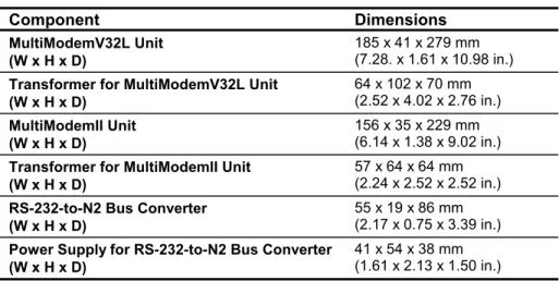
Planning considerations for the Leased Line Modem application include space, environment, and power. The space requirements are included in Table 3.
Table 3: Space Requirements
Component Dimensions
MultiModemV32L Unit (W x H x D)
185 x 41 x 279 mm (7.28. x 1.61 x 10.98 in.)
Transformer for MultiModemV32L Unit (W x H x D) 64 x 102 x 70 mm (2.52 x 4.02 x 2.76 in.) MultiModemII Unit (W x H x D) 156 x 35 x 229 mm (6.14 x 1.38 x 9.02 in.)
Transformer for MultiModemII Unit (W x H x D)
57 x 64 x 64 mm (2.24 x 2.52 x 2.52 in.)
RS-232-to-N2 Bus Converter (W x H x D)
55 x 19 x 86 mm (2.17 x 0.75 x 3.39 in.)
Power Supply for RS-232-to-N2 Bus Converter (W x H x D)
41 x 54 x 38 mm (1.61 x 2.13 x 1.50 in.)
Environment
The operating environment for the Leased Line Modem application components must maintain temperatures within the range of 0 to 50°C (32 to 122°F) while maintaining relative humidity at a value of 10 to 90% (non-condensing).
Power
The MultiModemV32L unit and the MultiModemII unit require an external power source of 115 VAC at 0.3 A (60 Hz) or 240 VAC at 0.15 A (50 Hz). Connect the modem to a circuit that is free from heavy equipment and large induction motors.
The RS-232-to-N2 Bus Converter is powered with a transformer that plugs into a 120 VAC wall outlet.
Design Considerations
Design considerations for the Leased Line Modem application include cable distances, leased line modem, and public carrier leased line capability. The allowable distances for the dedicated wire are listed in Table 4. There is no distance limitation when using public carrier leased lines.
Table 4: Cable Distances
Modem Baud Rate Allowable Distance*
MultiModemV32L Unit 9600 1.6 km (1 mile)
MultiModemII Unit 9600 1.6 km to 4.8 km
(1 to 3 miles) 14,400 0.4 km (1/4-mile)
* Longer distances are possible with lower baud rates and if the wire is not routed near noisy sources, such as fluorescent lights and power lines.
Leased Line Modem
The MultiModemV32L unit successfully passed application tests with Metasys Releases 2.02, 3.x, and 4.0. The MultiModemII (MT1432) unit successfully passed application tests with Metasys Release 4.0. The MultiModemII (MT2834) unit successfully passed application tests with Metasys Release 7.0. Other leased line modems may also work with these applications. Refer any quality or operation problems of the modem to the manufacturer.
IMPORTANT:None of these modems was qualified per
Johnson Controls environmental or noise quality standards, and are not guaranteed to work in other applications.
Public Carrier Leased Line Compatibility
The modems can be connected to 2-wire or 4-wire unconditioned private lines. The 4-wire application is more common. Refer to the
Detailed Procedures
Configuring the Modems
To configure the MultiModemV32L unit or the MultiModemII unit, you need a dumb terminal, or a terminal program such as Windows® Terminal program or ProComm Plus program running on the OWS. Connect a straight-through cable between the modem and the terminal while configuring. Leave the modem’s jumper settings (inside) to the factory default positions.
Configuring the MultiModemV32L Unit
Configuring the MultiModemV32L unit depends on which application you are using: remote OWS, remote printer, or remote N2 Bus.
Using the Remote Operator Workstation Application
To configure the MultiModemV32L unit:
1. Set the terminal to the following to enable it to configure the modems:
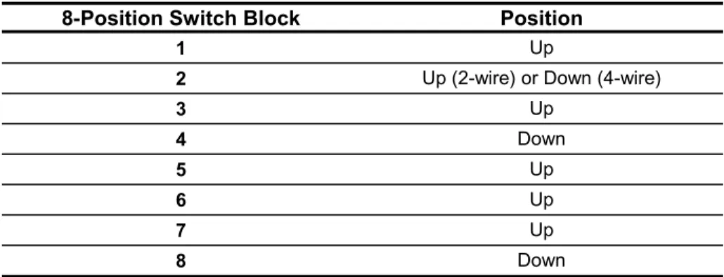
9600 baud, 0 or no parity, 8 data bits, 1 stop bit, half duplex 2. Set the modem’s switches (located on the bottom) to the following
to enable it for configuration, using Table 5 and Table 6:
Table 5: 4-Position Switch Block
4-Position Switch Block Position
1 Down
2 Down
3 Down
Table 6: 8-Position Switch Block
8-Position Switch Block Position
1 Up
2 Up (2-wire) or Down (4-wire)
3 Up 4 Down 5 Up 6 Up 7 Up 8 Down
3. Disconnect the leased line from the back of the modem, after setting the modem’s switches to enable it for programming. 4. Set the modems to 9600 baud, type the following commands,
pressing Enter after each:
AT&W1&F <Enter> ATY1Q1 <Enter> AT&E1S18=255 <Enter> AT&BSE0&W0 <Enter>
If you want to set the modems to some other acceptable baud rate (300, 600, 1200, 2400, or 4800), type the following commands, specifying the baud rate in place of xxxx. Press Enter after each command. AT&W1&F <Enter> ATY1Q1 <Enter> AT&E1S18=255 <Enter> AT$BA0$SBxxxx <Enter> AT&BS0E0&W0 <Enter>
If the modem is not communicating properly, drop the baud rate to 2400 by typing the following commands at the terminal and pressing Enter after each:
AT&W1&F <Enter> ATY1Q1 <Enter> AT&E1S18=255 <Enter> AT$BA0$SB2400 <Enter> AT$MB2400 <Enter> AT&BS0E0&W0 <Enter>
5. Cycle power on the modem. Type the following command and press Enter:
ATL5
A list of parameters displays. Verify the following parameters are in the list:
E0, Q1, &E1, $MBxxxx, $SByyyy, $BAz, &W0 where:
xxxx and yyyy = baud rate selected
z = 1 for 9600 baud; 0 for any other baud rate
If any of these parameters are incorrect, check the switch settings, reenter the command in Step 4, and verify.
6. Type the following command and press Enter: ATL7
Another parameter list displays. Verify that this list contains the following parameters:
&BS0, Y1, $MBxxxx, $SByyyy, $BAz, &W0 where:
xxxx and yyyy and z = see Step 5
Again, if any of these parameters is incorrect, check the switch settings, reenter the command in Step 4, and verify. After
verifying that the modem is properly programmed, reconnect the leased line to the modem.
7. Type the following command and press Enter: ATS18?
The response to this command should be 255. If not, reenter the command in Step 4 and verify.
8. (Optional)Specify the dialback number at the OWS’s modem (i.e., the originate modem) by typing the following command and pressing Enter, if you want to use the dialback feature:
For touchtone: ATDT<phone number>N9 For pulse: ATDP<phone number>N9 Examples:
ATDT555-1111N9 (sets 555-1111 as dialback number; uses tone dial; stores number in Location 9)
ATDP9,555-1111N9 (opens outside line; sets 555-1111 as dialback number; uses tone dial; stores number in Location 9) The 9, command in the second example opens an outside line (9) and pauses the modem for 2 seconds before it resumes dialing (,). 9. Type the following command and press Enter:
ATL
The phone number you entered should be listed under Register 9 (N9). If the number is incorrect, reenter the command in Step 8 and verify.
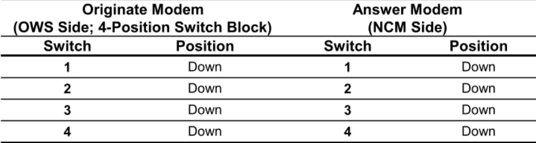
10. Change the switches to operational settings as follows to make the OWS modem the originate modem and the NCM (or JC/85 Gateway NCM) modem the answer modem, after configuring the MultiModemV32L unit. Use Table 7 or Table 8 to determine switch settings.
Table 7: 4-Position Switch Block for Originate/Answer Modems
Originate Modem
(OWS Side; 4-Position Switch Block)
Answer Modem (NCM Side)
Switch Position Switch Position
1 Down 1 Down
2 Down 2 Down
3 Down 3 Down
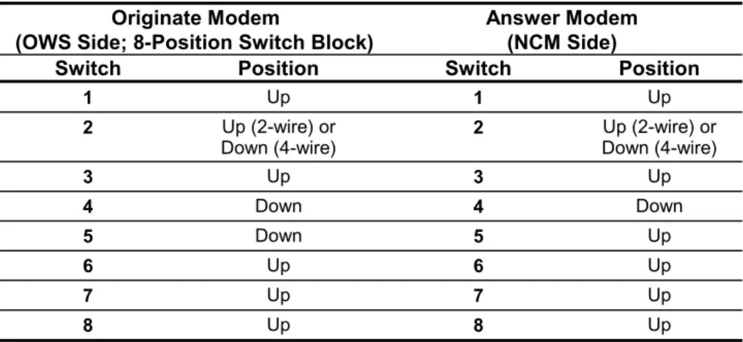
Table 8: 8-Position Switch Block for Originate/Answer Modems
Originate Modem
(OWS Side; 8-Position Switch Block)
Answer Modem (NCM Side)
Switch Position Switch Position
1 Up 1 Up
2 Up (2-wire) or
Down (4-wire) 2 Down (4-wire)Up (2-wire) or
3 Up 3 Up 4 Down 4 Down 5 Down 5 Up 6 Up 6 Up 7 Up 7 Up 8 Up 8 Up
The next step is to prepare the modem cables. Refer to Installing the Modems,Using the Remote Operator Workstation Application section.
Using the Remote Printer Application
To configure the MultiModemV32L unit:
1. Set the terminal to the following to enable it to configure the modems:
9600 baud, 0 or no parity, 8 data bits, 1 stop bit, half duplex
2. Set the modem’s switches (located on the bottom) to the settings listed in Table 9 or Table 10 to enable it for configuration:
Table 9: MultiModemV32L Unit 4-Position Switch Block
4-Position Switch Block Position
1 Down
2 Down
3 Down
Table 10: MultiModemV32L Unit 8 Position Switch Block
8-Position Switch Block Position
1 Up
2 Up (2-wire) or Down (4-wire)
3 Up 4 Down 5 Up 6 Up 7 Up 8 Down
3. Disconnect the leased line from the back of the modem, after setting the modem’s switches to enable it for programming. 4. Set the modems to 9600 baud, type the following commands,
pressing Enter after each:
AT&W1&F <Enter> AT&E5&E6Q1 <Enter> AT&E1 <Enter> ATS18=255E0&W0 <Enter>
If you want to set the modems to some other acceptable baud rate (1200, 2400, or 4800), type the following commands, specifying the baud rate in place of xxxx. Press Enter after each.
AT&W1&F <Enter> AT$BA0$SBxxxx <Enter> AT$MBxxxx&E5 <Enter> AT&E6Q1 <Enter> AT&E1S18=255E0&W0 <Enter>
These commands set certain defaults, enable error checking, and set Xon/Xoff. If the modem is not communicating properly, use a baud rate lower than 9600.
5. Cycle power on the modem. Type the following command and press Enter:
ATL5
A list of parameters displays. Verify the following parameters are in the list:
E0, Q1, &E1, &E5, &E6, $MBxxxx, $SByyyy, $BAz, &W0
where:
xxxx and yyyy = baud rate selected
If any of these parameters are incorrect, check the switch settings, reenter the command in Step 4, and verify.
6. Type the following command and press Enter: ATS18?
The response to this command should be 255. If not, reenter the command in Step 4 and verify. After verifying that the modem is properly programmed, reconnect the leased line to the modem. 7. (Optional)Specify the dialback number at the printer’s modem
(i.e., the originate modem) by typing the following command and pressing Enter, if you want to use the dialback feature:
For touchtone: ATDT<phone number>N9 For pulse: ATDP<phone number>N9 Examples:
ATDT9,555-1111N9 (opens outside line; sets 555-1111 as dialback number; uses tone dial; stores number in Location 9) ATDP555-1111N9 (sets 555-1111 as dialback number; uses pulse dial; stores number in Location 9)
The “9,” command in the first example opens an outside line (9) and pauses the modem for 2 seconds before it resumes dialing (,). 8. Type the following command and press Enter:
ATL
The phone number you entered should be listed under Register 9 (N9). If the number is incorrect, reenter the command in Step 7 and verify.
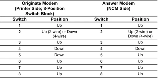
9. Change the switches to operational settings as shown in Table 11 or Table 12 to make the printer modem the originate modem and the NCM modem the answer modem, after configuring the MultiModemV32L unit.
Table 11: MultiModemV32L Unit 4-Position Operational Settings
Originate Modem (Printer Side; 4-Position
Switch Block)
Answer Modem (NCM Side)
Switch Position Switch Position
1 Down 1 Down
2 Down 2 Down
3 Down 3 Down
Table 12: MultiModemV32L Unit 8-Position Operational Settings
Originate Modem (Printer Side; 8-Position
Switch Block)
Answer Modem (NCM Side)
Switch Position Switch Position
1 Up 1 Up
2 Up (2-wire) or Down
(4-wire) 2 Up (2-wire) orDown (4-wire)
3 Up 3 Up 4 Down 4 Down 5 Down 5 Up 6 Up 6 Up 7 Up 7 Up 8 Up 8 Up
The next step is to prepare the modem cables. Refer to Using the Remote Printer Application section.
Using the Remote N2 Bus Application
To configure the MultiModemV32L unit:
1. Set the terminal to the following to enable it to configure the modems:
9600 baud, 0 or no parity, 8 data bits, 1 stop bit, half duplex
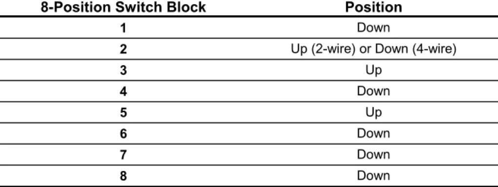
2. Set the modem’s switches (located on the bottom) to the following to enable it for configuration (Refer to Table 13 and Table 14):
Table 13: MultiModemV32L Unit 4-Position Configuration Settings
4-Position Switch Block Position
1 Up
2 Down
3 Up
Table 14: MultiModemV32L Unit 8-Position Configuration Settings
8-Position Switch Block Position
1 Down
2 Up (2-wire) or Down (4-wire)
3 Up 4 Down 5 Up 6 Down 7 Down 8 Down
3. Disconnect the leased line from the back of the modem, after setting the modem’s switches to enable it for programming. 4. Type the following commands at the terminal for each modem,
pressing Enter after each:
AT&W1&F <Enter> ATY1Q1 <Enter> AT&E0S18=255 <Enter> AT$SB9600 <Enter> AT$BA0E0&W0 <Enter>
These commands disable error correction and set certain modem defaults, such as 9600 baud.
5. Cycle power on the modem. Type the following command and press Enter:
ATL5
A list of parameters displays. Verify the following parameters are in the list:
E0, Q1, &E0, $MB9600, $SB9600, $BA0, &W0 If any of these parameters are incorrect, check the switch settings, reenter the command in Step 4, and verify.
6. Type the following command and press Enter: ATL7
Another parameter list displays. Verify that this list contains the following parameters:
Y1, $MB9600, $SB9600, $BA0, &W0
If any of these parameters is incorrect, check the switch settings, reenter the command in Step 4, and verify. After verifying that the modem is properly programmed, reconnect the leased line to the modem.
7. Type the following command and press Enter: ATS18?
The response to this command should be 255. If not, reenter the command in Step 4 and verify.
8. (Optional)Specify the dialback number at the NCM’s modem (i.e., the originate modem) by typing the following command and pressing Enter, if you want to use the dialback feature:
For touchtone: ATDT<phone number>N9 For pulse: ATDP<phone number>N9 Examples:
ATDT9,555-1111N9 (opens outside line; sets 555-1111 as dialback number; uses tone dial; stores number in Location 9) ATDP555-1111N9 (sets 555-1111 as dialback number; uses pulse dial; stores number in Location 9)
The “9,” command in the first example opens an outside line (9) and pauses the modem for 2 seconds before it resumes dialing (,). 9. Type the following command and press Enter:
ATL
The phone number you entered should be listed under Register 9 (N9). If the number is incorrect, reenter the command in Step 8 and verify.
10. Change the MultiModem V32L switches to operational settings to those listed in Table 15 or Table 16 to make the NCM modem the originate modem and the N2 device modem the answer modem, after configuring the MultiModemV32L unit.
Table 15: MultiModemV32L Unit 4-Position Switch Block Settings
Originate Modem (NCM; 4-Position Switch Block)
Answer Modem (N2 Device Side) Switch Position Switch Position
1 Up 1 Up
2 Down 2 Down
3 Up 3 Up
Table 16: MultiModemV32L Unit 8-Position Switch Block Settings Originate Modem (NCM Side; 8-Position Switch Block) Answer Modem (N2 Device Side) Switch Position Switch Position
1 Down 1 Down
2 Up (2-wire) or
Down (4-wire) 2 Up (2-wire) orDown (4-wire)
3 Up 3 Up 4 Down 4 Down 5 Down 5 Up 6 Down 6 Down 7 Down 7 Down 8 Up 8 Up
The next step is to prepare the modem cables. Refer to Installing the Modems, Using the Remote N2 Bus Application section.
Configuring the MultiModemII (MT1432A) Unit
Configuring the MultiModemII (MT1432) unit depends on which application you are using: remote OWS, remote printer, or remote N2 Bus.
Note: If you are configuring the MultiModemII (MT1932 or MT2834) unit, refer to the section, Configuring the
MultiModemII (MT1932 and MT2834) Unit.
Using the Remote Operator Workstation Application
To configure the MultiModemII (MT1432) unit:
1. Set the terminal to the following to enable it to configure the modems:
9600 baud, 0 or no parity, 8 data bits, 1 stop bit, half duplex
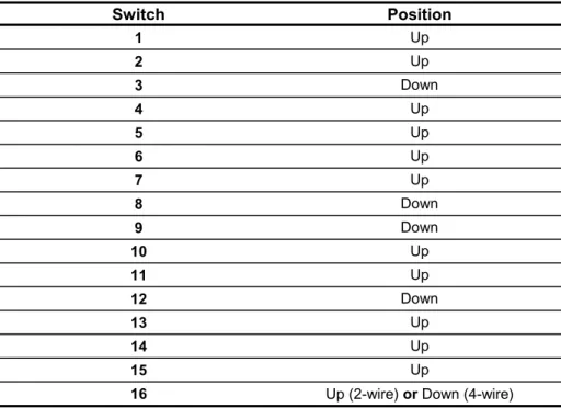
2. Set the modem’s switches (located on the side) to the following to enable it for configuration:
Table 17: MultiModemII MT1432 Unit Switch Settings Switch Position 1 Up 2 Up 3 Down 4 Up 5 Up 6 Up 7 Up 8 Down 9 Down 10 Up 11 Up 12 Down 13 Up 14 Up 15 Up
16 Up (2-wire) or Down (4-wire)
3. Disconnect the leased line from the back of the modem, after setting the modem’s switches to enable it for programming. 4. Set the modem’s serial port to 9600 bps and the modem’s leased
line to 14.4 Kbps, type the following commands, pressing Enter after each:
AT&W1&F <Enter> AT$SB9600S18=255 <Enter> AT&E1&BS0 <Enter> ATY1Q1E0&W0 <Enter>
If you want to set the modem’s serial port to some other acceptable baud rate (300, 600, 1200, 2400, etc.), type the following command, specifying the baud rate in place of xxxx. Press Enter.
AT$SBxxxx&W0 <Enter>
If the modems are not communicating properly, drop the leased line baud rate to 9600 (or less) by typing the following command at the terminal and pressing Enter:
AT$MB9600&W0 <Enter>
Then, set Switches 13 and 14 (baud rate) appropriately. (See the owner’s manual.)
5. Cycle power on the modem. Type the following command and press Enter:
ATL5
A list of parameters displays. Verify the following parameters are in the list:
E0, Q1, &E1, $SBxxxx, &W0 where:
xxxx = baud rate selected
If any of these parameters are incorrect, check the switch settings, reenter the command in Step 4, and verify.
6. Cycle power on the modem. Type the following command and press Enter:
ATL7
A list of parameters displays. Verify the following parameters are in the list:
&BS0, Y1, $SBxxxx, &W0 where:
xxxx = baud rate selected
If any of these parameters is incorrect, reenter the commands in Step 4 and verify. After verifying that the modem is properly programmed, reconnect the leased line to the modem.
7. Type the following command and press Enter: ATS18?
The modem should respond with 255. If not, reenter the commands in Step 4 and verify.
8. (Optional)Specify the dialback number at the OWS’s modem (i.e., the originate modem) by typing the following command and pressing Enter, if you want to use the dialback feature:
For touchtone: ATDT<phone number>N9 For pulse: ATDP<phone number>N9 Examples:
ATDT9,555-1111N9 (opens outside line; sets 555-1111 as dialback number; uses tone dial; stores number in Location 9) ATDP555-1111N9 (sets 555-1111 as dialback number; uses pulse dial; stores number in Location 9)
The “9,” command in the first example opens an outside line (9) and pauses the modem for 2 seconds before it resumes dialing (,).
9. Type the following command and press Enter: ATL
The phone number you entered should be listed under Register 9 (N9). If the number is incorrect, reenter the command in Step 8 and verify.
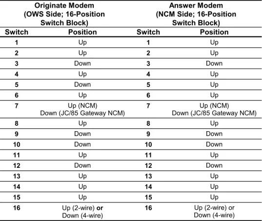
10. Change the MultiModemII (MT1432) switches to operational settings as shown in Table 18 to make the OWS modem the originate modem and the NCM (or JC/85 Gateway NCM) modem the answer modem, after configuring the MultiModemII
(MT1432) unit.
Table 18: MultiModemII MT1432 Unit Originate/Answer Settings
Originate Modem (OWS Side; 16-Position
Switch Block)
Answer Modem (NCM Side; 16-Position
Switch Block) Switch Position Switch Position
1 Up 1 Up 2 Up 2 Up 3 Down 3 Down 4 Up 4 Up 5 Down 5 Up 6 Up 6 Up 7 Up (NCM)
Down (JC/85 Gateway NCM) 7 Down (JC/85 Gateway NCM)Up (NCM)
8 Up 8 Up 9 Down 9 Down 10 Down 10 Down 11 Up 11 Up 12 Down 12 Down 13 Up 13 Up 14 Up 14 Up 15 Up 15 Up 16 Up (2-wire) or Down (4-wire) 16 Up (2-wire) or Down (4-wire)
The next step is to prepare the modem cables. Refer to Using the Remote Operator Workstation Application section.
Using the Remote Printer Application
To configure the MultiModemII (MT1432, MT1932, or MT2834) unit: 1. Set the terminal to the following to enable it to configure the
modems:
9600 baud, 0 or no parity, 8 data bits, 1 stop bit, half duplex
2. Set the modem’s switches (located on the side) to the following to enable it for configuration:
Table 19: MultiModemII Unit Configuration Settings
Switch Position 1 Up 2 Down 3 Down 4 Up 5 Up 6 Up 7 Up 8 Down 9 Down 10 Up 11 Up 12 Down 13 Up 14 Up 15 Up 16 Up (2-wire) or Down (4-wire)
3. After setting the modem’s switches to enable it for programming, disconnect the leased line from the back of the modem.
4. Set the modem’s serial port to 9600 bps and the modem’s leased line to 9600 bps, type the following commands, pressing Enter after each:
AT&W1&F <Enter> AT$SB9600S18=255 <Enter> AT&E5&E7 <Enter> AT&E1Q1E0&W0 <Enter>
If you want to set the modem’s serial port to some other acceptable baud rate (300, 600, 1200, etc.), type the following command, specifying the baud rate in place of xxxx. Press Enter. AT$SBxxxx&W0
If the modem is not communicating properly, drop the leased line baud rate to 9600 (or less) by typing the following command at the terminal and pressing Enter:
AT$MB9600&W0
Then, set Switches 13 and 14 (baud rate) appropriately. (See the owner’s manual.)
5. Cycle power on the modem. Type the following command and press Enter:
ATL5
A list of parameters displays. Verify the following parameters are in the list:
E0, Q1, &E1, &E5, &E7, $SBxxxx, &W0 where:
xxxx and yyyy = baud rate selected
If any of these parameters are incorrect, check the switch settings, reenter the command in Step 4, and verify.
6. Type the following command and press Enter: ATS18?
The modem should respond with 255. If not, reenter the
commands in Step 4 and verify. After verifying that the modem is properly programmed, reconnect the leased line to the modem. 7. (Optional) If you want to use the dialback feature, specify the
dialback number at the printer’s modem (i.e., the originate modem) by typing the following command and pressing Enter: For touchtone: ATDT<phone number>N9
For pulse: ATDP<phone number>N9 Examples:
ATDT9,555-1111N9 (opens outside line; sets 555-1111 as dialback number; uses tone dial; stores number in Location 9) ATDP555-1111N9 (sets 555-1111 as dialback number; uses pulse dial; stores number in Location 9)
The “9,” command in the first example opens an outside line (9) and pauses the modem for 2 seconds before it resumes dialing (,).
8. Type the following command and press Enter: ATL
The phone number you entered should be listed under Register 9 (N9). If the number is incorrect, reenter the command in Step 7 and verify.
9. After configuring the MultiModemII (MT1432, 1932, or MT2834) unit, change its switches to operational settings as shown in
Table 20 to make the printer modem the originate modem and the NCM modem the answer modem.
Table 20: MultiModemII Unit Originate/Answer Settings
Originate Modem (Printer Side; 16-Position
Switch Block)
Answer Modem (NCM Side)
Switch Position Switch Position
1 Up 1 Up 2 Down 2 Down 3 Down 3 Down 4 Up 4 Up 5 Down 5 Up 6 Up 6 Up 7 Up 7 Up 8 Up 8 Up 9 Down 9 Down 10 Up 10 Up 11 Up 11 Up 12 Down 12 Down 13 Up 13 Up 14 Up 14 Up 15 Up 15 Up 16 Up (2-wire) or Down (4-wire) 16 Up (2-wire) or Down (4-wire)
The next step is to prepare the modem cables. Refer to Using the Remote Printer Application section.
Using the Remote N2 Bus Application
To configure the MultiModemII (MT1432) unit:
1. Set the terminal to the following to enable it to configure the modems:
9600 baud, 0 or no parity, 8 data bits, 1 stop bit, half duplex
2. Set the modem’s switches (located on the side) to the following to enable it for configuration:
Table 21: MultiModemII MT1432 Unit Configuration Settings
Switch Position 1 Down 2 Up 3 Down 4 Up 5 Up 6 Up 7 Down 8 Down 9 Down 10 Up 11 Up 12 Down 13 Down 14 Up 15 Down 16 Up (2-wire) or Down (4-wire)
3. After setting the modem’s switches to enable it for programming, disconnect the leased line from the back of the modem.
4. Set the modem’s serial port to 9600 bps and the modem’s leased line to 14.4 Kbps, type the following commands, pressing Enter after each:
AT&W1&F <Enter> AT$SB9600S18=255 <Enter> AT&E0$MB9600 <Enter> ATY1Q1E0&W0 <Enter>
5. Cycle power on the modem. Type the following command and press Enter:
ATL5
A list of parameters displays. Verify the following parameters are in the list:
E0, Q1, &E0, $MB9600, $SB9600, &W0
If any of these parameters are incorrect, check the switch settings, reenter the command in Step 4, and verify.
6. Cycle power on the modem. Type the following command and press Enter:
ATL7
A list of parameters displays. Verify the following parameters are in the list:
Y1, $MB9600, $SB9600, &W0
If any of these parameters is incorrect, check the switch settings, reenter the four commands in Step 4, and verify. After verifying that the modem is properly programmed, reconnect the leased line to the modem.
7. Type the following command and press Enter: ATS18?
The modem should respond with 255. If not, reenter the four commands in Step 4 and verify.
8. (Optional) If you want to use the dialback feature, specify the dialback number at the NCM’s modem (i.e., the originate modem) by typing the following command and pressing Enter:
For touchtone: ATDT<phone number>N9 For pulse: ATDP<phone number>N9 Examples:
ATDT9,555-1111N9 (opens outside line; sets 555-1111 as dialback number; uses tone dial; stores number in Location 9) ATDP555-1111N9 (sets 555-1111 as dialback number; uses pulse dial; stores number in Location 9)
The “9,” command in the first example opens an outside line (9) and pauses the modem for 2 seconds before it resumes dialing (,).
9. Type the following command and press Enter: ATL
The phone number you entered should be listed under Register 9 (N9). If the number is incorrect, reenter the command in Step 8 and verify.
10. After configuring the MultiModemII (MT1432) unit, change its switches to operational settings as shown in Table 22 to make the NCM modem the originate modem and the N2 device modem the answer modem.
Table 22: MultiModemII (MT1432) Unit Originate/Answer Settings
Originate Modem
(NCM Side; 16-Position Switch Block)
Answer Modem (N2 Device Side) Switch Position Switch Position
1 Down 1 Down 2 Up 2 Up 3 Down 3 Down 4 Up 4 Up 5 Down 5 Up 6 Up 6 Up 7 Down 7 Down 8 Up 8 Up 9 Down 9 Down 10 Up 10 Up 11 Up 11 Up 12 Down 12 Down 13 Down 13 Down 14 Up 14 Up 15 Down 15 Down 16 Up (2-wire) or
Down (4-wire) 16 Up (2-wire) Down (4-wire)or
The next step is to prepare the modem cables. Refer to Using the Remote N2 Bus Application section.
Configuring the MultiModemII (MT1932 and MT2834) Unit
Configuring the MultiModemII (MT1932 and 2834) unit depends on which application you are using: remote OWS, remote printer, or remote N2 Bus.
Using the Remote Operator Workstation Application
To configure the MultiModemII (MT1932 or MT2834) unit: 1. Set the terminal to the following to enable it to configure the
modems:
9600 baud, 0 or no parity, 8 data bits, 1 stop bit, half duplex
2. Make sure the modem’s switches (located on the side) are set to the following default positions as shown in Table 23 to enable it for configuration.
Table 23: MultiModemII (MT1932 and MT2834) Unit Configuration Settings
Switch Default Position
1 Up 2 Up 3 Down 4 Up 5 Up 6 Up 7 Down 8 Down 9 Down 10 Up 11 Down 12 Down 13 Up 14 Up 15 Up 16 Up (2-wire) or Down (4-wire)
3. After setting the modem’s switches to enable it for programming, disconnect the leased line from the back of the modem.
4. Set the modem’s serial port to 9600 bps and the modem’s leased line to 19.2 Kbps, type the following commands, pressing Enter after each:
AT&W1&F <Enter> AT$SB9600S18=255 <Enter> AT&E1&BS0 <Enter> ATY0Q1E0&W0 <Enter>
If you want to set the modem’s serial port to some other acceptable baud rate (300, 600, 1200, 2400, etc.), type the following command, specifying the baud rate in place of xxxx. Press Enter.
AT$SBxxxx&W0 <Enter>
If the modems are not communicating properly, drop the leased line baud rate to 9600 (or less) by typing the following command at the terminal and pressing Enter:
AT$MB9600&W0 <Enter>
Then, set Switches 13 and 14 (baud rate) appropriately. (See the owner’s manual.)
5. Cycle power on the modem. Type the following command and press Enter:
ATL5
A list of parameters displays. Verify the following parameters are in the list:
E0, Q1, &E1, $SBxxxx, &W0 where:
xxxx = baud rate selected
If any of these parameters is incorrect, check the switch settings, reenter the commands in Step 4, and verify.
6. Cycle power on the modem. Type the following command and press Enter:
ATL7
A list of parameters displays. Verify the following parameters are in the list:
&BS0, Y0, $SBxxxx, &W0 where:
If any of these parameters is incorrect, reenter the commands in Step 4 and verify. If any of these parameters are incorrect, check the switch settings, reenter the command in Step 4, and verify. After verifying that the modem is properly programmed, reconnect the leased line to the modem.
7. Type the following command and press Enter: ATS18?
The modem should respond with 255. If not, reenter the commands in Step 4 and verify.
8. (Optional) If you want to use the dialback feature, specify the dialback number at the OWS’s modem (i.e., the originate modem) by typing the following command and pressing Enter:
For touchtone: ATDT<phone number>N9 For pulse: ATDP<phone number>N9 Examples:
ATDT9,555-1111N9 (opens outside line; sets 555-1111 as dialback number; uses tone dial; stores number in Location 9) ATDP555-1111N9 (sets 555-1111 as dialback number; uses pulse dial; stores number in Location 9)
The “9,” command in the first example opens an outside line (9) and pauses the modem for 2 seconds before it resumes dialing (,). 9. Type the following command and press Enter:
ATL
The phone number you entered should be listed under Register 9 (N9). If the number is incorrect, reenter the command in Step 8 and verify.
10. After configuring the MultiModemII (MT1932 or MT2834) unit, change its switches to operational settings as shown in Table 24 to make the OWS modem the originate modem and the NCM
Table 24: MultiModemII (MT1932 and MT2834) Unit Originate/Answer Settings
Originate Modem (OWS Side; 16-Position
Switch Block)
Answer Modem (NCM Side; 16-Position
Switch Block)
Switch Position Switch Position
1 Up 1 Up 2 Up 2 Up 3 Down 3 Down 4 Up 4 Up 5 Down 5 Up 6 Up 6 Up 7 Up (NCM)
Down (Gateway NCM) 7 Down (Gateway NCM)Up (NCM)
8 Up 8 Up 9 Down 9 Down 10 Down 10 Down 11 Up 11 Up 12 Down 12 Down 13 Up 13 Up 14 Up 14 Up 15 Up 15 Up 16 Up (2-wire) or Down (4-wire) 16 Up (2-wire) or Down (4-wire)
The next step is to install the modem. Refer to Using the Remote Operator Workstation Application section.
Using the Remote Printer Application
The steps for configuring the MultiModemII (MT1932 or MT2834) unit for the remote printer application are the same as for the MT1432 model. Refer to the Configuring theMultiModemII (MT1432) Unit, Using the Remote Printer Application section.
Using the Remote N2 Bus Application
The configuration setup for the MT1932 and MT2834BL 4-wire leased line modem and the MT2834BA 2-wire leased line modem is the same with one exception. When configuring the MT1932 or MT2834BA, ignore the “S18=255” parameter in Step 3.
To configure the MultiModemII (MT1932 and MT2834) unit: 1. Set the terminal to the following to enable it to configure the
modems:
9600 baud, 0 or no parity, 8 data bits, 1 stop bit, half duplex
2. Set the modem’s switches (located on the side) to the following as shown in Table 25 to enable it for configuration:
Table 25: MultiModemII MT1932 and MT2834 Unit Configuration Settings Switch Position 1 Up 2 Up 3 Down 4 Up 5 Up 6 Up 7 Down 8 Down 9 Down 10 Up 11 Down 12 Down 13 Down 14 Down 15 Down 16 Up (2-wire) or Down (4-wire)
3. After setting the modem’s switches to enable it for programming, disconnect the leased line from the back of the modem.
4. Set the modem’s serial port to 9600 bps and the modem’s leased line to 9600 bps, type the following commands, pressing Enter after each:
AT&W1&F <Enter> AT$SB9600S18=255 <Enter> AT&E0$MB9600#F0 <Enter> ATY0Q1E0&W0 <Enter>
5. Cycle power on the modem. Type the following command and press Enter:
ATL5
A list of parameters displays. Verify the following parameters are in the list:
E0, Q1, &E0, $MB9600, $SB9600, &W0
If any of these parameters is incorrect, check the switch settings, reenter the four commands in Step 4, and verify.
6. Cycle power on the modem. Type the following command and press Enter:
ATL7
A list of parameters displays. Verify the following parameters are in the list:
Y0, $MB9600, #F0 $SB9600, &W0
If any of these parameters are incorrect, check the switch settings, reenter the command in Step 4, and verify. After verifying that the modem is properly programmed, reconnect the leased line to the modem.
7. Type the following command and press Enter: ATS18?
The modem should respond with 255. If not, reenter the four commands in Step 4 and verify.
8. (Optional) If you want to use the dialback feature, specify the dialback number at the NCM’s modem (i.e., the originate modem) by typing the following command and pressing Enter:
For touchtone: ATDT<phone number>N9 For pulse: ATDP<phone number>N9 Examples:
ATDT9,555-1111N9 (opens outside line; sets 555-1111 as dialback number; uses tone dial; stores number in Location 9) ATDP555-1111N9 (sets 555-1111 as dialback number; uses pulse dial; stores number in Location 9)
The “9,” command in the first example opens an outside line (9) and pauses the modem for 2 seconds before it resumes dialing (,).
9. Type the following command and press Enter: ATL
The phone number you entered should be listed under Register 9 (N9). If the number is incorrect, reenter the command in Step 8 and verify.
10. After configuring the MultiModemII (MT 1932 and MT2834) unit, change its switches to operational settings as shown in Table 26 to make the NCM modem the originate modem and the N2 device modem the answer modem.
Table 26: MultiModemII (MT1932 and MT2834) Unit Operational Settings
Originate Modem
(NCM Side; 16-Position Switch Block)
Answer Modem (N2 Device Side) Switch Position Switch Position
1 Down 1 Down 2 Up 2 Up 3 Down 3 Down 4 Up 4 Up 5 Down 5 Up 6 Up 6 Up 7 Down 7 Down 8 Up 8 Up 9 Down 9 Down 10 Down 10 Down 11 Up 11 Up 12 Down 12 Down 13 Down 13 Down 14 Down 14 Down 15 Down 15 Down 16 Up (2-wire) or
Down (4-wire) 16 Up (2-wire) Down (4-wire)or
The next step is to install the modem. Refer to Using the Remote N2 Bus Application section.
Using Commissioning Procedures
Verifying Modems are Working
When the modems are working properly, the TR and CD lights are on steady, and the appropriate baud rate lights are on (remote N2
application) or flashing (remote OWS or printer application;
MultiModemV32L unit only). Also, the SD and RD lights are blinking to indicate that data is being transferred. If any of the lights are not working in these ways, refer to the Troubleshooting Procedures
section for assistance.
Checking the Dialback Line
If you are using the dialback line, verify its operation. Force the modem to switch to the dialback line by pressing down and releasing the Voice/Data switch on the originate modem and disconnecting the leased line. The originate modem disconnects from the answer modem and calls the modem on the dialback line. If the modem on the
dialback line does not answer within the prescribed time period, the originate modem defaults to the modem on the leased line.
To return the modem to leased line operation, reconnect the leased line and press the Voice/Data switch down again. The originate modem disconnects from the modem on the dialback line and reconnects to the modem on the leased line. At this point, a communication bug in the modem may cause an interruption in communication. (For details, refer to the Troubleshooting Procedures section.) To verify the bug is cleared and the modem reset, simply cycle power on the originate
modem.
If for any reason you press down on the Voice/Data switch on the answer modem, the answer modem disconnects the line that is currently being used. The originate modem then attempts
communication over the leased line first, then the dialback line. The modem continues to toggle between the 2 lines until it makes a connection.
Installing the Modems
After you have configured the modems, the next step is to prepare and connect modem cables. Which cables to prepare and how to connect them depends on which application you are using: remote OWS, remote printer, or remote N2 Bus. Refer to the sections that follow.
Using the Remote Operator Workstation Application
To make the modem cables:
1. Prepare the cable that connects between the serial port and the modem, if you are using the NCM’s RS-232 serial port. For the NCM101/102/401/200, refer to Figure 5. For the NCM300, refer to Figure 6. Because of the recessed connector on the
NCM101/102/401/200, a special right-angle cable with a narrow profile shell is required to attach to the RS-232 port
(NU-CBL101-0). Connect the pigtailed wires of this cable into a separately ordered hood (MHK101).
Note: For additional information on the NCM300, refer to the
Network Control Module 300 Series Technical Bulletin (LIT-6360251). Out In Out 1 2 3 4 5 6 7 8 18 20 FG TD Black RD Brown RTS Red CTS Orange DSR Yellow SG Green DCD Blue DTR White DCE DCD Violet NCM RS-232 Port Modem (male) (male) In Out In Out Out In Out Out In 1 2 3 4 5 6 7 8 18 20 In NCPT-MOD Out
Figure 5: Cable Between NCM101/102/401/200’s RS-232 Port and Modem (NU-CBL101-0)
1 2 3 4 5 6 7 8 9 DCD RD TD DTR SG DSR RTS CTS NC NCM300 9-pin Female 2 3 4 5 6 7 8 20 Modem or System Adapter 25-pin Male Shell NC3FIG9 Shell In In Out Out In Out In In Out In Out Out Out In
Figure 6: Cable Between NCM300’s Port 2 (RS-232) and Modem
If you are using the RS-232 submodule, prepare the RS-232 cable (NU-CBL101-0) shown in Figure 7. This cable connects between the submodule and modem.
RS-232 Submodule (male) Modem (male) Out Out Out Out Out Out Out In In In In In In In 1 2 3 4 5 6 7 8 18 20 Shell 2 3 4 5 6 7 8 18 20 FG TD Black RD Brown RTS Red CTS Orange DSR Yellow SG Green DCD Blue DTR White Unused Violet Out In In RS2-MOD1
Figure 7: Cable Between NCM’s RS-232 Submodule and Modem (NU-CBL101-0)
2. Prepare the RS-232 cable that connects between the PS/2 OWS and the modem (if you have a PS/2). The pinouts are shown in Figure 8. Out Out Out Out Out Out Out In In In In In In In 1 2 3 4 5 6 7 8 18 20 Shell 2 3 4 5 6 7 8 18 20 FG TD Black RD Brown RTS Red CTS Orange DSR Yellow SG Green DCD Blue DTR White Unused Violet (male) Modem (male) Out In In PS/2 Operator Workstation RS2-MOD2
Allied Part No. CON94-3870-10
Figure 8: Cable Between PS/2 Operator Workstation and Modem
If you have a Compaq Deskpro or Compaq portable, prepare the RS-232 cable that connects between the Compaq or portable Workstation and the modem. The pinouts are shown in Figure 9.
Shell 1 2 3 4 5 6 7 8 9 2 3 4 5 6 7 8 20 22 Shell Compaq or Portable Workstation (9-pin female) Modem (25-pin male) Out In In In In Out Out Out Out In In In Out Out COM Out PORT-MOD In FG
Allied Part No. CON94-3856-6
Figure 9: Cable Between Compaq or Portable Workstation and Modem
Preparing Modem Cables for JC/85 Gateway
If you are using the leased line modems for a JC/85 Gateway application, prepare the cable required to connect the JC/85/40
minicomputer (CPU-101/-110/-112) and the leased line modem (either model) See Figure 10.
Out In Out 1 2 3 4 5 6 7 12 16 20 22 FG TD Black RD Brown CTS Red RTS Orange DTR Yellow SG Green Speed Blue DCD White Unused Violet JC/85/40 CPU-101/110/112 PCA-110 MultiTech Leased Line Modem
(male) (male) Out In In Out Out In Out 1 2 3 5 4 20 7 12 13 6 8 CABLE1 In DSR Gray In Out In In
Cable Application No. C02.M06
Figure 10: Cable Between JC/85/40 CPU-101/110/112 and Modem
To prepare the modem cables:
1. Prepare the cable required to connect the JC/85/40 minicomputer (CPU-111/-113) and the leased line modem (either model) as shown in Figure 11.
Out In 1 2 3 4 5 6 7 8 20 14 13 FG TD Black RD Brown RTS Red CTS Orange DSR Yellow SG Green DCD Blue Unused White DTR Violet JC/85/40 CPU-111/113 2/4 Channel MultiTech Leased Line Modem
(male) (male) Out In 1 2 3 4 5 8 7 6 20 14 13 CABLE2 In Unused Gray
Cable Application No. C03.M02 Out In In Out In Out Out Out In
Figure 11: Cable Between JC/85/40 CPU-111/113 and Modem
2. Prepare the cable required between the JC/85 Gateway NCM and the leased line modem (either model) as shown in Figure 12.
Out Out Out Out Out Out Out In In In In In In In 1 2 3 4 5 6 7 8 18* 20 Shell 2 3 4 5 6 7 8 18* 20 FG TD Black RD Brown RTS Red CTS Orange DSR Yellow SG Green DCD Blue DTR White Unused Violet JC/85 Gateway NCM (RS-232 Submodule) (male) MultiTech Leased Line Modem
(male)
CABLE3
Cable Application No. C07.M07
If you are using MultiTech MultiModem V32L, cut Pin 18 at the modem end.
*
RESET (either or) RS-232 Submodule Port NCM RS-232 Port Modem To Dialback Line To Power To Power Operator Workstation Serial Modem To Dialback Line To Leased Line
(or Dedicated Line)
To Leased Line
(or Dedicated Line) OWSCONN
For NCM300, RS-232 connection is made at Port 2. (RS-232 port).
Note:
Figure 13: Connecting the Cables for Remote Operator Workstation
Connecting the Cables
To connect the cables, referring to Figure 13.
1. Connect the serial port and the modem with the cable shown in Figure 5, if you are using the NCM’s RS-232 serial port. (For the NCM300, connect the cable shown in Figure 6 between the NCM’s Port 2 and the modem.)
If you are using the RS-232 submodule, connect the cable shown in Figure 7 between the submodule and the modem.
2. Connect the RS-232 cable between the modem and the OWS’s serial port (i.e., same serial port used for direct connect). The RS-232 cable is shown in Figure 5 or Figure 7.
3. Plug in one end of the RJ11 cable for the leased line into the Leased Line connector, for each modem, and the other end into the modular phone jack provided by the telephone company. If you are using dedicated wire instead of leased line, route and terminate the dedicated wire to the Leased Line connector.
4. (Optional)Plug in one end of the RJ11 cable for the standard telephone line into the Dial Line connector, and the other end into the modular phone jack provided by the telephone company, if you are using the dialback feature. Do this for each modem. 5. Plug the AC power transformer into the Power connection, for
each modem. Turn on the modems by flipping the On/Off switch to On.
The modems now run diagnostic self-tests. (The speed indicators flash.) If the OWS and the NCM are on, the TR light and one or more of the baud rate lights come on. Then, after about 30 seconds, the CD light goes on, and the appropriate baud rate lights flash
(MultiModemV32L unit) or go on steady (MultiModemII unit). If these lights remain off, refer to the modem owner’s manual.
Using the Remote Printer Application
Preparing Modem Cables
To make the modem cables.
1. Prepare the cable that connects between the serial port and the modem, if you are using the NCM’s RS-232 serial port. For the NCM101/102/401/200, refer to Figure 5. For the NCM300, refer to Figure 6. Because of the recessed connector on the
NCM101/102/401/200, a special right-angle cable with a narrow profile shell is required to attach to the RS-232 port
(NU-CBL101-0). Connect the pigtailed wires of this cable into a separately ordered hood (MHK101).
If you are using the RS-232 submodule, prepare the RS-232 cable (NU-CBL101-0) shown in Figure 7. This cable connects between the submodule and modem.
2. Prepare the RS-232 cable that connects between the modem and the printer (Figure 14). This is a straight-through, 25-to-25 pin cable. A minimum of Pins 2, 3, 4, 5, 6, 7, 8, and 20 is required.
Out Out Out Out Out Out Out In In In In In In In 1 2 3 4 5 6 7 8 18 20 Shell 2 3 4 5 6 7 8 18 20
IBM Proprinter III (male; MHK 101) FG TD Black RD Brown RTS Red CTS Orange DSR Yellow SG Green DCD Blue DTR White Modem (male) Unused Violet MOD-PRT R
Figure 14: Cable Between Modem and Printer (NU-CBL101-0)
Connecting the Cables
To connect the cables, referring to Figure 14.
1. Connect the cable shown in Figure 5 between the serial port and the modem, if you are using the NCM’s RS-232 serial port,. (For the NCM300, connect the cable shown Figure 6 between the NCM’s Port 2 and the modem.)
If you are using the RS-232 submodule, connect the cable shown in Figure 7 between the submodule and the modem.
2. Connect the RS-232 cable shown in Figure 14 between the printer and the modem.
3. Plug in one end of the RJ11 cable for the leased line into the Leased Line connector, and the other end into the modular phone jack provided by the telephone company, for each modem. If you are using dedicated wire instead of leased line, route and terminate the dedicated wire to the Leased Line connector.
4. (Optional)Plug in one end of the RJ11 cable for the standard telephone line into the Dial Line connector, and the other end into the modular phone jack provided by the telephone company, if you are using the dialback feature. Do this for each modem. 5. Plug the AC power transformer into the Power connection, for
each modem. Turn the modems on.
The modems now run diagnostic self-tests. (The speed indicators flash.) If the printer and the NCM are on, the TR light and one or more of the baud rate lights come on. Then, after about 30 seconds, the CD light goes on, and the appropriate baud rate lights flash
(MultiModemV32Lunit ) or go on steady (MultiModemII unit). If these lights remain off, refer to the modem owner’s manual.
Modem
To Power To Power
Modem
To Dialback Line To Leased Line
(or Dedicated Line) (either or)
RS-232 Submodule Port
To Dialback Line To Leased Line
(or Dedicated Line) prntconn
RESET NCM RS-232 Port Printer Serial For NCM300, RS-232 connection is made at Port 2.
(RS-232 port). Note:
Using the Remote N2 Bus Application
B & B RS-232 to RS-485 Converter
Follow these instructions to use the RS-232 to RS-485 converter (Model 485TBLED manufactured by B & B Electronics): There are two jumpers on the B & B converter (Figure 16).
1. Insert one jumper in the CONTROL SD location and insert the other jumper in the ECHO OFF location. The SD position causes a timed internal Request to Send (RTS) signal to be generated when the TD signal is active.
2. Insert an external 100 ohm resistor between the GND terminal and the N2 cable reference wire.
Note: The external power supply common is also connected to the GND terminal. No connection is made to the
FR GND SHIELD terminal on the B & B converter. 3. Connect Terminals TD(A) and RD(A) together with an external
jumper wire: This is the N2- line connection point. Connect Terminals TD(B) and RD(B) together with an external jumper wire. This is the N2+ connection point.
TB1 FR.GND SHIELD TD(A) TD(B) RD(A) RD(B) GND +12VDC N2-N2+ REF. 100 ohm ECHO CONTROL OFF ON RTS SD C6 R9 B & B Electronics Model 485TBLED 485PS2 bbcvt Converter RS-232 to RS-485 RS-485 RS-232
There is no need for an End-of-Line Resistor (EOLR) when using the B & B converter. B & B converters produce an N2 bias, which exceeds the 0.4 V stated in the Troubleshooting Procedures section of the
N2 Communications Bus Technical Bulletin (LIT-636018). The
Metasys system devices already provide the necessary N2 drive power.
If you exceed 32 devices on either the remote or the local trunk, insert an N2 repeater after 32 devices instead of after the normal 50 devices. For more information on the N2, refer to the
N2 Communications Bus Technical Bulletin (LIT-636018).
Note: When baseframe equipment (DCM, XRE, XRL, XRM, XBN) is used at the remote end, special timing is required on the converter that attaches to that equipment. The converter turnaround time must be faster to work with these devices. Resistor R9 must be changed from the standard 100 K ohm to a 68 K ohm, 1%, 1/8 watt resistor. B & B Electronics provides this change. Order a “*modification line item: change R9 to a 68 K ohm, 1% resistor” when placing your order.
Preparing Modem Cables
To make the modem cables:
1. Prepare the RS-232 cable that connects between the RS-232 submodule and the modem, if you are using the NCM’s RS-232 submodule. The pinouts are shown Figure 17. Because of the recessed connector on the NCM, a special right-angle cable with a narrow profile shell is required to attach to the RS-232 port (NU-CBL101-0). Connect the pigtailed wires of this cable into a separately ordered hood (MHK101).
RS-232 Submodule (male) Modem (male) Out Out Out Out Out Out Out In In In In In In In 1 2 3 4 5 6 7 8 18 20 Shell 2 3 4 5 6 7 8 18 20 FG TD Black RD Brown RTS Red CTS Orange DSR Yellow SG Green DCD Blue DTR White Unused Violet Out In In RS2-MOD1
Figure 17: Cable Between NCM’s RS-232 Submodule and Modem (NU-CBL101-0)
2. Prepare the RS-232 cable that connects between the RS-232-to-N2 Bus converter and the modem, if you are using the N2 converter. The pinouts are shown in Figure 18.
Out In FG TD Black RD Brown Modem (male) In Out In SG 1 2 3 4 7 1 2 3 4 7 Converter (male) MOD-CNTR
Figure 18: Cable Between Converter and Modem (NU-CBL101-0)
Connecting the N2 Bus and Modems
Follow these instructions, referring to Figures 17, 18, and 19.
1. Connect the RS-232 cable that is shown in Figure 17 between the submodule and the modem, if you are using the RS-232
submodule.
If you are not using the RS-232 submodule, wire the N2 Bus between the Communication Terminal Board (TBC) on the NCU (or N2 terminal block on the NCM300) and the converter
(Figures 20 and 21).
2. Connect the RS-232 cables shown in Figure 18 between the modem and the converter.
3. Connect the converter to the N2 Bus.
4. Plug in one end of the RJ11 cable for the leased line into the Leased Line connector, and the other end into the modular phone jack provided by the telephone company, for each modem. If you are using dedicated wire instead of leased line, route and terminate the dedicated wire to the Leased Line connector.
5. (Optional)Plug in one end of the RJ11 cable for the standard telephone line into the Dial Line connector, and the other end into the modular phone jack provided by the telephone company, if you are using the dialback feature. Do this for each modem. 6. Plug the AC power transformer into the Power connection, for
each modem. Turn the modems on.
7. Plug the power transformer into a power connection, for each converter.
After power up, the modems run a diagnostic self-test. (The speed indicators flash.) The TR light and the 96 light go on. Then, after about 30 seconds, the CD light goes on and the 96 light remains on. If these lights remain off, refer to the modem owner’s manual.
!
CAUTION: Turn off the modem’s power beforedisconnecting the leased line from the modem. Otherwise, the modem will send out
unintelligible data that may adversely affect N2 communications.
NCM
Modem
To Power
To Dialback Line To Leased Line (or Dedicated Line) Converter Model 485TBLED To N2 Bus Devices 2-Slot NCU TBC N2 Bus Modem To Power To Dialback Line To Leased Line
(or Dedicated Line) N2CONN
(either or)
For NCM300, N2 connection is made at its N2 terminal block, not at the TBC. Note: RS-232 Submodule* * NCM101/102/401 Only 93 0hm Terminator Cap FR. GNDShieldTD(A)TD(B)RD(A)TD(B)GND+12VDC OffOn RTSSD EchoControl R S-232 TO RS -48 5C OME RT E R ( 485TB LED RS- 232 FR. GND ShieldTD(A) TD(B) RD(A) TD(B) GND+12VDC OffOn RTSSD EchoControl R S-232 T O RS - 485COM ERTER (485TBL E D R S-232 Converter Model 485TBLED
Figure 19: Connecting the Cables for Remote N2 Bus
SFT GND
SFT GND
For two twisted pair cable, terminate one pair to (+) and (-), and terminate one or both wires of the other pair to REF. If you terminate one wire to REF, fold back and tape the other wire. If shielded wire is used, wire shield to SFT GRD (soft ground) terminal. To hard ground N2 Bus, wire shield to HRD GRD (hard ground). N2 Bus should be hard grounded at only one location, preferrably at the NCU.
N2-N2+ HRD GND 6 3 5 2 4 1 REF OUT N2 OUT (-) RS-232-to-N2 Bus Converter Communication Terminal Board (TBC) TB1 Note: TBCWIRE
Figure 20: Wiring N2 Bus Between TBC and Converter
RS-232-to-N2 Bus Converter N2 Bus Termnal Block NC300WR NCM300 1 2 3 4 5 6 7 8 1 2 3 4 5 6 7 POW ER ON C ONFIG. RE F N2 -N2 + D AN G E R L INE VO LT AG E IN S ID E D-RAM ATTE N TIO N
-PLEASE DISCONNEDT BATT ERY
B E F O R E I N S T A L L I N G ME M O R Y REF N2-N2+ REF N2-N2+