MASTER’S THESIS
MATTIAS PERSSON
MPLS Emulation for
Topology Awareness Testing
MASTER OF SCIENCE PROGRAMME Department of Computer Science and Electrical Engineering
MPLS Emulation for
Topology Awareness Testing
Master’s Thesis in Computer Science and Networking at Luleå University of Technology
Mattias Persson
April 2003Examiner Supervisor
Ulf Bodin Fredrik Petterson Division of Computer Science and Networking Operax AB Department of Computer Science and Luleå Electrical Engineering
Abstract
Development of network applications for commercial purposes often requires extensive verification and validation in large networks. Real networks are however commonly limited in size, number of network devices, and in topology configurations supported. Such limitations make large-scale verification and validation tests hard to accomplish.
By emulating a network, the size, router specifications, and topology can be controlled. This allows for more flexible and larger scale testing than in a real network. Also, costs are reduced since no expensive network devices are needed. All in all, there are many advantages with using emulated networks in the development of new network applications.
This master's thesis has designed and implemented an MPLS network emulator. The emulator has been used to verify requirements of a network application that captures the topology of an MPLS network.
Preface
This master’s thesis has been made as the final part of my Master of Science degree in Computer Science and Engineering at Luleå University of Technology (LTU). The work has been carried out at Operax AB in Luleå from September 2002 to February 2003.
I would like to thank the staff at Operax AB for their efforts to help and assist at all times. Many thanks goes to my supervisor Fredrik Petterson at Operax AB and my examiner Ulf Bodin for their support, valuable knowledge and help on writing this thesis. I would also like to thank my girlfriend Marie Jonsson who has put up with me working many late hours and weekends.
Table of Contents
1 Abbreviations ... 9
2 Introduction ... 10
2.1 Background ... 10
2.1.1 Operax IQ-Man™ ... 10
2.2 Network Simulation and Emulation ... 11
2.3 MPLS... 13
2.4 SNMP ... 16
2.5 TELNET... 17
3 Goals and Requirements ... 17
3.1 Goals ... 18
3.2 Emulator Requirements... 18
3.3 Topology Generator Requirements... 19
3.4 Delimitations... 19 4 Related Work ... 19 5 Design ... 20 5.1 MPLS Emulator ... 20 5.1.1 Overview... 20 5.1.2 Emulator Library ... 22 5.1.3 Emulator Interface ... 22 5.1.4 Router Engine... 23
5.1.5 Scheduler and Event Handler... 24
5.1.6 Events ... 24
5.1.7 SNMP Engine ... 25
5.2 Topology Generator, Topgen ... 25
5.2.1 Overview... 25
5.2.2 Creation model ... 26
6 Implementation ... 28
6.1 Dependency Graph ... 28
6.2 Configuration ... 29
6.2.1 Network Topology Configuration ... 29
6.2.2 Emulator Configuration ... 29
7 Testing ... 30
7.1 Test Cases ... 30
7.1.1 Correctness of the Emulator without Fluctuations... 30
7.1.2 Correctness of the Emulator with Fluctuations... 31
7.1.3 Scalability of the Emulator ... 31
7.1.4 Stability of the Emulator... 34
8 Results ... 34
8.1 Requirements ... 34
8.1.1 Emulator... 34
8.1.2 Topology Generator... 35
8.2 Goals ... 36
9 Discussion and Conclusions... 36
10 Future work ... 37
11 References... 38
1 Abbreviations
Here follows brief explanations of the abbreviation used in this report
ATM Asynchronous Transfer Mode, a network technology. Packets are
called cells and have a fixed size
CMIP/CMIS Common Management Information Protocol/Services, a complex and powerful management protocol
FEC Forwarding Equivalence Class, classes for MPLS packets in order to
separate traffic flows
IAB Internet Architecture Board, advisory group of the Internet Society
IETF Internet Engineering Task Force, standardization organization with the
purpose of developing the Internet
IP Internet Protocol, addressing scheme used in the Internet
IQ-Man™ IP QoS Manager™, a system for providing QoS in an IP network
LDP Label Distribution Protocol, protocol used by MPLS routers to distribute
labels
LER Label Edge Router, ingress router on an MPLS network
LFIB Label Forwarding Information Base, MPLS LSP table. Used for
forwarding MPLS packets
LSP Label Switched Path, a path which MPLS packets are forwarded on
LSR Label Switching Router, core router of an MPLS network
MIB Management Information Base, information database for network
management purposes
MPLS Multiprotocol Label Switching, a packet forwarding technology using
labels
OSPF Open Shortest Path First, interior routing protocol developed for IP
networks based on shortest path first algorithm
RFC Request For Comments, document produced in one of the IETF groups
SNMP Simple Network Management Protocol, protocol for managing network
devices
SGMP Simple Gateway Management Protocol, protocol for managing network
gateway devices
TCP Transmission Control Protocol, protocol for transmitting data with
guaranteed delivery
VPN Virtual Private Network, a network that appear private to the user but is
constructed from public networks
QoS Quality of Service, networking term describing some form of
2 Introduction
2.1 Background
The software systems built by Operax perform admission control for quality of service (QoS) services in IP networks. The IQ-Man™ product has topology awareness features which are used to make path sensitive admission control decisions.
The research background for the current Operax product portfolio was all focused on IP networks and the topology awareness features currently supported are based on IP routing. Recent development and market trends indicate that the Operax IQ-Man™ product would benefit from having broader support for topology awareness. One area of special interest is topology awareness for multiprotocol label switching (MPLS) networks, where label switched paths (LSPs) connect to form the topology.
MPLS is a powerful toolkit for network operators, which among other things, allow operators to run multiple logical IP networks on top of the same network infrastructure. Virtual private network (VPN) services implemented with MPLS are a common MPLS application used by operators. In short, many operators would like to see MPLS support in the Operax IQ-Man™ products and this thesis is an important step in that direction for Operax.
Operax IQ-Man™ operates with the use of a topology map of the network. Therefore IQ-Man™ is in need of gathering this information from MPLS networks. An MPLS network emulator would be an excellent tool during the test phase of such a topology gathering tool. The emulator needs not emulate all the functions of an MPLS network but only supply the information regarding the network topology and especially label switching paths.
2.1.1 Operax IQ-Man™
The Operax IQ-Man™ system is a program suite that provides control over network resources and enables dynamic and accountable services in the network. By using QoS mechanisms, IQ-Man™ enables admission control for multiple services and allows high utilization of network resources.
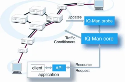
Figure 2.1 depicts an overview of the Operax IQ-Man™ system. Its main components are a core system and probes. The core contains the database used to store resource reservations and topology map and is responsible for handling resource reservations. The Operax IQ-Man™ probe implements topology monitoring. The application interface to Operax IQ-Man™ handles resource reservation requests and replies.
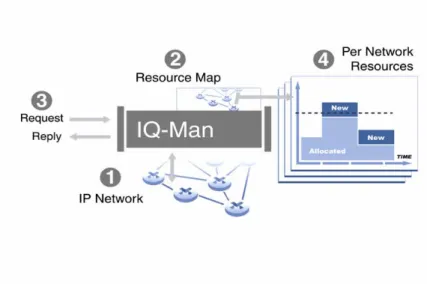
Figure 2.2 shows how IQ-Man™ works. Operax IQ-Man™ connects to the network (1) and builds an up-to-date resource map (2) including routing topology and link resources in a database. This information is used for admission control purposes. As admission requests (3) arrive to the system, the resource map and the allocations (4) are reviewed in order to perform path sensitive evaluation when replying to the requesting application.
Figure 2.2 Description of how IQ-Man™ works
In Operax IQ-Man™, topology awareness is crucial for the path sensitive admission control provided. Topology maps are essential in the process of resource reservation that IQ-Man™ performs.
2.2 Network Simulation and Emulation
Motivation
Network simulators and emulators allow researchers to create arbitrary network topologies and conditions in a reproducible manner that might not be easy to find in real networks [Al97].
When network and protocol interactions are investigated or when new networking tools are verified, network simulators and emulators can be of much help. They allow tests to be carried out in a contained and controlled environment. Thereby, errors are easy to detect and to trace.
Investigations and tests of networking tools often require large networks. Limiting factors for conducting tests in real networks are:
• Cost
o Large networks require a lot of expensive hardware. The cost may not be justifiable.
• Space
o Much hardware requires much physical space. It might not be
possible to fit in all hardware in a test lab.
• Complex setup and configuration
o Managing network devices often require much knowledge from
administrators. Much time is often needed to reconfigure the devices when changing network topology or router functionality between different tests.
All of the above limitations can be reduced by using simulators and emulators. Cost and space limitations can be completely removed as entire networks can be modeled
in a single computer program. Setup and configuration can be made with scripts that are a part of the network topology definition.
There are of course, disadvantages with simulated and emulated networks. The differences between the simulated/emulated networks can cause the results to differ compared to tests performed in a real network. This must always be kept in mind when presenting results from simulations/emulations.
Network Simulators
Network simulators do not carry traffic from one node to another; instead they model traffic and network components internally. The strength of simulation is that it allows researchers to study complex network topologies that might be difficult to create with real networks [Al97].
Network simulators are commonly driven by event queues which create an easy-to-follow line of execution in changes of states and behavior of the network.
An important advantage of simulation is that a simulator is not limited by the speed of real network components, the speed needed can simply be modeled. However, the downside of simulators is coupled to this advantage; they do not interact with real network components or applications. Instead the simulation is isolated from external interference.
Network Emulators
Emulation is a wide concept with a lot of various definitions. In some, network emulators alter real network traffic between physical network nodes in order to model different network configurations [Al97]. Code written for real networks can be used in an emulator and vice versa. This allows testing of code that can be used in real networks and not just testing of concepts as in simulators.
The downside of these types of emulators is that the speed of the emulated network can never be faster than the speed of the physical network components. Another downside – and important difference from simulators – is that complex topologies are difficult to create since they must be created with physical network components. Other definitions describe emulation as a hybrid approach of simulators, emulators as above and live networks [Wh02].
Emulator Definition
The definition of a network emulator used in this thesis is as follows:
The emulated network is an environment with a well defined interface which is used for interaction with the emulated network. The emulator allows applications, protocols or operating systems to interact with it as if it was a network of arbitrary type and size. The interaction can be made quite transparent to the networking tool thus making the tool act is if the interactions are made with a real network.
The emulator may have the whole network topology in a contained space thus it can be run on a single computer. This enables to run the emulation with a greater control than in a real network.
Emulators are not necessarily limited by the speed of physical network components. The speed of network components (e.g. interfaces) or the proceedings of routing protocols can be modeled to any arbitrary value.
The states and behavior are controlled by an event queue. This has many advantages and the foremost is the ability to keep it simple.
2.3 MPLS
MPLS has spawned from early tag switching and label swapping protocols. Ipsilon’s IP Switching, IBM’s Aggregate Route-based IP Switching and last but not least Cisco’s Tag Switching were some of the approaches to provide data forwarding with the use of labels [Ri01].
These protocols had two general purposes; to resolve challenges presented with overlay models like ATM and IP. Secondly, software routers were believed to have great potentials for the future but they needed to be faster as networks grew larger and this could be accomplished by using protocols with faster decision making – i.e. the protocols above.
However, the arrival of hardware routers meant that there was no longer any need for extending the life of software routers since they could not compete with hardware routers in terms of speed. Fortunately, the concept of label switching got new purposes as the demands for traffic engineering and quality of service grew larger. The rapid growth of Internet and thereby the number of routes through it is another reason why there is a demand for the fast tag switching concept.
In 1997 the Internet Engineering Task Force (IETF) formed the MPLS Working Group. In 2001 the first MPLS RFCs were released [Bl02]. MPLS is an approach to forward packets at a high rate of speed. It aims to combine the speed and performance of layer 2 with the scalability and IP-like intelligence of layer 3.
MPLS includes among others the following important features:
• VPNs
• Traffic Engineering, enabling QoS
In traditional IP routing, a packet is forwarded on a hop-by-hop basis in every router it traverses. In the forwarding process, the layer 3 destination address is compared against a routing table in order to find the next hop router. The layer 3 addresses are left untouched by the router in order for the next hop router to be able to perform the same process. This is done independently in every router along the packet’s path thus making the forwarding process through the network to a repetition of time consuming route lookups.
As packets reach the ingress router of an MPLS network, the label edge router (LER), each packet is classified and assigned to a forwarding equivalence class (FEC). This could be compared with the destination address lookup in IP forwarding. However, in MPLS the assignment of a packet to a FEC is done only once – when the packet enters the network.
Different kinds of packets which still are mapped to the same FEC are indistinguishable in the MPLS network. All packets which belong to a particular FEC and which travel from the same node will follow the same path. A route in an MPLS network is called a label switched path (LSP).
FECs provide MPLS with the power of traffic engineering as they can be based on simple matters such as destination prefix of packets or they can be based on more complex factors. Port numbers, source and destination host address or combinations of these are examples of variables that can be taken into consideration for deciding what routes packets are to be forwarded in.
FECs and LSPs are tightly coupled as all packets in a certain FEC will be forwarded along the same LSP. In every forwarding router, called label switching router (LSR), LSPs are identified with labels. An MPLS label has a fixed length of 32 bits and is locally allocated in each LSR.
After the packet has been assigned a label that shows which FEC it belongs to, the packet is forwarded through the MPLS network and no further investigation of the
packet is needed. Each subsequent router uses the label as an index into a table, the label forwarding information base (LFIB), which specifies the next hop along with a new label for the packet. The old label is replaced with the new label and the packet is forwarded to the next hop.
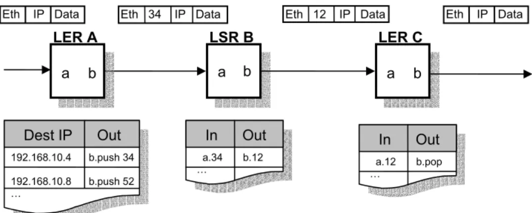
MPLS has sometimes been described as a protocol between layer 2 and layer 3 because the label is inserted into the packet between the layer 2 and layer 3 headers. Figure 2.3 shows an MPLS network of three routers. Ethernet links are used as layer 2 and IP as layer 3. The tables next to each router contain a subset of the forwarding tables (LFIBs). As packets enter LER A, the destination IP is used to map it to a FEC. The label for the FEC is inserted between the Ethernet header and the IP header. The packet is then forwarded out on interface b. In LSR B, the packet’s MPLS label is inspected, swapped with the local out label for the LSP in question and forwarded out on its b interface. When the packet reaches the egress router, LER C, the label is popped and the IP packet is forwarded on.
Fig 2.3 Example of how a packet is classified at the LER A and then forwarded through the MPLS network. The forwarding process through the MPLS network is a simple matter for the LSRs. They only look at the labels and interfaces in order to decide where to forward the packet.
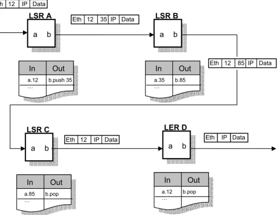
Tunnelling in MPLS networks can be created with label stacking. Label stacking means that a packet carries more than one label. Figure 2.4 shows an example of label stacking in MPLS. A tunnel exists between LSR A and LSR C. When a packet with label 12 arrives at LSR A, it does not swap it with 35 instead it pushes it on top of the label stack. The packet is then forwarded through the network until it reaches LSR C where the label stack is popped and forwarded on. At this point the packet looks exactly as it did when it arrived at LSR A – it has been tunnelled.
LER D inspects the packet and pops the label stack once more thus making the packet into an IP packet. This means that LER B’s interface b is an egress interface and is connected to an IP network.
Eth 34 IP Data LSR B a b LER C a b Dest IP Out 192.168.10.4 b.push 34 192.168.10.8 b.push 52 … In Out a.12 b.pop … Eth IP Data LER A b a
Eth 12 IP Data Eth IP Data
In Out
a.34 b.12 …
Figure 2.4 Example of tunnelling between LSR A and LSR C with label stacking.
Label Distribution
A fundamental concept in MPLS is that two connected LSRs are agreed on the meaning of the labels used to forward packets between them. The MPLS specification does not specify how the labels are distributed [Ro01].
A couple of different approaches has been made to solve this; existing routing protocols, such as the Border Gateway Protocol (BGP) have been extended to piggyback the label information in the routing protocol [Re01].
The IETF has defined a label distribution protocol called the Label Distribution Protocol (LDP) [An01]. In LDP, the LSRs negotiate the labels to be mapped to certain destinations. Simplified, it can be said that LDP maps unicast IP destinations into labels. As in almost all protocols, there are some minor delays in the distribution of the labels.
One of the most important services of MPLS and LDP in particular is the support for constraint based routing (CR). Constraint based routing offers the ability to extend the information used to setup paths beyond what is available for the routing protocol. Constraint based routing supports traffic engineering and can be used to set up LSPs based on explicit route constraints or QoS requirements.
Label distribution protocols that support constraint based routing have been created. The Constraint based Routing Label Distribution Protocol (CR-LDP) specifies an end-to-end setup mechanism of a constraint based routing label switched path (CR-LSP) initiated by the ingress LER [Ja02]. It also specifies mechanisms to support reservation of resources using LDP.
RSVP has also been extended to support piggybacked exchange of labels and is called RSVP-TE [Aw01]. This specification enables the establishing of explicitly routed LSPs using RSVP as the signalling protocol. The major benefit of the protocol is the creation of LSP-tunnels which can be automatically routed away from bottlenecks, congestion and network failures.
LSR A a b In Out a.12 b.push 35 … Eth 12 IP Data LSR B a b In Out a.35 b.85 … LSR C a b In Out a.85 b.pop … Eth 12 35 IP Data LER D a b In Out a.12 b.pop … Eth 12 85 IP Data
2.4 SNMP
In the middle of the 1980s, internets grew rapidly larger. There was no TCP/IP network management standard and when the number of network elements such as bridges and routers grew the administration of them became a task that required a lot of resources.
In the IAB conference in March 1988, the IAB expressed its gratitude to the different working groups of the IETF that currently worked on TCP/IP network management protocols [Ce88]. The IAB described an immediate need for more functionality in those network management protocols.
In order to get a working protocol in short time, two protocols were to be developed in parallel, one very simple that could be defined in short time and another more complex that probably would take longer to define. The idea was that SNMP would serve as the simple short term protocol and a further development of CMIP/CMIS [Wa90] would be the more complex solution. A transition from the simple protocol to the complex one was supposed to occur sometime in the future.
The Simple Network Management Protocol (SNMP) group was formed and was responsible for developing a simple short-term network management standard based on the Simple Gateway Management Protocol (SGMP) [Da87]. In [Ca88], SNMP is defined for the first time. In 1990, the final publication of SNMP version 1 was published [Ca90]. Since then, version 2 [Ca93] and version 3 [Ca02] has been developed.
SNMP is designed to reduce the complexity of network management and minimize the amount of resources required to support it [Se00]. SNMP provides for centralized network management with the flexibility to allow for the management of vendor-specific information.
Management Information Base (MIB)
A MIB is a tree structured database that contains information necessary to the network element [Ro90]. The addressing of nodes is done with assigning every object with an Object ID (OID). Every node in the tree has a node number, value type and the value itself. The number of a node together with the numbers of the nodes leading up to the root of the tree creates the nodes OID.
Figure 2.5 shows a fictitious MIB tree. The figure reveals the content of two of the nodes; 3.3 and 3.3.9. Node 3.3 contains a value of String type with the value of “ABC” while node 3.3.9 is an Integer with the value 1453.
Figure 2.5 An example of a MIB tree.
There are today many different MIBs, some are IETF standards, such as the MIB-II that contains TCP/IP related data and some MIBs are totally vendor specific [Mc91]. What MIBs a device is using is totally up to the vendor and the administrator of the device. Operation Overview 3 1 3 7 4 9 9 OID: 3.3.9 Type: Integer Value: 1453 3 levels OID: 3.3 Type: String Value: “ABC”
Network devices (routers etc.) that are SNMP enabled run a SNMP management agent. These agents can communicate with SNMP management applications and allowing them to fetch or alter information in the network device. The SNMP agent operates on MIBs. SNMP messages are sent asynchronously over the layer 4 protocol UDP.
The SNMP operations are
• GET_REQUEST
o The management application requests an object from an agent
• GET_NEXT_REQUEST
o The management application requests the next object from an agent
• SET_REQUEST
o The management application sets the value of an object within an agent
• GET_RESPONSE
o The returned answer from one of the above requests
• TRAP
o Agents can send a trap when a condition has occurred, such as a change
in state of a device or a device failure
2.5 TELNET
TELNET is a TCP based two-way communication protocol designed in 1980 [Po80]. In 1983 a new version came with some improvements [Po83]. The primary goal was to create a standard for interfacing terminal devices and terminal-oriented processes to each other.
The TELNET protocol is built upon three ideas; the network virtual terminal, the concept of negotiated options and third, a symmetric view of terminals and processes. Together they produce a flexible way of communicating with the possibility of letting the two nodes negotiate how the communication is to be done and what options to use.
There are a number of different options defined in different RFCs. [Re03] always contain an updated list of all RFCs, including all TELNET options.
A TELNET session is created by opening a TCP connection between the two hosts. TELNET communication is simply a way to negotiate options and sending text messages between the hosts. The messages are 8-bit encoded ASCII chars.
The TELNET protocol has no built in encryption of the data sent between the participants of the TELNET session. To avoid malicious users to intercept passwords or other sensitive information, an encryption option for the TELNET protocol has been proposed [Ts00]. TELNET authentication options are also proposed [Ts00-2].
The power of TELNET lies in its simplicity. TELNET applications can exchange information, alter information at each other and also execute programs at the each other. TELNET applications can be designed to let the user get large volumes of information in nicely formatted outputs with just a single command. This is something that many router vendors have utilized. For example it is possible to fetch entire LSP tables with a single command.
3 Goals and Requirements
Although the concept of label switching has been around for many years, MPLS has not been developed for more than a few years. Many MPLS network devices as well as MPLS applications are continuously arising in the market. In addition, many extensions to the MPLS concept are continuously being developed and integrated. Verification and validation of these new devices and applications may have a lot to gain if performed in a contained, controlled environment – i.e. in an emulator.
3.1 Goals
The main goal of this thesis is to design and implement an MPLS emulator that is to provide an MPLS network topology to a network topology gathering tool developed in a separate master’s thesis [Ni03]. The main goal is also to test and verify this tool, called the probe, with the MPLS network emulator.
The secondary goal of this thesis is to design and implement a network topology generator. This is important because the probe must be tested with a large number of different network topologies in order to verify its correctness.
3.2 Emulator Requirements
The requirements of the emulator are:• Transparency
o Communication between the probe and the emulator should be made
transparent via a well defined interface
• Diversity
o Routers must be configurable to behave in the same way as different real router types
• Correctness
o The topology data fetched from the emulator must at all times exactly match the internal topology in the emulator
• Scalability
o The emulator should scale linearly with respect to memory usage and time for data retrieval from all emulated routers as the number of routers increase
• Stability
o Long term testing of the probe requires that the emulator is able to run continuously for a long period of time
• Alteration
o The emulator must be able to alter the topology during a running
emulation. Alterations shall be able to be predefined or be randomly created during the running emulation
• Code standard
o Design and implementation shall follow the guidelines presented at
Operax
Below follows more details on some of the requirements:
Transparency
Communication between the MPLS emulator and the probe must not be on a level too low because of the increasing complexity that brings. Nor should it be too abstract which would result in non-reliable tests of the probe. For example, simply implementing a function in the emulator that returns the entire network topology via an arbitrary struct would not be very realistic. That would not verify the probe in any way except for the probe interface towards IQ-Man™.
Complete transparency to the probe will not be possible in this thesis. The complexity of the emulator would be too high and there will not be enough time to implement it. Thus, the transparency requirement does not require complete transparency. However, data processing in the probe must be performed the same way regardless whether a real or emulated network is used.
Correctness
An emulator with the foremost purpose of delivering a network topology to an application implicitly has the requirement of sending the correct data to the application. Measurements of correctness of the application are likely to be very important. For instance if the user expects to see a predefined alteration pattern in the emulator this must be ensured and therefore the correctness demands of the emulator are of great
importance. Thus the correctness requirement means that the emulator must work as intended – no inconsistencies, no matter how small, are allowed.The emulator shall test and verify the functionality of the network topology awareness tool developed in the master thesis [Ni03].
Scalability
Scalability requirements of the probe have been set to preferably scale linearly with respect to time cost [Ni03]. In order to perform benchmarking of the probe, the emulator should in the worst case scenario have a total data-retrieval time that scales linearly (i.e. O (n)). If the scalability of the emulator is worse than 0 (n), the benchmarking tests of the probe, when used with the emulator, will not prove anything as the tests would only show how the emulator scales.
Stability
Long term stability must be ensured in order to verify the probes functionality and stability. Possible reason for crashing such as memory leaks must be eliminated.
3.3 Topology Generator Requirements
The requirements of the topology generator are:
• Configuration
o The topology generator must be configurable to create network
topologies of varying sizes
• Random behaviour
o It must be able to create the networks in a random manner, but also be able to reproduce networks for future re-tests
• Compatibility
o It must create network topologies that can be used in the MPLS
emulator
3.4 Delimitations
An emulator that emulates an MPLS network in full detail of every aspect is a goal that could never be fulfilled. Delimitations must be made to be able to produce a result in feasible time.
Multiple domain networks are not to be modelled. The probe is only intended to be used on a per domain basis and thus the emulator needs only describe one domain. The emulated routers will not perform all the tasks of a real MPLS router (label distribution or forward any traffic). The goal to provide the probe with the requested data (the label switched paths in the network) does not imply how the LSPs are set up, just that they exist.
4 Related Work
A Linux™ based MPLS Emulator (LiME) is an MPLS emulator that can be used as a test environment for testing control protocol implementations [Ab02]. LiME supports LDP and is also able to forward traffic between its emulated nodes using a kernel space MPLS stack. It is capable of running code developed for real network devices and may also communicate via a network interface with real MPLS devices.
LiME is useful when studying deployment effects of different traffic engineering algorithms within MPLS networks. However, it does not cope with large topologies. The design of LiME does not allow large topologies without redesigning it to a distributed system.
Another MPLS emulator is the commercial NetTest MPLS InterEMULATOR™ [In01]. InterEMULATOR is intended for testing of new protocols, network devices and to study algorithm behavior. It also allows active insertion of errors in packets in order to
study error detection and correction. The emulator is, according to the developers, highly developed and allows validation of performance, functionality and interoperability of network devices and algorithms.
Like LiME, it is intended to be connected with real MPLS hardware. One big difference from LiME is that InterEMULATOR supports emulation of up to 300 LSRs on a single workstation. It supports LDP, CR-LDP and RSVP-TE as label distribution protocols and BGP-4, OSPF(TE) and IS-IS(TE) as routing protocols.
The emulators above aims to validate MPLS related algorithms or real MPLS network devices. The emulator in this thesis is in a way much smaller as it does not implement any label distribution protocol, run code intended for real devices or communicate with such. The emulator in this thesis aims at containing an MPLS network topology, being able to dynamically alter the topology during run-time and to provide a well defined data information retrieval interface in the emulated routers. Through the interface, topology information is to be fetched.
Some of the design and development of the MPLS emulator in this thesis has also been influenced by how the Operax IQ-Man™ MPLS Probe is designed.
5 Design
5.1 MPLS Emulator
5.1.1 Overview
The MPLS Emulator is designed to run together with the Operax IQ-Man™ MPLS Probe implemented by Per Runemo and Martin Nilsson [Ni03]. The probe provides the Operax IQ-Man™ Core system with MPLS network topology information.
The main components of the emulator are a set of router objects, a scheduler object and a communication interface. These objects are explained more in detail below.
Features
The emulator is capable of modelling an arbitrary number of router types with different configurations. This is solved with the use of plug-ins. Every router type with a specific configuration can be imitated by implementing a plug-in for that router. This way, new router types can easily be added to the emulator.
Network fluctuations frequently occur in real networks and are important to model. Therefore, the emulator has a scheduler object. It schedules events such as dropping routers and LSPs. An event handler makes sure that the modelled network is altered according to the events.
Communication with the routers can be done in two ways; SNMP and TELNET. (Actually pseudo SNMP and pseudo TELNET implemented with library function calls; see section 5.1.3 for more details). The communication is done via a common interface in the emulator from where SNMP and TELNET sessions can be opened.
Initialization
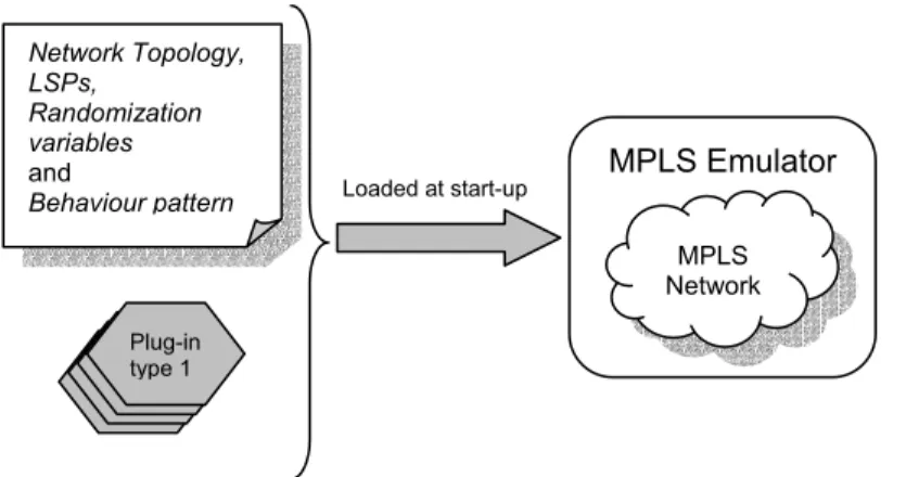
Figure 5.1 shows how the emulator is loaded with a number of different settings at start-up.
At initialization, the emulator’s configuration file is read. The network topology contains information about the routers, their interfaces and how they are connected. The LSPs defines all label switched paths through the network. The randomization variables define the optional random generation of events (see section 5.1.5). The behaviour pattern defines prescheduled events that are to occur in the emulator.
Fig 5.1 The emulator is loaded with network topology, initialization variables, behaviour pattern, and the different router type plug-ins needed.
When the configuration file is read, the topology objects, prescheduled events and the scheduler are created. The scheduler creates the event handler and is thereafter started.
After initialization, two things can occur; communication with the emulator can be requested by the probe or an event may be processed.
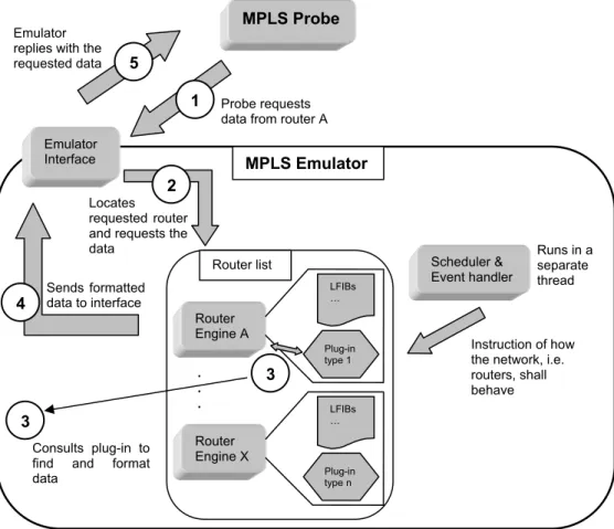
Course of actions
Figure 5.2 shows how a SNMP or TELNET request is handled in the emulator. The probe initiates communication by requesting some data from router A via the emulator interface (1). The interface receives the request from the probe and maps it to a router object. The router object gets a request from the interface regarding the requested data (2). The data might depend of the router type and if so, the router engine uses the router type plug-in to get the right data formatted in the correct way (3). The LFIB table in the router contains information about the LSPs in this router. If the request is regarding LSPs, that table will be used by the plug-in to get the data. The router engine returns the data to the interface (4). The interface replies to the probe with the requested data (5).
The third step applies for TELNET requests. In the case of SNMP requests, router specific information has in advance been added to the router’s MIB tree (see section 5.1.4 for more details).
Network Topology, LSPs,
Randomization variables
and
Behaviour pattern Loaded at start-up
MPLS Emulator MPLS Network Plug-in type 1
Figure 5.2 Overview of how the emulator is designed.
5.1.2 Emulator Library
The emulator is designed as a library and is executed together with the probe. This way the probe and emulator communicates via library functions. The library functions constitute an application programming interface (API).
The advantage with this solution is that the communication is kept on a level not too low as required in section 3.2.
Another advantage with this solution is that it is very time efficient. The time needed to send data via library functions compared to retrieving it via a network link is almost zero.
Another solution is discussed in section 10. It involves communication via a real network interface. That solution would be to prefer but the implementation of it would not be feasible in this thesis due to the complexity it brings and the limited time for this thesis.
The MPLS emulator is compiled as a shared, dynamically linked library. The emulator’s API consists of an initialization function, pseudo SNMP and TELNET functions (see section 5.1.3), and a function to halt the emulator when ending the emulation.
5.1.3 Emulator Interface
The library API allows the probe to perform synchronous SNMP and asynchronous TELNET queries. Sessions are set up in a similar way to how sessions are set up with real routers.
The reason for why the emulator supports those two methods is because the probe does not use any other method to fetch the required information.
Emulator replies with the requested data
Locates requested router and requests the data
Emulator
Interface MPLS Emulator
Instruction of how the network, i.e. routers, shall behave . . . Router Engine X Plug-in type n LFIBs … … Router Engine A Plug-in type 1 LFIBs … Router list MPLS Probe Probe requests data from router A
1
2
3
Consults plug-in to find and format data 3 Sends formatted data to interface 4 5 Runs in a separate thread Scheduler & Event handler
The probe could have used other methods such as snooping on the routing or label distribution protocol to retrieve the necessary information. In such a case, the emulator could have modelled this by implementing the required routing protocol. The scheduler and event mechanism would serve as the coordinator in the distribution of routing messages and the router engines would be responsible for receiving, processing and creating these messages.
SNMP
UCD-SNMP is the one the most widely used packages for SNMP communication [US03]. It is also what the probe uses for SNMP communication with real routers. Therefore, the emulator provides functions in its API that imitate the library functions of UCD-SNMP and the probe is instructed to use those SNMP functions instead of the UCD-SNMP functions when it is run against an emulated network.
By providing functions in the API that to the probe look and behave the same as the functions in UCD-SNMP, the probe is made to believe that it interacts with a real network. This assures that transparency will be high between the probe and the emulator but not unnecessary complicated.
The imitated functions correspond to opening an SNMP session, making synchronous queries and closing an SNMP session.
TELNET
The TELNET approach is similar. The probe uses its own small TELNET API when run against a real network. The emulator provides functions that imitate those functions. The probe is instructed to use the emulator’s TELNET API instead of its own when run against an emulated network.
The TELNET API consists of four library functions. They allow opening a telnet session, sending queries to the emulator, receiving replies from the emulator and closing the session. Compared with how a real TELNET session is used [Po83], this creates a high level of transparency to the probe.
The use of library functions has one downside; all communication between the probe and the routers are serial. When the probe interacts with routers in a real network some of the communication can be done in parallel.
However, there are two reasons why this is not a problem; first, the probe is only parallel to a certain extent i.e. it cannot be truly parallel if the number of routers are too high. Instead several routers will be polled in a serial manner. Secondly, tests (see section 7.1.3) of the emulator shows that topologies with a large number of routers does not slow down the communication process to much for the emulation to finish in acceptable time.
5.1.4 Router Engine
The emulator contains a set of router objects. The purpose of these objects is not to forward packets or to create and manage LSPs with some protocol such as LDP. Instead the purpose of the router objects is to contain information important to the probe.
The information needed by the probe is information about the routers (e.g. type of routers), about the interfaces (how many they are, their type and speed, if they are MPLS interfaces etc.) and last but definitely not least information about LSPs through the emulated network.
Router types
A network emulator would not be very useful if it was only able to emulate one type of router. One solution to this would be to hard code support for a number of router types
into the emulator directly. This would result in a very large amount of code and it would require recompilation of the emulator every time a new router type is needed. The emulator is instead designed to dynamically load the characteristics of the modelled router. Along with the topology definition in the configuration file, each router is assigned a router type. The type is associated to a shared library that is loaded dynamically at initialization. This is called the plug-in model.
For the router to be able to cope with SNMP requests it has a MIB tree. The tree always contains a subset of the standard MIB MIB-II. This MIB does not contain any MPLS specific information.
The plug-ins are responsible for two things. One, they provide functions that add router type specific MIB objects to the router’s MIB tree. For example, if a specific router type delivers certain MPLS information via SNMP, the plug-in for that router type adds the information to router’s MIB tree.
Second, they provide functions that are responsible for receiving and processing TELNET requests. TELNET requests from the probe are directed to the router’s plug-in. There, the plug-in does all the processing of the request. The reason for this approach is quite simple; virtually all router vendors implement their own TELNET interface and they can differ a lot from each other. It is therefore not possible to implement some sort of standard TELNET processing in the router objects.
Every plug-in is implemented according to a template. The template defines the methods for creating router specific MIB trees. It also defines methods for the TELNET queries. Methods that perform unspecified actions, such as important initializations, are also defined.
5.1.5 Scheduler and Event Handler
The emulator uses a scheduler and an event handler that can alter the characteristics of the network. It runs in a separate thread in order not to interrupt the emulator from doing what it currently does. To assure that the scheduler does not alter the topology at critical moments (e.g. when a router is being polled), a mutex lock is used.
The scheduler queues events sorted after their time stamp, putting the next event to occur in the head of the queue. It then checks the head of the queue to see when the event is to occur and waits for that amount of time. When an event is to be processed, the scheduler passes the event on to the event handler which processes the event and possibly adds new events to the scheduler as a result of the processed event. The scheduler then waits until the next event is to occur.
5.1.6 Events
There are three types of events; events that make a LSP go down or up, events that make a router go up or down and third, events that generate random instances of the previous events. Fluctuations are common in real networks and the meaning of these events is to make the network fluctuate in order to emulate that behaviour.
When a router that is a node in an LSP goes down, the event handling mechanism also makes sure that the LSP is removed from the network. The effect is almost instant; the delay in the down tearing process of the LSP is only a matter of milliseconds. The process is similar (but backwards) when that router goes up again. In a real network where LDP may be used, the LSP would be broken for a longer period of time. The probe would detect a larger number of topology alterations due to the delays until the network reaches a stable state. This difference reduces the level of reality in the emulator and could be improved in future development. However, the higher stress to the probe that many alterations bring can be modelled by generating more fluctuation events.
Randomization
A feature in the scheduling and event handling mechanism is that it can create random events. Random events are created every X time interval and cause some routers to go down for a period of time.
The randomization process is configurable and gives the user the ability to control the time interval and an instability factor for all routers or set it individually for certain routers. There are also other configurable randomization options, see section 6.2. The feature of random events has two advantages: the network becomes more real in the sense that there is no regular pattern in the disabling of routers as there would be when humans disable routers manually in testing purposes. Secondly, a long term test of the probe would reveal any faults arising from the inability to cope with unstable networks.
5.1.7 SNMP Engine
The SNMP engine handles the GET_REQUESTs and the more complex GET_NEXT_REQUESTs to a router. It also produces the GET_RESPONSEs to send back to the probe. It does not handle SET_REQUESTs or create TRAPs as there is no need for that in the emulator.
SNMP operations are closely related to a router’s MIB tree. The structure of the MIB trees must always follow a certain set of rules to qualify as a MIB tree. The SNMP engine has functions to ensure that all insertions and removal of objects in the MIB are done a correct way.
The SNMP engine is used by all routers when building, rebuilding and destroying their MIB trees (caused by topology changes made by the scheduler). Since all router objects use it, it has been designed to be static.
5.2 Topology Generator, Topgen
5.2.1 Overview
Large networks are often needed when testing network tools. A program named Topgen has therefore been implemented in this thesis. Topgen generates random network topologies and calculates and creates shortest path LSPs between all edge routers.
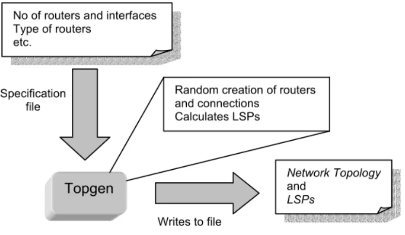
Figure 5.4 shows how Topgen is used; a configuration file that defines how many LERs and LSRs, maximum and minimum number of interfaces allowed and what type of routers that are to be generated is read by Topgen. Topgen does the necessary calculations and randomizations to create a complete network topology and all LSPs through it. The topology is then written to a file.
Figure 5.4 Topgen creates a complete network topology and LSPs from a predefined set of demands.
5.2.2 Creation model
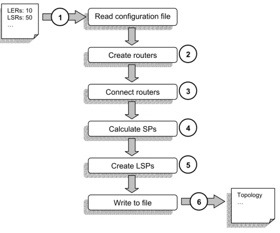
Figure 5.5 describes the course of events when Topgen creates a network.
Step 1
The first step is the simple matter of reading the configuration file. This file contains the following information (and a bit more):
• Topology output file name
• Number of LERs wanted
• Number of LSRs wanted
• Number of shared segments wanted and maximum number of routers in a
shared segment
• A minimum and maximum number of interfaces on the routers
• Router types to be created (specified by strings such as “Cisco_2651”)
• A ratio of how many routers of each type that are to be created
• A random seed
The router type ratio means that the user can decide how many routers of each type the network should contain. For instance the user may want a network with 20% of the routers to be of type A, 40% of type B and 40% to be of type C.
Step 2
The information from the configuration file is used to create the LERs, LSRs and their interfaces. The number of LERs and LSRs are fixed but the number of interfaces for each router is randomly selected. The number of interfaces for a router is selected by generating a random number in the interval of maximum and minimum allowed routers.
Every router gets a router type assigned to it. If a ratio has been specified for each router type then this ratio is used when assigning the routers their types. If not, a rectangular distribution is used when assigning router types meaning there statistically will be equally many of all types.
Specification file
Topgen
No of routers and interfaces Type of routers
etc.
Network Topology
and
LSPs
Random creation of routers and connections
Calculates LSPs
Fig 5.5 Overview of the steps performed in creating a network topology with Topgen.
Step 3
The third step is the largest one. In this step, all routers are connected to each other and assigned IP addresses. All router and interface selections are done at random. First it creates all the shared segments by selecting those routers that are to be in the shared segments and connects them. All of the LERs’ interfaces, except for one on each LER, are then connected to some of the LSRs. The unconnected LER interfaces will be used as the ingress/egress interfaces.
The LSRs are then connected to each other on all their unconnected interfaces. This may create several connections between the same two pair of LSRs which is very likely to occur in real networks.
Finally, every subnet that has been created by connecting interfaces to each other is given a subnet IP prefix. From this prefix the interfaces are then given their IP addresses.
Step 4
The topology is now finished and the LSPs are to be created. Dijkstra’s shortest path (SP) algorithm [Co90] is used to determine the shortest paths between all LERs.
Step 5
The information from step 4 is used to create LSPs from every LER to every other LER. More precisely, it creates LSPs from the subnet of a LER’s ingress interface to the egress interface of every other LER.
Step 6
The last step writes all the generated information to a file with the requested file name.
LERs: 10 LSRs: 50
… Read configuration file
Create routers Connect routers Calculate SPs Create LSPs Write to file Topology … 1 2 3 4 5 6
6 Implementation
This section explains how the work has been performed and also some detail decisions made in the implementation.
The implementation is written in C. The code follows the ANSI C standard and the Operax AB coding standards. The emulator implementation has been written on Red Hat Linux 7.3 operating system using the Gnu Compiler Collection (gcc) version 2.96.
Thread Support
The emulator is fully thread safe meaning that the probe may query the emulated network in parallel threads.
Topology Freeze
In the implementation of the emulator, support has been added to freeze the state of the network topology for a period of time. This feature has been added in order to verify the correctness of the probe. The freezing is done with custom made events that occur every X seconds. The freezing of the topology lasts for Y seconds and just before it is unfrozen it is compared with the topology fetched by the probe.
All configuration of the freezing (freeze interval, freeze length etc.) is done via the configuration file.
MIBs supported
The MIBs supported in the implementation are subsets of the MIB-II [Mc91] and the MPLS LSR MIB [Sr03]. The MIB-II support is built in to the router object while the MPLS LSR MIB is built in to the implemented router type plug-in (see below).
Plug-ins
The creation of plug-ins is designed to be an easy task. To help the implementation of new plug-ins, a template is supplied. The template is a C h-file that describes the functions that need to be implemented and what they must do.
In the implementation done in this thesis, one router type plug-in was created. It imitates the behaviour of the Cisco models 2651 and 3620. The MPLS LSR MIB support is only a subset of the defined content of that MIB. The parts not needed for network topology extraction has not been implemented.
6.1 Dependency Graph
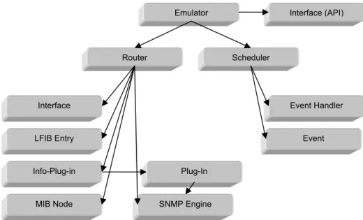
Figure 6.1 shows the modules and objects and their dependencies.
Fig 6.1 The objects and modules. The arrows indicate how objects and modules are used.
Event Event Handler Interface LFIB Entry Plug-In Router Scheduler
Emulator Interface (API)
SNMP Engine MIB Node
The figure does not show how many objects instances that are owned by any object, just how they are owned.
The figure shows that the emulator object contains router objects, a scheduler and an Interface.
A router object owns interfaces, LFIBs, an Info-Plug-in, and a MIB Node. The MIB Node is the root of the router’s MIB tree which contains subsequent MIB Nodes. The Info-Plug-in contains the router type plug-in. Both the router object and its plug-in uses the functions in the SNMP Engine.
The Scheduler object contains a list of events that are dispatched to be processed at the Event Handler. The Scheduler and Event Handler runs in a separate thread.
6.2 Configuration
Configuration of the emulator can be divided into two parts; setting up the network topology and setting up the emulator’s internal functionality.
6.2.1 Network Topology Configuration
The network topology used for the emulation is read from a file. The file contains a set of routers including their interfaces. Each router may also have a set of neighbour routers. This information creates the network topology.
The file is built with hierarchical clauses; the router clause is the topmost clause and contains the config, iface and the neighbour clause.
The config clause holds information such as the router’s IP-address, a textual description of the router and TELNET and SNMP passwords for the router. It also contains what type of router it shall imitate and whether or not SNMP and TELNET access is allowed during emulation.
The iface clause holds information about an interface on the router. It contains the interface’s IP-address, type, speed and textual name. It also describes whether or not the interface is an MPLS interface.
The neighbour clause contains a local interface name and the IP-address of the neighbouring router. It also contains a cost for the link.
The information above creates the network topology but not any LSPs. The lsp clause describes a label switched path and contains a destination prefix and several router
clauses (not the same clause as described above regarding the network topology). The router clause contains the IP-address of a router that is a node in the LSP. It also describes what interfaces and labels that the router shall use for this LSP as well as the IP-address of the next hop interface (the interface on the next hop router in the LSP).
6.2.2 Emulator Configuration
There are a number of internal settings in the emulator as well.
The clause emu_log_level sets the level of logging. There are five levels and each level adds additional information; level 0 means that no logging is done at all, level 1 means that only errors are reported, level 2 adds warnings in addition to errors, level 5 adds informational reports and level 6 adds debugging information.
The emu_log_file clause specifies where logging is to be written. If this clause is missing from the configuration file, logging will be done to screen.
The fluct clause defines either a router or LSP along with a list of events. The events are either ups or downs on a time offset from the starting time of the emulator. If a fluct
clause contains the field lsp_id then the purpose of the clause is to make an LSP go up or down. lsp_id refers to the value in the id field of the lsp clause. If the fluct clause instead of lsp_id contains router_addr then the clause is intended to make a router go up and down.
The random_settings clause holds the necessary fields for generating random events.
It contains the following fields; use_random which defines whether or not to use
random events, a random seed named rndm_seed and rndm_calc_interval which is a
timer that describes how often random events are to be generated.
The net_settings clause under random_settings defines how unstable all routers are. The net_risc field specifies how many percent, on the average, of the routers that goes down (and eventually up) every rndm_calc_interval.
The id clause under the random_settings clause defines similar variables as
net_settings but for specific routers.
The freeze_top under the random_settings clause is only used when the topology needs to be frozen. It specifies the freeze_interval, freeze_length. It also specifies log-on variables to be used when comparing the topology with the topology in the IQ-Man™ database.
7 Testing
7.1 Test Cases
7.1.1 Correctness of the Emulator without Fluctuations Description
The test case is created to verify that the emulator provides the probe with the correct image of the emulated network topology. The information gathered during these tests is if the emulator provides the correct and requested information.
Environment and start conditions
The emulator is executed with the settings listed in appendix A.1. The probe is executed with the settings in appendix A.3. The test will be run on the host in appendix A.6 and the number of routers in the topology will be varied to verify that the size or configuration of the topology has no impact on the correctness.
Actions and expected results
The network topologies to test with are generated with Topgen. Several networks are generated and inserted into the emulator. The topology that the probe retrieves is compared with the topology given to the emulator. The result should be that there are no differences in the two topologies.
Observations
Networks generated by Topgen were inserted into the emulator. The numbers of routers in the different networks were 20, 30, 40, 50, 60, 70, 80, 100, 150 and 200. Two fifths of the routers were LERs. This was to ensure that the number of LSPs through the network was significantly high. For instance, the network of 200 routers had 6320 LSPs in total.
A program developed for testing purposes verified that there were no inconsistencies between the network topologies in the emulator and the network topologies retrieved by the probe. The correctness of the emulator when no fluctuations occurred was thereby verified.
7.1.2 Correctness of the Emulator with Fluctuations Description
The test is designed to verify that alterations of the network topology are reflected correctly in the data provided to the probe. The information gathered in these tests is if the emulator provides the correct and up-to-date topology information.
Environment and start conditions
The emulator is executed with the settings listed in appendix A.2. The probe is executed with the settings in appendix A.4. The test will be run on the host in appendix A.6 and the number of routers in the topology will be varied to verify that the size or configuration of the topology has no impact on the correctness.
Actions and expected results
The networks of 20-100 routers used for testing the correctness without fluctuations are extended with fluctuation settings.
Every X seconds, the topology in the emulator is frozen meaning that no changes are allowed. The frozen state is maintained for a time period long enough to assure that the probe has fetched the entire topology and sent it to IQ-Man™ Core. Just before the emulator goes out of the frozen state, it retrieves the topology from the IQ-Man™ database and compares it with the emulator’s internal topology. The result should be that there are no differences in any pair of topologies.
Every Y seconds, new network fluctuations are calculated. All tests are performed with a network fluctuation of 50%, which means that every time network fluctuations are generated 50% of all routers goes down.
The topology freeze intervals were varied slightly as the networks grew larger. This was made to ensure that IQ-Man™ Core had performed all of its calculations before the topology was retrieved for comparison. It also meant that the interval for generating network fluctuations was altered to ensure a high variation in the network topology between any two comparisons.
Observations
In each test, the emulator’s internal topology was frozen 20 times. After each freeze a comparison of the internal topology was made with the topology in the IQ-Man™ database. Every comparison made showed that the topologies were identical. It can therefore be concluded that the emulator provides the correct data of the network topology when fluctuations occur.
7.1.3 Scalability of the Emulator Description
The test case is designed to show how the emulator scales as the number of routers increase. The information gathered here is the average time needed for the probe to perform one fetch iteration and the amount of memory used by the probe and emulator. The fetch iteration collects all data needed by the probe.
Environment and start conditions
The emulator is executed with the settings listed in appendix A.1. The probe is executed with the settings in appendix A.3 and A.5 to illustrate differences in performance between multithreaded and unthreaded execution. The emulator will be run on the host in appendix A.6.
Actions and expected results
The time to perform fetch iterations is very much dependant of the amount of data to retrieve. As the number of routers increase, the number of LSPs through the network grows faster. By increasing the number of edge routers by a factor 2, the number of routes does not double. Instead, the increase in the number of LSPs is almost square. The Topgen program creates two LSPs between all edge routers. The following example illustrates why this grows almost by square: Suppose that the number of edge routers is 5. The number of LSPs is then 5 x 4 = 20. If the number of edge routers instead is 10 then number of LSPs will be 10 x 9 = 90. 20 edge routers will give 20 x 19 = 380 LSPs. The growth is clearly not linear, instead it is O (N x (N-1)) = O (N2 – N) = O (N2).
Therefore, if only the edge routers were to be polled then the scaling is expected to be O (N2). However the scaling should be better since not all new core routers (3/4 of the routers are core routers) are a part of the new LSPs and therefore does not increase their amounts of data as the edge routers do. There is no way to mathematically prove what the scaling should be in general since that depends on the topology and how LSPs are set up through the network.
Observations
30 poll iterations in every network were made and the average time needed by the probe to poll every router is shown in table 7.1 (multithreaded execution) and 7.2 (unthreaded execution).
In multithreaded mode the execution time is higher due to the overhead caused by the large amount of context switching. The standard deviation is also higher in multithreaded mode because of the way the thread scheduling is performed. In some executions, the scheduling is “smooth” in the sense that few threads that are locked by mutex locks are given the opportunity to run while in other executions many locked threads are set in run mode with the result that all they do is to wait for the lock to be released. Number of threads 0 20 30 40 50 60 70 80 90 100 Number of routers 0 20 30 40 50 60 70 80 90 100 Average [s] 0,000 0,087 0,231 0,300 0,546 1,093 1,634 2,183 3,132 3,750 Std. Deviation 0,000 0,062 0,185 0,221 0,338 0,534 0,735 0,814 1,146 1,213
Table 7.1 Total poll times on the average and the standard deviation when the probe is executed in multithreaded mode. Number of routers 0 20 30 40 50 60 70 80 90 100 Average [s] 0,000 0,045 0,140 0,168 0,321 0,464 0,697 0,863 1,192 1,759 Std. Deviation 0,000 0,000 0,000 0,001 0,002 0,003 0,006 0,005 0,005 0,010
Table 7.2 Total poll times on the average and the standard deviation when the probe is executed in unthreaded mode.
Figure 7.1 shows the values from table 7.1 in a graph. Figure 7.2 shows the memory usage for the same executions. Figure 7.3 shows the values from table 7.2 in a graph. The scaling in both time and memory seems to be slightly better than expected for both multithreaded and unthreaded.
0 0,5 1 1,5 2 2,5 3 3,5 4 0 10 20 30 40 50 60 70 80 90 100
Num ber of routers
T o ta l p o ll ti me [s ]
Fig 7.1 The time needed to poll all routers in multithreaded mode.
0 2 4 6 8 10 12 14 16 18 0 10 20 30 40 50 60 70 80 90 100
Num ber of routers
M em o ry u sag e [M B ]
0,0 0,2 0,4 0,6 0,8 1,0 1,2 1,4 1,6 1,8 2,0 0 10 20 30 40 50 60 70 80 90 100
Num ber of routers
T o ta l p o ll ti me [s ]
Fig 7.3 The time needed to poll all routers in unthreaded mode.
7.1.4 Stability of the Emulator Description
This test is designed to verify that the emulator does not crash or leak memory that can lead to a crash.
Environment and start conditions
The emulator is executed with the settings listed in appendix A.1. The probe is executed with the settings in appendix A.3. The test will be run on the host in appendix A.6.
Actions and expected results
The same networks with 20, 50 and 80 routers as above are used for this test.
Each test is run for approximately 24 hours. Memory usage is recorded when the program has reached a stable state. After 24 hours the program is checked to still be running and checked for memory usage. The memory usage should be the same.
Observations
No memory leaks in the emulator were detected during the long term tests. The emulator never crashed during the tests. The stability requirement is thereby considered to be fulfilled.
8 Results
In this section, the results are discussed and compared with the requirements from section 3.
8.1 Requirements
This section shows that all requirements are fulfilled.
8.1.1 Emulator Transparency
The requirement stated that the interface must not be on a level too low or too high. Therefore transparency for the probe is provided on an API level.