Fusion of Force-Torque Sensors, Inertial Measurements
Units and Proprioception for a Humanoid
Kinematics-Dynamics Observation
Mehdi Benallegue, Alexis Mifsud, Florent Lamiraux
To cite this version:
Mehdi Benallegue, Alexis Mifsud, Florent Lamiraux. Fusion of Force-Torque Sensors, Inertial
Measurements Units and Proprioception for a Humanoid Kinematics-Dynamics Observation.
2015 IEEE-RAS International Conference on Humanoid Robots, Nov 2015, Seoul, South Korea.
<
hal-01202155
>
HAL Id: hal-01202155
https://hal.archives-ouvertes.fr/hal-01202155
Submitted on 18 Sep 2015
HAL
is a multi-disciplinary open access
archive for the deposit and dissemination of
sci-entific research documents, whether they are
pub-lished or not.
The documents may come from
teaching and research institutions in France or
abroad, or from public or private research centers.
L’archive ouverte pluridisciplinaire
HAL
, est
destin´
ee au d´
epˆ
ot et `
a la diffusion de documents
scientifiques de niveau recherche, publi´
es ou non,
´
emanant des ´
etablissements d’enseignement et de
recherche fran¸
cais ou ´
etrangers, des laboratoires
publics ou priv´
es.
Fusion of Force-Torque Sensors, Inertial Measurements Units and
Proprioception for a Humanoid Kinematics-Dynamics Observation
Mehdi Benallegue
1,2, Alexis Mifsud
1,2and Florent Lamiraux
1,2Abstract— We present a scheme where the measurements obtained through inertial measurement units (IMU), contact-force sensors and porprioception (joint encoders) are merged in order to observe humanoid unactuated floating-base dynamics. The sensor data fusion is implemented using an Extended Kalman Filter. The prediction part is constituted by viscoelastic contacts assumption and a model expressing at the origin the full body dynamics. The correction is achieved using embedded IMU and force sensor. Simulation and experimentation on HRP-2 robot show a state observation with improves inter-sensor consistency but also increased reconstruction accuracy.
I. PROBLEM STATEMENT
The robot unactuated dynamics and its balance in par-ticular depend only on external forces, mostly reduced to two categories: contact forces and gravity [1]. On one hand contact wrenches can be measured with embedded robot force-torque sensors. On the other hand, we exploit usually the forward kinematics and proprioceptive sensors (joint encoders) to predict the robot weight. This prediction is sometimes corrected using other sensors such as Inertial Measurements Units (IMU) [2], [3]. This correction is specif-ically important in the presence of uncertain environments or compliant parts in the robot.
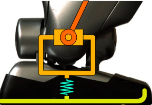
A good example of a robot that requires a fine reconstruc-tion of the floating base kinematics is HRP-2. This humanoid robot has a flexible part that lies between the ankle and the foot. This flexibility is designed to protect the force-torque sensors and the actuators from foot impacts with the environment [4] (see Fig.1).
HRP-2 is already capable of balanced walking with compensating the flexibility deformation using a stabilizer
module. This module uses contact force sensors and has a model of the elasticity of the flexible bush in order to track a given reference contact wrench [5], [6]. Force measurements can also be used to reconstruct the inertial parameters of a humanoid robot [7] including HRP2-foot dynamics [8].
On the other hand, other woks were able to show that it is possible to reconstruct accurately the kinematics of a robot using only IMU measurements [3]. Indeed, inertial measure-ment units provide valuable information about not only the orientation of the robot, but also about the angular velocity and body accelerations in the inertial reference frame. When
*This work is supported by the project ERC Advanced Grant 340050 Actanthrope
*This work was partially funded by the French Romeo–2 project Mehdi Benallegue (mehdi@benallegue.com), Alexis Mifsud (alexis.mifsud@gmail.com) and Florent Lamiraux (florent@laas.fr) are with:
1CNRS, LAAS, 7 avenue du colonel Roche, F-31400 Toulouse, France 2Univ de Toulouse, LAAS, F-31400 Toulouse, France
Fig. 1. The foot of HRP-2. Between the ankle joint and the sole of the robot, there is a flexible rubber bush.
coupled with proprioceptive sensors that provide the position of contact with the environment, the 6D floating base kine-matics becomes fully observable [2]. Furthermore, we have shown recently that this estimation is reliable enough to drive a closed-loop stabilization of the flexibility for a humanoid robot like HRP-2 [9]. In another work, we have shown that the combination of IMU signals with viscoelastic model of the flexibility and the full body dynamical system enables to estimate contact forces and moments without any need of force sensor [10].
Accordingly, we see that IMUs and force sensors pro-vide complementary yet redundant measurements to record contact wrenches and floating base dynamics. However, in order to make the link between the kinematics and dynamics, a dynamical model of unactuated degrees of freedom and contact wrenches has to be built.
In the presence of a force and torque applied on the foot the compliant part is subject to deformation. We can model the flexibility force response to deformation as a rotational and translational spring-damper. By doing so, we link torque/forces to kinematic deviation. On the other hand contact forces drive the floating-base kinematics and gravitational effects on the robot. Reciprocally, we have to take into account that a humanoid robot is not a rigid body. Actuated gesticulation lead to variations of angular momenta and center of mass position, which modifies contact forces and torques and therefore influences partially the flexibility deformation. If we consider all these relations between contact forces, weight, gesticulation, and flexibility deformation we obtain a dynamical system that may predict robot kinetics and even balance.
This model requires all the embedded sensors available on the robot to correct the prediction in real-time. However, to our best knowledge few works merged measurements
from IMUs, proprioception and force sensors of a humanoid robot in a single state estimator that considers full body dynamical model, especially in the context of compliant limbs or surfaces. This paper addresses this issue and shows a simple design using extended Kalman filtering.
In Section II we describe the model of elasticity and its dynamics. In Section III, we show the model of sensors and describe the suggested state observer. SectionIVshows simulations and real experiments and estimation results. Finally, Section V, concludes the paper with a discussion on the results and related works.
II. FLEXIBILITY DYNAMICAL MODEL
A. Flexibility as a 6D transformation
HRP-2 is 30+6 DoF stiffly position-controlled robot. The position, velocity and acceleration of a link is perfectly known in the robot root reference frame and only depends on the 30 dimensional joint positions, velocities and accel-erations. Indeed, these values are not only measured with proprioceptive sensors such as joint encoders, but these variables are actuated to track references provided by full body controllers. Therefore, the availability of link positions is valid for all HRP-2 joints except for the soles, because they lie behind the flexibility which has unkown state. In our next developments, we will ignore this fact, and neglect the mass contribution of the soles.
The controller of HRP-2 considers that the position, the velocity and acceleration of the root reference frame is perfectly known in another reference frame that takes into ac-count the unactuated floating-base kinematics and describes the robot configuration in 36 dimension. All the controllers of the robot are written in this reference frame, that we call “control frame” and we denoteC. Robot controllers assume that C is the world frame, but this assumption is wrong. in reality, the flexibility deformation creates a discrepancy between the control frameC and the actual world reference frameW. The transformation between C andW is a right-handed rigid transformation that can be represented by a homogeneous transformation matrix denotedWMC.
The flexibility is considered compliant on all the 6D. Thus, there is a bijection between the flexibility deformations and possible values of WMC. We prefer then to use WMC to represent any state of the flexibility, instead of representing the 6 DoF deformation at a joint level (see Figure 2). The advantages of this representation are multiple. First it enables to represent the flexibility of any number of contacts, and to stay consistent even if this number is modified. Second, it does not interfere with the controllers of the robot that work inC. Third, it enables to easily compute in W the position of a body that is described by the homogeneous matrixCMi
inC and can be written as
WM
i=WMCCMi. (1)
This flexibility configuration, being an element of SE(3), defines a translation represented by tC ∈R3 and a rotation
in SO(3) represented by a rotation matrix RC ∈R3×3. We
choose to include also in the state of the flexibility their
Fig. 2. Definition of the frames used for the modeling of the dynamic of the flexibility.CMiis the position of the bodyBiin the rigid-body control frameC.WMiis the position of the same bodyBiin the world reference frameW.WMC is the homogeneous matrix between these two frames.
first and second time derivatives. The state vector of our dynamical system is then:
x= tt
C ΩtC t˙tC ωCt ¨ttC ω˙Ct
t
, (2)
wheretupper-script stands for transpose,ωC is a vector of R3such thatR˙C = [ωC]×RC, andΩCis a vector inR3so that RC = exp([ΩC]×) with []× the skew-symmetric operator
defined by: x y z × = 0 −z y z 0 −x −y x 0 .
The force response of the flexibility only depends on this state vector, especially with the viscoelastic model. This model enables to link forces and kinematics and is the main reason we are able to make the IMU-Force sensor fusion of this paper.
B. Contact wrenches model
We assume linear spring-damper force/torque response to the 6D deformation of each contact point. Therefore we decompose this model into forces and moments, the forces are responses to translations of the flexibility and the moments are the sum of the response to angular deformation and the moment of the linear forces applied at contact points.
1) Forces: If there is a contact with the environment, the elastic force of contact i is proportional to the distance between the current flexible joint position pi and its rest
positionpi,C (defined by the position at zero flexibility). The
viscous forces of the contact i are proportional to velocity of this deformation. We assume that contact points do not move but the dynamics can be generalized to moving contact points. The elasticity and viscosity factors are represented by 3×3 matricesKF s and dampingKF d respectively.
Accordingly, the forces are expressed as
fi =−KF sdi−KF dd˙i, (3) where di=pi−pi,C =RCpi,C+tC−pi,C, (4) and ˙ di = [ωC]×RCpi,C+ ˙tC. (5)
We finally sum the forcesfi to get the total contact forces
2) Moments: The moment generated by the contact force
i is the sum of the pure torque induced by torsional spring and the moments of linear contact forcesfi. The dynamics of
the robot are expressed in the origin of the world reference frameW. The torsional springs have viscoelastic parameters, elasticityKT s and dampingKT d, also positive definite 3×3
matrices. Its expression is a simplified version of the model presented in [11] and [12]1giving the following total moment
for i-th contact:
mi=−KT sΩC−KF dωC+ [pi]×fi. (6)
We finally sum the torquesmi over the contacts external
moment:mc=P nc i=1mi
C. The feed-forward state dynamics
The external forces fc and weight, and moment mc
introduce an alteration of the linear and angular momenta of the robot. Since the robot is considered as a rigidly moving multibody, all joint velocities and accelerations are independent from the total momenta. The alteration of the momenta implies therefore a variation of the linear and an-gular velocities of the flexibilityt˙C andωC, i.e. it determines
the accelerations¨tC andω˙C.
We show next how these expressions can be used to predict the future state evolution. The condition is to be able to know all the mechanical information expressed in the control frame C: the massm, the positioncC, velocityc˙C and acceleration ¨
cC of the CoM, the total tensor of inertia of the robotIC and
its time-derivative I˙C, and the total angular momentum σC
and its derivative σ˙C. These data are supposed to be given
directly from the controller and preconception of he robot, since it operates in C. We will not address the way they are computed. We use Newton-Euler equations to derive the expression of¨tC andω˙C.
1) Newton: It provides the following relation:
fc−gmuz= d dt n X i=1 mic˙i ! , (7) whereuz= 0 0 1t
is the unit vector along the vertical
z-axis,ci is the center of mass of body i. We develop this
expression in function of information expressed in C using (1) for the center of mass position:
fc=[ ˙ωC]×RCmcC+ [ωC] 2
×RCmcC+ 2[ωC]×RCmc˙C
+RCm¨cC+m¨tC+gmuz. (8)
2) Euler: The sum of external moments is equal to the time-variation of the total angular momentumσof the body. Each bodyBi which has an inertia tensorIi, an orientation
Ri and an angular velocity ωi in W has a contribution on
the total angular momentum. These angular momenta are
1Our model and the model of these former works are equivalent for small
angles.
summed, to express Euler equation:
mc−[RCcC]×gmuz= ˙σ (9) = d dt n X i=1 RiIiRtiωi+mi[ci]×c˙i (10) After conversion to available values expressed inCusing (1) we obtain the following equation:
mc=[ωC]×RCICRtCωC+RCI˙CRtCωC+RCICRCtω˙C + [ωC]×RCσC+RCσ˙C+ [tC]×fc+m[RCcC]רtC
+ [RCcC]×gmuz. (11)
Details of these equations are available in [10]
3) The state dynamics: We invert the system (8,11) to get the equations giving the acceleration part of the state vector
˙ ωC=RC(IC+m[cC]2×)−1RtC (mc−[RCcC+tC]×fc −([ωC]×RCICRtC+RCI˙CRtC)ωC+RCσ˙C+ [ωC]×RCσC + [RCcC]×(RCmc¨C+ 2m[ωC]×RCc˙C+m[ωC]2×RCcC) ) (12) and: ¨ tC= 1 m fc−(RCmc¨C+ 2m[ωC]×RCc˙C+m[ωC] 2 ×RCcC +gmuz)) + [RCcC]×ω˙C (13)
These equations enable to predict the future dynamics of the flexibility. This prediction progressively accumulates error due to modeling errors and unmodelled perturba-tions [10]. Obviously, this predictor requires to be corrected using sensors feedback, we describe hereinafter quickly the sensors model and the state observation framework.
III. STATE OBSERVATION
A. Sensors
The aim of this paper is to integrate two kinds of sensors: IMU and force sensors. We show the model of the measure-ment dynamics we consider for each of these sensors.
1) Inertial Measurements Unit: The IMU which is em-bedded in HRP-2 is the original stock sensor which is nearly 10 years old. It is composed with a 3-axis gyrometer and a 3-axis accelerometer.
The gyrometer measures the angular velocity of the IMU with respect to W but expressed in the IMU reference frame. We consider that the kinematics of the sensor in the local reference frameCas perfectly known. This kinematics includes CRt
s, Cps and Cωs the rotation matrix, position
and angular velocity of the sensor in C, respectively. The measurement of the gyrometer is then
yg=Rtsωs= CRtsCωs+CRtsRtCωC (14)
The accelerometer measures the sum of the gravitational field and its own acceleration p¨a in W. Using also the
known internal kinematics of the IMU the accelerometer measurementya is then: ya =CRtsR t C d2 dt2(RC Cp s+tC) +guz =CRtsRtC(([ ˙ωC]×+ [ωC]×2)RCCps+ 2[ωC]×RCCp˙s) +CRts(Cp¨s+RtCp¨C) +gCRtsR t Cuz (15)
The system with these only measurements is fully observ-able, including the force contacts [10]. However, this obser-vation requires a precise model of the flexibility viscoelastic parameters. This drawback can be overcome by adding the force measurement that we introduce hereafter.
2) Force sensors: We have a 6D force/torque sensor at each of the four end effectors of HRP-2. The sensor provides 3d forces and 3d moments expressed at the contact point, in the end-effector frame. Since we suppose that the contacts are firmly connected to the environment, we do not consider here sliding or tipping. Of course if this condition is not met, it has to be detected. To do so, the simplest method we suggest is to test the force contacts for compliance to friction cone and center of pressure constraints.
The expression of the force measurements is derived from equations (3) and (6) and give
yfi = CRt sCRtcifi=− CRt sCRtci(KF sdi+KF d ˙ di) (16) ymi =− CRt sCRtci(KT sΩC+KF dωC), (17)
where yfi and ymi are the linear force and moment
mea-surements of the contact i, respectively, and CRt ci is the
rotation matrix giving the orientation of the end-effector at contactci in the control frameC. Note that the size of these
measurements depend on the number of contacts and may vary during operation.
B. Extended Kalman Filtering
The observer we use for merging these measurements is a simple Extended Kalman Filter (EKF). We use the dynamics presented in Eq. (12,13) and their time-integration, the known inputs expressed in C and the sensor model of Eq. (14, 15, 16, 17) as a dynamical model for the prediction/correction iteration of the Extended Kalman filter. This approach does not suffer from the modification of the number of contacts and can be used in real-time. The C++ code is open-source and can be found in [13].
As we show in the next section, this estimation enables obviously to rebuild a state vector which is more consistent with all the measurement than with any sensor alone. But also, we show that the IMU measurement can even improve the quality of the force estimation.
IV. EXPERIMENTS
In this section, we describe the experimental validation of our state observer and specifically of the fusion of the IMU with force sensors. Therefore, we compare three different state observers: 1- the one which combines force and IMU measurement (F-IMU-Fusion), 2- the one that uses only force measurements (Force-EKF), 3- the observer that takes only
IMU (IMU-EKF). All three models have the same dynam-ical system with the same parameters, the only difference between them lies in the Kalman correction (update) step.
We choose two criteria to compare the performance of these observers, in terms of estimation accuracy and sensor consistency. The first criterion is the quality of the recon-struction of the Center of Pressure (CoP) also called Zero Moment Point (ZMP), i.e. the distance of the estimated position to a ground-truth CoP. This criterion enables to assess the quality of the forces and moments reconstruction. Furthermore, the CoP represents an important balance esti-mator for humanoid robots [1]. However, since we do not have a perfect estimation of the CoP position, we consider that the CoP measured with the force sensors is the real one. Hence, for performance evaluation we add artificial Gaussian white noise to the force sensor measurements that we feed to the observers. This enables to see their ability to overcome these perturbations. The noise is centered and of standard deviation of 10 n for forces and 10 n.m for moments.
The second criterion is the consistency between the esti-mation and IMU sensors measurements. We estimate this by showing the difference in the estimation of the orientation of the flexibility. We consider that the estimation of IMU-EKF is the most consistent to IMU measurements. Then we study the angular distance between this value and the estimation of F-Fusion or Force-EKF. The closer we get to IMU-EKF measurement, the more our estimation is consistent with IMU measurement.
An experiment is conducted in simulation and similarly on the real robot. The robot is standing upright on his both legs. Two force sensors are activated, one for each foot. The three observers are running in parallel and the robot undergoes perturbations: by changing the position of the Center of Mass in simulation and by pushing the real robot. We study then the evolution of the estimation.
A. Simulation
The simulation is made in Open-HRP, an open source dynamical simulator, which simulates also sensors signals and HRP-2 flexible bushes. The sampling rate is of 200Hz. Figures 3 and 4 show, over time, the CoP fore each of the three observers on x axis and y axis respectively. The solid black line is the CoP extracted from the noiseless force sensors and are perfect measurements. Alongxaxis, all the estimators seem to have comparable precision in the CoP position. Along y axis, we introduced a modeling error: the linearity assumption of the compression spring is false and has maximum effects along this axis. Therefore the estimation of IMU-EKF is wrong. And due to measurement noise, the estimation of Force-EKF is also far from the noiseless measurement. However, the fusion of the sensors enables to reduce this error. The mean position error of the Force-EKF is 1.4 centimeters, the error of IMU-EKF is 1.2 centimeters, and the error of Fusion is of 1.0 centimeter. This improvement may seem small but we have to take into account that the stable area for CoP position in HRP-2 foot is of about 4cm×4cm. But most of all, we have to consider that the fusion uses the same noisy force signal as
Force-0.00 0.01 0.05 -0.01 0.02 -0.02 0.03 0.04 0 1 2 3 Time (s) Force EKF F-IMU Fusion Sensor Value IMU EKF CoP estimation x position (m)
Fig. 3. Simulation: the different estimations of thex-position of CoP over time. 0.00 0.01 -0.01 0.02 -0.02 0.03 -0.03 -0.04 -0.05 0 1 2 3 Time (s) Force EKF F-IMU Fusion Sensor Value IMU EKF CoP estimation y position (m)
Fig. 4. Simulation: the different estimations of they-position of CoP over time.
EKF and an IMU signal that is sensitive to modeling error. Indeed, modeling errors may lead two sensing systems to reconstruct too different states separately. This inconsistency may jeopardize the relevance of the estimation or even threaten the convergence of the observer. Instead, what we observe here is the general fact that, on average, sensing systems partially compensate errors of each other in the estimation, which is the core idea behind sensor fusion [14]. Figure 5 shows the angle between the two estimators F-IMU-Fusion and Force-EKF and the estimation of IMU-EKF. We see clearly that this fusion enables to stay closer to IMU-EKF and its measurement has a better consistency with the IMU measurement. The mean angles are 0.0027 rad for the fusion and 0.0049 rad for the Force-EKF. This effect was obviously expected and it is not surprizing that a fusion enables improved multi-sensors consistency.
B. Real robot
The experiments were conducted on HRP-2. We used the stiffness and damping matrices identified for another HRP-2 robot [8]. The sampling rate is also of HRP-200Hz, and state observations were made in real-time (120µs for a complete EKF observation using our library). Figures7and6show the
0 1 2 3 0.005 0.010 0.015 0.020 Time (s) Force EKF F-IMU Fusion
Angle error (rad)
Fig. 5. Simulation: difference between the IMU-EKF flexibility orientation and (i) the F-IMU-Fusion in thin blue, and (ii) the Force-EKF in thick gray lines.
CoP estimations over time for the real robot when pushed. Here the modeling error is smaller and we see that the three estimations are able to follow the position of the CoP provided by the force sensor. Nevertheless, we are still able to see an improvement of the force measurement with the sensors fusion. The mean error of Force-EKF is 0.84 cm, the error of IMU-EKF is 0.44 cm and the error of fusion is 0.36 cm.
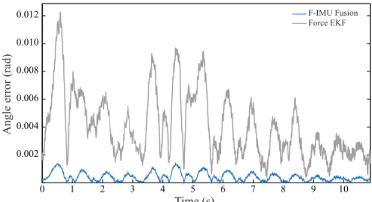
The IMU consistency showed in Figure 8 shows also a more important improvement of the fusion, with an angle of 0.0004 rad instead of 0.0042 rad for Force-EKF.
V. DISCUSSION AND CONCLUSION
We have developed in this paper a dynamical-model based state observer using (i) as given inputs values provided from proprioception and high level control of the robot and (ii) as a corrector the measurements provided by a data fusion of an accelerometer, a gyrometer and a force/torque sensor at each contact point. We have seen through simulation and experimentation that this fusion not only improves naturally the estimation in terms of consistency with sensors measure-ments but may also improve the precision of the estimation itself, by providing precise reconstruction of the Center of Pressure.
These effects of multisensor data fusion involving IMUs are already widely used in robotics for odometry and locali-zation [15], [16], [3], or even stabililocali-zation and control [17], [18]. But few of them to our best knowledge involve also both force sensors and proprioception inside the sensor data fusion. Most works that consider both IMUs and force sensors use the signals separately [19], [20], [21], which means that they mostly use these sensors to reconstruct distinct parts of the state of the robot, which is not properly a full state estimation using fusion. A noticeable exception is the work of Zhang et al [22] who used inertial measurement units and force sensors embedded in a bicycle to reconstruct the state of human rider. Due to lack of proprioceptive data from the human, the authors had to resort to a simplified dynamical model of a spherical inverted pendulum.
Finally, coming back to our method, the inconsistency of measurements are due to modeling errors. This error may lie
0.00 0.01 0.03 -0.01 -0.03 0.02 -0.02 0 1 2 3 4 5 Time (s) Force EKF F-IMU Fusion Sensor Value IMU EKF CoP estimation x position (m)
Fig. 6. Real Robot: the different estimations of thex-position of CoP over time. 0.00 0.01 0.03 -0.01 -0.03 0.02 -0.02 0 1 2 3 4 5 Time (s) Force EKF F-IMU Fusion Sensor Value IMU EKF CoP esimation y position (m)
Fig. 7. Real Robot: the different estimations of they-position of CoP over time.
in the parameters or the linear nature of the viscoelasticity. But it may also be due to a different ground stiffness or inclination from what is expected. Nevertheless, these errors may be observed and corrected in real-time if the relevant parameters are introduced in the state observation. This solution may constitute an interesting future development of our research.
REFERENCES
[1] P.-B. Wieber. On the stability of walking systems. InProceedings of the International Workshop on Humanoid and Human Friendly
Robotics, Tsukuba, Japan, 2002.
[2] M. Benallegue and F. Lamiraux. Humanoid Flexibility Deformation Can Be Efficiently Estimated Using Only Inertial Measurement Units and Contact Information. InIEEE-RAS International Conference on
Humanoid Robots, November 2014.
[3] Michael Bloesch, Marco Hutter, Mark Hoepflinger, Stefan Leuteneg-ger, Christian Gehring, C. David Remy, and Roland Siegwart. State estimation for legged robots - consistent fusion of leg kinematics and IMU. InProceedings of Robotics: Science and Systems, 2012. [4] N. Kanehira, T. Kawasaki, S. Ohta, T. Ismumi, T. Kawada, F.
Kane-hiro, S. Kajita, and K. Kaneko. Design and experiments of advanced leg module (hrp-2l) for humanoid robot (hrp-2) development. In
Intelligent Robots and Systems, volume 3, pages 2455–2460, 2002.
[5] S. Kajita, K. Yokoi, M. Saigo, and K. Tanie. Balancing a humanoid robot using backdrive concerned torque control and direct angular momentum feedback. InICRA, 2001.
[6] S. Kajita, T. Nagasaki, K. Kaneko, K. Yokoi, and K. Tanie. A running controller of humanoid biped hrp-2lr. In Intl. Conf. Robotics and
Automation, (ICRA)., pages 616–622. IEEE, 2005.
0 1 2 3 4 5 6 7 8 9 10 0.002 0.004 0.006 0.008 0.010 0.012 Time (s) Force EKF F-IMU Fusion
Angle error (rad)
Fig. 8. Real Robot: difference between the IMU-EKF flexibility orientation and (i) the F-IMU-Fusion in thin blue, and (ii) the Force-EKF in thick gray lines.
[7] M. Mistry, S. Schaal, and K. Yamane. Inertial parameter estimation of floating base humanoid systems using partial force sensing. In Hu-manoid Robots, 2009. HuHu-manoids 2009. 9th IEEE-RAS International
Conference on, pages 492–497, Dec 2009.
[8] Y. Mikami, T. Moulard, E. Yoshida, and G. Venture. Identification of hrp-2 foot’s dynamics. In Intelligent Robots and Systems IEEE/RSJ
International Conference on, pages 927–932, Sept 2014.
[9] Mehdi Benallegue and Florent Lamiraux. Estimation and stabilization of humanoid flexibility deformation using only inertial measurement units and contact information. International Journal of Humanoid
Robotics, 13(3):1550025–1 to 1550025–20, 2015.
[10] Alexis Mifsud, Mehdi Benallegue, and Florent Lamiraux. Estimation of Contact Forces and Floating Base Kinematics of a Humanoid Robot Using Only Inertial Measurement Units.Accepted in IROS2015, 2015. available at https://hal.archives-ouvertes.fr/hal-01142399.
[11] Fabrizio Caccavale, Ciro Natale, Bruno Siciliano, and Luigi Villani. Six-dof impedance control based on angle/axis representations.IEEE
Transactions on Robotics and Automation, 15(2):289–300, 1999.
[12] C. Ott, M.A. Roa, and G. Hirzinger. Posture and balance control for biped robots based on contact force optimization. In Humanoid Robots (Humanoids), 2011 11th IEEE-RAS International Conference on, pages 26–33, Oct 2011.
[13] The Stack of Tasks Framework. Open source project availabe online at https://github.com/stack-of-tasks.
[14] David L Hall and James Llinas. An introduction to multisensor data fusion. Proceedings of the IEEE, 85(1):6–23, 1997.
[15] B. Gassmann, F. Zacharias, J.M. Zollner, and R. Dillmann. Locali-zation of walking robots. In IEEE International Conference on
Robotics and Automation, pages 1471–1476, April 2005.
[16] M. Reinstein and M. Hoffmann. Dead reckoning in a dynamic quadruped robot: Inertial navigation system aided by a legged odome-ter. In Robotics and Automation (ICRA), 2011 IEEE International
Conference on, pages 617–624, May 2011.
[17] Pei-Chun Lin, H. Komsuoglu, and D.E. Koditschek. Sensor data fusion for body state estimation in a hexapod robot with dynamical gaits.
Robotics, IEEE Transactions on, 22(5):932–943, Oct 2006.
[18] Ryosuke Tajima, Daisaku Honda, and K. Suga. Fast running experi-ments involving a humanoid robot. InRobotics and Automation, IEEE
International Conference on, pages 1571–1576, May 2009.
[19] B.J. Stephens and C.G. Atkeson. Push recovery by stepping for humanoid robots with force controlled joints. InHumanoid Robots
(Humanoids), 2010 10th IEEE-RAS International Conference on,
pages 52–59, Dec 2010.
[20] T. Buschmann, S. Lohmeier, and H. Ulbrich. Biped walking control based on hybrid position/force control. In Intelligent Robots and
Systems, 2009. IROS 2009. IEEE/RSJ International Conference on,
pages 3019–3024, Oct 2009.
[21] S. Kajita, M. Morisawa, K. Miura, S. Nakaoka, K. Harada, K. Kaneko, F. Kanehiro, and K. Yokoi. Biped walking stabilization based on linear inverted pendulum tracking. InIntelligent Robots and Systems
IEEE/RSJ International Conference on, pages 4489–4496, Oct 2010.
[22] Yizhai Zhang, Kuo Chen, and Jingang Yi. Rider trunk and bicycle pose estimation with fusion of force/inertial sensors. Biomedical