10' MIN.
TO FLOOR
Part No. F40BP73110003 Form No. BP7311-3 Revision: 150910 U.L. Model No.: HF948 & HF956
READ AND SAVE THESE INSTRUCTIONS
48” & 56” Industrial Fans
Owner's Manual
HF948BS02
Brushed Steel
HF948W02
Appliance White
Questions, problems, missing parts: Before returning to the store call
Emerson Electric Customer Service - 8 a.m. - 6 p.m., Eastern, Monday-Friday
1-800-654-3545
www.emersonfans.com
Net Weight:
18.7
Lbs.
Model Numbers
HF956BQ02
Barbeque Black
HF956BS02
Brushed Steel
HF956W02
Appliance White
Net Weight:
22.2
Lbs.
Model Numbers
• Español - página 25 • Français - page 49Safety Instructions
TO REDUCE THE RISK OF FIRE, ELECTRICAL SHOCK,OR INJURY TO PERSONS, OBSERVE THE FOLLOWING: a. Use this unit only in a manner intended by the
manufacturer. If you have questions, contact the manufacturer.
b. Before servicing or cleaning unit, switch power off at service panel and lock service panel disconnecting means to prevent power from being switched on accidentally. When the service disconnecting means cannot be locked, securely fasten a warning device, such as a tag, to the service panel.
!
WARNING
Additional Safety Instructions for Installation
1. To avoid possible shock, be sure electricity is turned off at the fuse box before wiring, and do not operate fan without blades.
2. All wiring must be in accordance with the National Electrical Code “ANSI/NFPA 70-2014” and Local Electrical Codes. Use the National Electrical Code if Local Codes do not exist. The ceiling fan must be grounded as a precaution against possible electrical shock. Electrical installation should be made or approved by a licensed electrician.
3. This ceiling suspended fan is intended for permanent electrical connection in an indoor location. Fan must be installed directly to the building structure and capable of withstanding a 50lb. load.
WARNING: The fan must be mounted with the fan blades at least 10 feet from the floor to prevent accidental contact with the fan blades.
4. Always properly connect the retention cable included with this fan as shown in section 4 of this manual. Follow the Instructions carefully.
5. The support beam or joist must be secure and capable of supporting at least 50 pounds.
6. Follow the recommended instructions for the proper method of wiring your ceiling fan. If you do not know enough about electrical wiring, have your fan installed by a licensed electrician.
WARNING: To reduce the risk of electrical shock, this fan must be installed with an isolating wall control/ switch.
NOTE:This fan is suitable for use with solid-state speed controls.
WARNING:To avoid fire, shock or injury, do not use an Emerson or any other brand of control not specifically approved for this fan.
WARNING: This product is designed to use only those parts supplied with this product and/or any accessories designated specifically for use this product by Emerson Electric Co. Substitution of parts or accessories not designated for use with this product by Emerson could result in personal injury or property damage.
WARNING: To reduce the risk of personal injury, do not bend the blade flange when installing the blade flanges, balancing the blades or cleaning the fan. Do not insert foreign objects in between rotating fan blades.
NOTE:All setscrews must be checked and re-tightened where necessary before installation.
1. Read your owner’s manual carefully and keep it for future reference.
2. Be careful of the fan and blades when cleaning, painting, or working near the fan. Always turn off the power to the ceiling fan before servicing.
3. Do not put anything into the fan blades while they are turning.
4. Suitable for use with solid-state speed controls.
READ AND SAVE THESE INSTRUCTIONS
Table of Contents
Section PageSafety Instructions . . . .2 1. Unpacking Instructions . . . .3-4 2. Electrical Requirements . . . .4 3. Ceiling Fan Assembly . . . .5-8 4. How to Hang Your Ceiling Fan . . . .9-11 5. How to Wire Your Ceiling Fan . . . .11-13 6. Wall Control Installation . . . .13-17
Section Page 7. Maintenance . . . .18 8. Accessories . . . .18 9. Troubleshooting . . . .19 10. Repair Parts . . . .20-21 Ceiling Fan Limited Warranty . . . .23 Spanish . . . .25 French . . . .49
3
emersonfans.com Please contact 1-800-654-3545 for further assistance U.L. Model No.: HF948 & HF956
A
E
F
B
C
D
G
1. Unpacking Instructions
This product is designed to use only those parts supplied with this product and/or any accessories designated specifically for use with this product by Emerson Electric Co. Substitution of parts or accessories not designated for use with this product by Emerson Electric Co. could result in personal injury or property damage.
!
WARNING
Do not install or use fan if any part is damaged or missing. Call Toll-Free for replacement parts:
1-800-654-3545
!
WARNING
1.1
Check to see that you have received the following parts:
NOTE: If you are uncertain of part description, refer to
exploded view illustration below.
NOTE: Place the parts from the loose parts bags in a
small container to keep them from being lost.
If any parts are missing, call 1-800-654-3545
for replacement parts before proceeding.
NOTE: IIntermixing blades between fans can cause
excessive wobble. Keep blades in original sets of
three.
1.2
Remove the fan motor assembly from the protective
plastic bag. Place the fan assembly into the upper
styrofoam with the top of the motor facing up.
The upper styrofoam serves as a holder for the fan during
the first stages of assembly.
PACKAGE CONTENTS
4
2
5
7
8
1
3
6
9
Part Description Quantity
A Motor Assembly 1
B Upper Canopy 1
C Lower Canopy 1
D 22” Hanger Pipe with Hanger Assembly 1
E 8” Hanger Pipe (HF948 Only) 1
F Contoured Metal Fan Blades 3
G SW95 Wall Control Switch & Hardware 1
HARDWARE BAG CONTENTS
Part Description Quantity
1 Clevis Pin 1
2 Hairpin Clip 1
3 Wire Connectors 3
4 M6 x 1/2” Hex Head Blade Screws 6
5 M6 Spring Washers 6
6 5/16-18 x 1/4” Setscrews 2
7 Blade Gaskets 3
8 Cable Clamps 2
9 Allen Wrench 1
10
11
12
13
J-HOOK HARDWARE BAG CONTENTS
Part Description Quantity
10 J-Hooks 2
11 Flat Washers 2
12 Lock Washers 2
IMPORTANT: Your ceiling fan will not function
properly, and may be damaged, if used with any wall
dimmer switch or control other than an Emerson
Electric Fan Wall Control.
Please call Emerson technical support at
1-800-654-3545 if you have any questions about
installation and operation of this ceiling fan.
Before assembling your ceiling fan, refer to section on proper method of wiring your fan (page 11). If you feel you do not have enough wiring knowledge or experience, have your fan installed by a licensed electrician.
!
WARNING
This Manual Is Designed to Make it as Easy as Possible for
You to Assemble, Install, Operate and Maintain Your Ceiling Fan
Tools Needed for Assembly
One stepladder
One wire stripper
Drill
Materials
Wiring outlet box and box connectors must be of type
required by the local code. The minimum wire would be a
3-conductor (2-wire with ground) of following size:
Installed Wire Length Wire Size A.W.G.
Up to 50 ft. 14
50-100 ft. 12
2. Electrical Requirements
Your new ceiling fan will require a grounded electrical
supply line of 120 volts AC, 60 Hz, 15 amp circuit.
Turning off wall switch is not sufficient. To avoid possible electrical shock, be sure electricity is turned off at the main fuse box before wiring. All wiring must be in accordance with National and Local codes and the ceiling fan must be properly grounded as a precaution against possible electrical shock.
!
WARNING
To avoid fire or shock, follow all wiring instructions carefully.
Any electrical work not described in these instructions should be done or approved by a licensed electrician.
!
WARNING
5
emersonfans.com Please contact 1-800-654-3545 for further assistance U.L. Model No.: HF948 & HF956
3. Ceiling Fan Assembly
HANGER PIPE ASSEMBLY LOWER CANOPY UPPER CANOPY Figure 2
3.2
Place the upper canopy and lower canopy on the hanger
pipe assembly, facing in the proper direction. (Figure 2).
HANGER PIPE ASSEMBLY MOTOR WIRE (3) RETENTION CABLE (1) Figure 3
3.3
Pass the motor wires and retention cable through the
hanger pipe assembly (Figure 3).
LOCKWASHER HEX NUT HAIRPIN CLIP CLEVIS PIN BOLT HANGER PIPE HANGER ASSEMBLY Figure 1
3.1
NOTE: For HF948 Only. If you are going to use the
8” hanger pipe, first remove the hanger assembly from
the 22” hanger pipe and install it on the 8” hanger pipe
(Figure 1).
Be sure that the lockwasher and hex nut are securely
tightened and the hairpin clip properly installed onto
the clevis pin bolt to secure the hanger assembly to
the hanger pipe.
3. Ceiling Fan Assembly
(Continued)
HAIRPIN CLIP CLEVIS PIN MOTOR YOKE HANGER PIPE RUBBER GROMMET Figure 53.5
Align the clevis pin holes in the hanger pipe with the holes
in the motor yoke.
Install the clevis pin and secure with the hairpin clip (Figure
5).
The clevis pin must go through the holes in the motor yoke
and the holes in the hanger pipe.
Push the straight leg of the hairpin clip through the hole
near the end of the clevis pin until the curved portion of the
hairpin clip snaps around the clevis pin.
The hairpin clip must be properly installed to prevent the
clevis pin from working loose.
Pull on the rubber grommet to make sure the clevis pin is
properly installed.
It is critical that the clevis pin in the motor coupling is properly installed. Failure to verify that the pin is properly installed (as shown in Figure 5) could result in the fan falling.
!
WARNING
MOTOR YOKE HANGER PIPE Figure 43.4
Seat the hanger pipe in the motor yoke (Figure 4).
CANOPIES NOT SHOWN FOR CLARITY CANOPIES NOT SHOWN
7
emersonfans.com Please contact 1-800-654-3545 for further assistance U.L. Model No.: HF948 & HF956
MOTOR YOKE HANGER PIPE 5/16-18 SETSCREW (2) ALLEN WRENCH Figure 6
3.6
Install and securely tighten the two 5/16-18 setscrews in
the motor yoke against the hanger pipe using the allen
wrench, supplied (Figure 6).
It is critical that the setscrews are securely tightened. Failure to verify that the setscrews are properly installed (as shown in Figure 5) could result in the fan falling.
!
WARNING
3. Ceiling Fan Assembly
(Continued)
MOTOR ASSEMBLY LOWER CANOPY
LOWER CANOPY COLLAR HANGER PIPE
ALLEN WRENCH SETSCREW
Figure 7
3.7
Slide the lower canopy down the hanger pipe and securely
tighten the setscrew on the lower canopy collar against the
hanger pipe using the supplied allen wrench (Figure 7).
BLADE GASKETS (3) MOTOR ASSEMBLY
Figure 8
3.8
CAUTION: Blades come in balanced sets of three. Do
not mix blades if installing more than one fan.
Install the three blade gaskets onto the motor assembly in
preparation of blade assembly (Figure 8).
CANOPIES NOT SHOWN FOR CLARITY
3. Ceiling Fan Assembly
(Continued)
To reduce the risk of personal injury, do not bend the blade flanges when installing the blades, balancing the blades, or cleaning the fan. Do not insert foreign objects between rotating fan blades.
!
WARNING
BLADE ASSEMBLIES (3) BLADE GASKETS (3) SPRING WASHER (2 PER BLADE) M6 x 1/2" SCREW (2 PER BLADE) Figure 93.9
Install one non-reversible blade assembly onto the motor
housing using two spring washers and two
M6 x 1/2" screws, supplied (per blade) (Figure 9).
Repeat this procedure for each of the three blade
assemblies.
Tighten each blade screw to secure each blade assembly
to the motor housing.
9
emersonfans.com Please contact 1-800-654-3545 for further assistance U.L. Model No.: HF948 & HF956
CEILING
FLOOR
10 FOOT MINIMUM
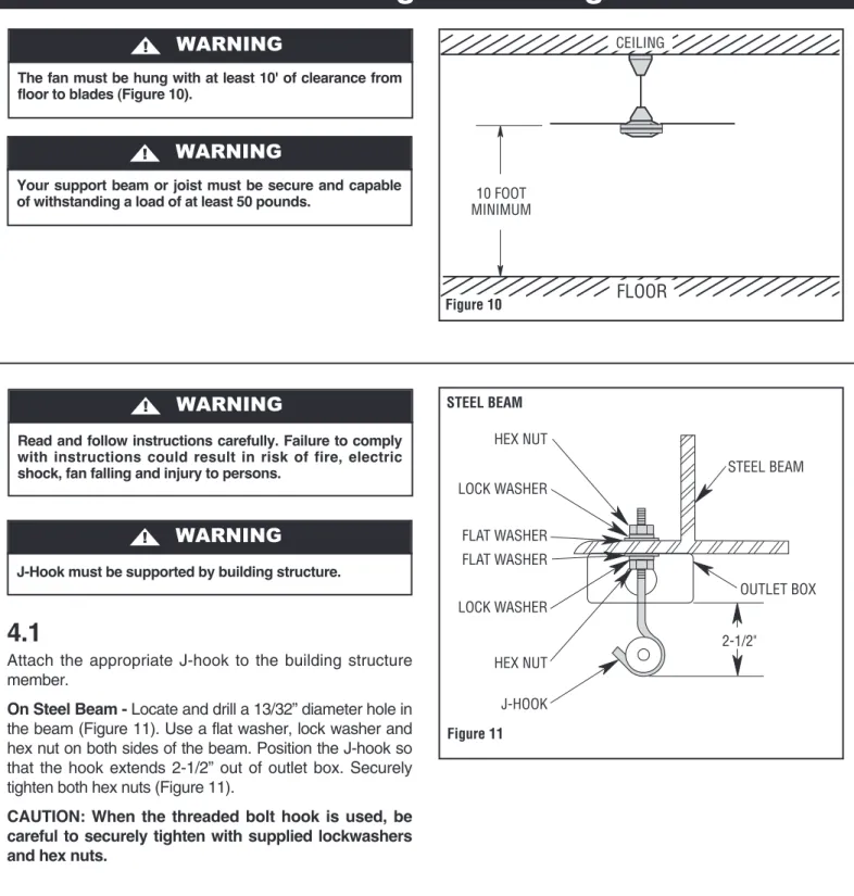
Figure 10 The fan must be hung with at least 10' of clearance from
floor to blades (Figure 10).
!
WARNING
Your support beam or joist must be secure and capable of withstanding a load of at least 50 pounds.
!
WARNING
4.1
Attach the appropriate J-hook to the building structure
member.
On Steel Beam -
Locate and drill a 13/32” diameter hole in
the beam (Figure 11). Use a flat washer, lock washer and
hex nut on both sides of the beam. Position the J-hook so
that the hook extends 2-1/2” out of outlet box. Securely
tighten both hex nuts (Figure 11).
CAUTION: When the threaded bolt hook is used, be
careful to securely tighten with supplied lockwashers
and hex nuts.
Read and follow instructions carefully. Failure to comply with instructions could result in risk of fire, electric shock, fan falling and injury to persons.
!
WARNING
J-Hook must be supported by building structure.
!
WARNING
HEX NUT LOCK WASHER FLAT WASHER OUTLET BOX STEEL BEAM 2-1/2" FLAT WASHER LOCK WASHER HEX NUT J-HOOK Figure 114. How to Hang Your Ceiling Fan
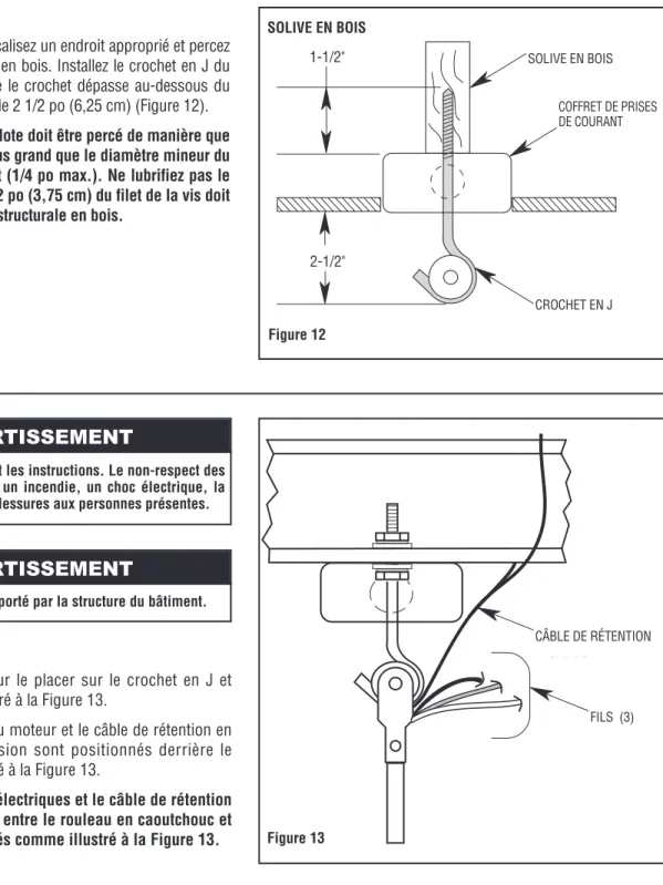
J-HOOK 2-1/2" 1-1/2" OUTLET BOX WOOD JOIST Figure 12
4.3
Lift the fan onto the J-hook and position as shown in
Figure 13.
Make sure the motor wires and retention cable at the top of
the hanger pipe are positioned behind J-hook as illustrated
in Figure 13.
CAUTION: The electrical wires and retention cable
must not be placed between the rubber roller and the
hook, but rather as illustrated in Figure 13.
4.2
On Wood Joist -
Locate and drill a pilot hole in the wood
joist. Install the screw type J-hook so that hook extends
2-1/2” below the outlet box (Figure 12).
CAUTION: The pilot hole should be drilled no larger
than the minor diameter of the screw threads on the
hook (1/4” max.). Do not put a lubricant on the
J-hook. At least 1-1/2” of the screw threads should be
secured into the structural wood joist.
Read and follow instructions carefully. Failure to comply with instructions could result in risk of fire, electric shock, fan falling and injury to persons.
!
WARNING
J-Hook must be supported by building structure.
!
WARNING
RETENTION CABLE
WIRES (3)
Figure 13
4. How to Hang Your Ceiling Fan
(Continued)
11
emersonfans.com Please contact 1-800-654-3545 for further assistance U.L. Model No.: HF948 & HF956
4.4
This fan is equipped with the required retention cable.
This cable must be affixed to the building structure and
securely clamped in such a manner to support the weight
of the fan in the event the mounting hook or other parts fail.
After wrapping cable around or to a structural member that
will support 50 pounds, secure cable with supplied cable
clamps as illustrated in Figure 14.
NOTE: Leave approximately 3" but no more than 5" of
slack on this safety cable to allow for possible fan
movement. Do not exceed more than 5" total slack.
CAUTION: It is important to note the proper
installation position of the cable clamps as illustrated
in Figure 14. To obtain maximum holding power,
install U-bolt section of clip on dead or short end of
cable and saddle on long end of cable. Improper
installation reduces the efficiency of the connection by
as much as 40 percent.
TO SUPPORT STRUCTURE TO FAN CABLE CLAMPS (2) RETENTION CABLE Figure 144. How to Hang Your Ceiling Fan
(Continued)
If you feel that you do not have enough electrical
wiring knowledge or experience, have your fan
installed by a licensed electrician.
5.1
Connect the green grounding wire from the fan motor to
the green grounding wire from the supply source (this may
be a bare wire or wire with green colored insulation).
Securely connect wires with a wire connector (supplied)
(Figure 15).
CAUTION: Use larger U.L. listed wire connectors if
supply source wires are larger than #12 AWG.
5. How to Wire Your Ceiling Fan
To avoid possible electrical shock, be sure electricity is turned off at the main fuse box before wiring.
NOTE: If you are not sure if the outlet box is grounded, contact a licensed electrician for advice, as it must be grounded for safe operation.
!
WARNING
This product is designed to use only those parts supplied with this product and/or any accessories designated specifically for use with this product by Emerson Electric Co. Substitution of parts or accessories not designated for use with this product by Emerson Electric Co. could result in personal injury or property damage.
!
WARNING
SUPPLY GROUND WIRE GREEN WIRE (GROUND) FROM FAN WIRE CONNECTOR Figure 155.2
Securely connect the fan motor white wire to the supply
white (neutral) wire using a wire connector supplied
(Figure 16).
5. How to Wire Your Ceiling Fan
(Continued)
WIRE CONNECTOR WHITE WIRE FROM FAN SUPPLY WHITE (NEUTRAL) WIRE
Figure 16
5.3
Securely connect the fan motor black (hot) wire to the
supply black wire (hot) using a wire connector supplied
(Figure 17).
WIRE CONNECTOR SUPPLY BLACK (HOT) WIRE
BLACK WIRE FROM FAN
Figure 17
5.4
After connections have been made, turn leads upward
and carefully push leads into the outlet box, with the white
and green leads on one side of the outlet box and the
black leads on the other side of the outlet box (Figure 18).
GREEN WIRES WHITE WIRES BLACK WIRES
OUTLET BOX
Check to see that all connections are tight, including ground, and that no bare wire is visible at the wire connectors, except for the ground wire.
CAUTION: Do not operate fan until blades are in place. Noise and fan damage could result.
!
WARNING
To avoid possible fire or shock, make sure that the electrical wires are completely inside the outlet box and not pinched between the ceiling cover and the ceiling.
!
WARNING
13
emersonfans.com Please contact 1-800-654-3545 for further assistance U.L. Model No.: HF948 & HF956
5. How to Wire Your Ceiling Fan
(Continued)
5.5
Slide the upper canopy up the rod within 1/4" of the ceiling
or beam and securely tighten the setscrew (Figure 19).
UPPER CANOPY
SETSCREW
Figure 19
6. Wall Control Installation
6.1
General Information
The SW95 Wall Control is designed to operate only
one ceiling fan, and Not an accessory light kit.
The SW95 Wall Control is rated for 1.25 Amp, 120
VAC, 60 HZ full load.
All ceiling fans must be completely installed before
installation of the Wall Control.
Your new Wall Control will require a grounded
electrical supply line of 120 volts AC, 60 HZ circuit.
NOTE: Do not install a solid state electronic romote
control with the SW95 wall control installed, damage
to the fan motor could result.
6.2
Installation of Wall Control replacing an
Existing Wall Control:
Disconnect electrical power to the branch circuit at the
circuit breaker or fuse box before attempting to install the
ceiling fan mounting plate on the outlet box.
Turning off wall switch is not sufficient. To avoid possible electrical shock, be sure electricity is turned off at the main fuse box before wiring. All wiring must be in accordance with National and Local codes and the ceiling fan must be properly grounded as a precaution against possible electrical shock.
6-3 SCREWS (2) FACEPLATE WALL OUTLET BOX
SWITCH
Figure 20
6. Wall Control Installation
(Continued)
6.3
Remove the faceplate and the two 6-32 screws from the
existing wall switch (retain faceplate and screws for future
use) (Figure 20).
6.4
Pull existing wall switch out from the wall outlet box.
Disconnect the existing wall switch wires from the wires in
the outlet box by removing the the two wire connectors
(discard connectors) (Figure 21).
NEUTRAL LEAD WIRES
SCREWS (2) WALL OUTLET BOX WIRE
CONNECTOR (2)
EXISTING WALL SWITCH
Figure 21
6.5
Set the new Wall Control in the OFF position (full
counter-clockwise) (Figure 22).
15
emersonfans.com Please contact 1-800-654-3545 for further assistance U.L. Model No.: HF948 & HF956
TO 120VAC SOURCE HOT TO FAN MOTOR LOAD FAN/MOTOR BLACK OR RED WIRE WIRE CONNECTOR WALL CONTROL BLACK WIRE WALL CONTROL Figure 23
6. Wall Control Installation
(Continued)
6.6
Connect the Wall Control BLACK wire to the Fan/Motor
Lead (BLACK or RED) wire using a new wire connector
(supplied) (Figure 23).
NOTE: Use only the wire connectors supplied with the
new wall control to secure electrical connections.
6.7
Connect the Wall Control BLACK wire to the 120 VAC
source hot BLACK wire using a new wire connector
(supplied) (Figure 24).
WALL CONTROL BLACK WIRE 120 VAC HOT BLACK WIRE WALL CONTROL WIRE CONNECTOR TO 120VAC SOURCE HOT TO FAN MOTOR LOAD Figure 246.8
Securely connect the GREEN ground wire from the Wall
Control to the supply ground wire (bare or green
(Figure 25).
WALL CONTROL GREEN GROUND WIRE WIRE CONNECTOR SUPPLY GREEN GROUND WIRE Figure 25 Check to see that all wire connections are tight, includingground, and that no bare wire is visible at the wire connectors, except for ground.
TO 120VAC SOURCE HOT
TO FAN MOTOR LOAD
DO NOT CONNECT ANY WIRES FROM WALL CONTROL TO THESE WHITE
NEUTRAL WIRES
Figure 26
6. Wall Control Installation
(Continued)
6.9
NOTE: The WHITE neutral wires inside the electrical
box must be connected together for proper operation
of the wall control. NEVER connect the WHITE neutral
wires to the Wall Control (Figure 26).
6.10
Carefully tuck all wires and wire connectors into the outlet
box and position the Wall Control onto the outlet box
(Figure 27).
POSITION THE WALL CONTROL INTO THE OUTLET BOX
WALL CONTROL
WIRES TUCKED INTO OUTLET BOX
Figure 27
6.11
Place the previously removed faceplate onto the Wall
Control.
Assemble the faceplate to the Wall Control using the two
previously removed 6-32 screws (Figure 28).
Do not connect any neutral (WHITE) wire to this control. Incorrect wiring WILL damage this control.
17
emersonfans.com Please contact 1-800-654-3545 for further assistance U.L. Model No.: HF948 & HF956
KNOB
WALL CONTROL
Figure 29
6. Wall Control Installation
(Continued)
6.12
The Wall Control is supplied with a white and almond
knob. Select the knob that matches the color of existing
faceplate (Figure 29).
Press knob onto the shaft of the Wall Control.
Rotate knob counter-clockwise to the full OFF position.
To Complete Installation:
Restore power at the main
fuse box or circuit breaker panel.
6.13
SW95 Single Fan Wall Control Wiring (Figure 30).
TO NEUTRAL TO FAN MOTOR LOAD
TO 120VAC SOURCE HOT SW95 SINGLE FAN WALL CONTROL BLACK BLACK BLACK or RED BLACK GREEN GREEN Figure 30
6.14
After completing installation, test run fan in normal
operation manner. Inspect for any possible shake or
wobble which may be caused by binding as a result of
"tight cable". if this should happen, shut off power supply
and re-check instructions to correct problem.
NOTE: When any solid state motor speed control is
used, a humming noise may be present in the fan on
low speed. This hum in no way affects the operation
of the fan and is acceptable in most installations.
This product is designed to use only those parts supplied with this product and/or any accessories designated specifically for use with this product by Emerson Electric Co. Substitution of parts or accessories not designated for use with this product by Emerson Electric Co. could result in personal injury or property damage.
!
WARNING
See your local Emerson dealer, www.emersonfans.com or
the Emerson Ceiling Fan catalog for these accessories:
· Ceiling Fan/Light Controls
· Hanger Pipe (Downrod) Extension Kits
· Suitable for use with Emerson Solid-State Speed
Control
8. Accessories
The use of any other control not specifically approved for this fan could result in fire, shock and personal injury.
!
WARNING
Do not use water when cleaning your ceiling fan. It could damage the motor or the blades and create the possibility of an electrical shock.
!
WARNING
IMPORTANT CARE INSTRUCTIONS
for your Ceiling Fan
Periodic cleaning of your new ceiling fan is the only
maintenance that is needed.
When cleaning, use only a soft brush or lint free cloth to
avoid scratching the finish.
Abrasive cleaning agents are not required and should be
avoided to prevent damage to finish.
LUBRICATION -
All bearings are permanently lubricated
and do not require further lubrication.
CLEANING -
This fan may be wiped off with a damp cloth.
Do not allow the motor to get wet. Do not use solvents or
harsh detergents.
19
emersonfans.com Please contact 1-800-654-3545 for further assistance U.L. Model No.: HF948 & HF956
WARNING:
FOR YOUR OWN SAFETY TURN OFF POWER AT FUSE BOX OR CIRCUIT BREAKER BEFORE
TROUBLESHOOTING YOUR FAN.
!!
!
TROUBLE PROBABLE CAUSE SUGGESTED REMEDY 1. Fan will not start. 1. Fuse or circuit breaker blown. 1. Check main and branch circuit fuses or circuit breakers.
2. Loose power line connections to the fan, 2. Check all wire connections on the fan or loose switch wire connections in the for loose wires.
upper canopy. WARNING:Turn off the electricity before attempting to service the ceiling fan. 2. Fan sounds noisy. 1. Blades not attached to fan. 1. Attach blades to fan before operating.
2. Loose screws in motor housing. 2. Check to make sure all screws in motor housing are snug (not over-tight).
3. Screws securing fan blade flanges to 3. Check to make sure the screws which attach motor hub are loose. the fan flanges to the motor hub are tight. WARNING:Turn off the electricity before attempting to service the ceiling fan. 3. Fan wobbles 1. Setscrews in motor coupling are loose. 1. Tighten both setscrews securely in the motor excessively. coupling.
2. Setscrew in hanger ball / hanger pipe 2. Tighten the setscrew in the hanger ball / hanger pipe assembly is loose. assembly.
3. Hanger bracket and / or ceiling outlet 3. Tighten the hanger bracket screws to the outlet box is not securely fastened. box, and / or secure outlet box.
4. Fan blades out of balance. 4. Interchanging an adjacent (side-by-side) blade pair can redistribute the weight and result in smoother operation.
10. Repair Parts
1
2
4
5
6
11
12
18
14
13
17
15
7
16
3
Before discarding packaging material, be certain all parts have been removed.
HOW TO ORDER REPAIR PARTS
WHEN ORDERING REPAIR PARTS, ALWAYS GIVE THE FOLLOWING INFORMATION:
• PART NUMBER • NAME OF ITEM
• PART DESCRIPTION • MODEL NUMBER
The model number of your Fan will be found on a label attached to the top housing.
For repair parts, phone 1-800-654-3545.
10. Repair Parts Listing
Model Numbers
Key
No. Description HF948BS02 HF948W02 HF956BQ02 HF956BS02 HF956W02
1 J-Hook Bag Assembly: 761385 761385 761385 761385 761385
J-Hooks (2 each) — — — — —
Hardware (2 each) — — — — —
2 Hanger Assembly 761339 761339 761339 761339 761339
3 Hanger Pipe (8”) (HF948 Only) 761387-5 761387-2 — — —
4 Hanger Pipe (22”) 761387-6 761387 761387-BQ 761387-7 761387
5 Upper Canopy 761335-BS 761335 761335-BQ 761335-BS 761335
6 Lower Canopy 761336-BS 761336 761336-BQ 761336-BS 761336
7 Blades (Set of 3) 763095-BS 763095 763094-BQ 763094-BS 763094
8 Capacitor — — — — —
9 Wall Control/Hardware SW95 SW95 SW95 SW95 SW95
* Parts Bag, Containing: 761384 761384 761384 761384 761384
10 5/16-18 x 1/4” Setscrews (2 ea.) — — — — —
11 Hairpin Clip — — — — —
12 Clevis Pin — — — — —
13 Cable Clamp (2 each) — — — — —
14 Screw, M6 x 1/2” (6 each) — — — — —
15 Spring Washer, M6 (6 each) — — — — —
16 Blade Gasket (3 each) — — — — —
17 Wire Connector (3 each) — — — — —
18 Allen Wrench — — — — —
— Owner's Manual BP7311-3 BP7311-3 BP7311-3 BP7311-3 BP7311-3
21
emersonfans.com Please contact 1-800-654-3545 for further assistance U.L. Model No.: HF948 & HF956
23
emersonfans.com Please contact 1-800-654-3545 for further assistance U.L. Model No.: HF948 & HF956
What The Limited Warranty Covers:
This limited warranty is offered by Air Comfort Products division of Emerson Electric Co. ("Emerson" "we"or "us") located at the address stated below to the original retail purchaser ("you"or "your") of an Emerson Air Comfort Ceiling Fan product ("Emerson Ceiling Fan") and covers the motor and the other components and accessories of the Emerson Ceiling Fan against all defects in workmanship and materials.
What The Period Of Coverage Is:
This limited warranty will cover the Emerson Ceiling Fan motor for the expected lifetime of your Emerson Ceiling Fan (when operated in accordance with your Owner's Manual or other instructions provided by Emerson to you with the Emerson Ceiling Fan). All other components and accessories of the Emerson Ceiling Fan are covered by this limited warranty for a period of one (1) year from its date of original retail purchase. ANY IMPLIED WARRANTY, INCLUDING WITHOUT LIMITATION, ANY IMPLIED WARRANTY OF MERCHANTABILITY OR FITNESS FOR A PARTICULAR PURPOSE THAT IS AVAILABLE TO YOU UNDER THE LAWS OF YOUR STATE OR PROVINCE SHALL COVER THE MOTOR FOR THE EXPECTED LIFETIME OF THE MOTOR (SUBJECT TO PROPER USE), AND FOR ONE YEAR WITH RESPECT TO COMPONENTS AND ACCESSORIES.
No Other Express or Implied Warranty Applies:
THE LIMITED WARRANTIES PROVIDED ABOVE ARE THE SOLE AND EXCLUSIVE WARRANTIES PROVIDED BY EMERSON TO YOU FOR YOUR EMERSON CEILING FAN, AND ARE IN LIEU OF ALL OTHER WARRANTIES, WRITTEN OR ORAL, EXPRESS OR IMPLIED, WHETHER ARISING BY OPERATION OF LAW OR OTHERWISE, WHETHER OR NOT THE PURPOSE HAS BEEN DISCLOSED AND WHETHER OR NOT THE EMERSON CEILING FAN HAS BEEN SPECIFICALLY DESIGNED OR MANUFACTURED FOR YOUR USE OR PURPOSE. EMERSON HEREBY DISCLAIMS ANY AND ALL IMPLIED WARRANTIES, INCLUDING WITHOUT LIMITATION, IMPLIED WARRANTIES OF MERCHANTABILITY OR FITNESS FOR A PARTICULAR PURPOSE FOR COMPONENTS AND ACCESSORIES AS OF THE EXPIRATION OF THE ONE YEAR WARRANTY PERIOD FOR SUCH COMPONENTS AND ACCESSORIES. IMPLIED WARRANTIES OF MERCHANTABILITY OR FITNESS FOR A PARTICULAR PURPOSE FOR THE MOTOR PORTION OF THE EMERSON CEILING FAN ARE LIKEWISE DISCLAIMED BY EMERSON AT SUCH TIME THAT THE EXPECTED LIFETIME OF THE EMERSON CEILING FAN UNDER NORMAL USAGE HAS BEEN REACHED. EXCLUSIONS OR LIMITATIONS OF IMPLIED WARRANTIES MAY VARY FROM STATE TO STATE AND PROVINCE TO PROVINCE SO THE ABOVE LIMITATIONS MAY NOT APPLY TO YOU.
What We Will Do To Correct Problems:
If during the one (1) year warranty period the motor or any component or accessory of your Emerson Ceiling Fan is defective in materials or workmanship, or if during the expected lifetime of the Emerson Ceiling Fan (when used in accordance with the User Manual or other instructions) the motor is defective in materials or workmanship, you must contact Emerson during the applicable warranty period. If the defect is covered by warranty, Emerson will repair or replace the defective motor, component or other accessory at no charge to you. If repair of the motor, component or accessory is not practical or possible within a reasonable time and no replacement Emerson Ceiling Fan can be provided, Emerson will refund to you the actual purchase price of your Emerson Ceiling Fan. We will ship the repaired or the replacement Emerson Ceiling Fan to you at no charge, but you are responsible for all costs of removal and reinstallation of your Emerson Ceiling Fan.
How You Can Receive Warranty Service:
You must be the original retail purchaser and have proof of your purchase of the Emerson Ceiling Fan to obtain your remedy under this limited warranty. You can return your Emerson Ceiling Fan to your place of purchase, or you can call Emerson Customer Service at 1-800-237-6511 to obtain a return authorization and service identification tag. In order for us to confirm that your Emerson Ceiling Fan is still under warranty, please retain your receipt or other proof of purchase and have that information readily available when returning your Emerson Ceiling Fan to your place of purchase, or upon calling Emerson Customer Service. If you call Emerson Customer Service, prior to your call please be prepared to provide all model numbers shown on your Emerson Ceiling Fan. Once we have processed your return authorization request, we will provide you with a postage paid return label which should be affixed to the Emerson Ceiling Fan package you ship to the address listed at the end of this limited warranty. The return label will be sent to the mailing address you provide to us by phone.
What Is Not Covered:
This limited warranty does not extend to and expressly excludes: • The glass globes and light bulbs of your Emerson Ceiling Fan,
• Loss or damage to the motor or any component or accessory caused by normal wear and tear, rather than due to defects in materials or workmanship,
• Loss or damage resulting from conditions beyond our reasonable control, including without limitation, repairs not made at our factory or authorized service center, use of parts or accessories not provided to you as part of this warranty by our factory or authorized service center, mishandling, unreasonable use, misuse, abuse, modifications or other damage caused by you or a third party to your Emerson Ceiling Fan while not in our possession,
• Loss or damage resulting from improper installation, or other failure to comply with instructions in your Owner's Manual. This limited warranty is deemed null and void upon the occurrence of either of the following events:
• You cease to own the Emerson Ceiling Fan product, or
• The Emerson Ceiling Fan is moved from its original point of installation.
This limited warranty is only valid within the 50 United States, the District of Columbia, and Canada. No other written or oral warranties apply, and no employee, agent, dealer or other person is authorized to give any warranties on behalf of Air Comfort Products or Emerson Electric Co.
Limitation of Liability
REPAIR, REPLACEMENT OR A REFUND ARE THE EXCLUSIVE REMEDIES AVAILABLE TO YOU UNDER THIS LIMITED WARRANTY. TO THE EXTENT PERMITTED BY LAW, IN NO EVENT SHALL EMERSON OR ANY EMERSON AUTHORIZED DEALER BE LIABLE FOR ANY INCIDENTAL, SPECIAL, INDIRECT, OR CONSEQUENTIAL DAMAGES, INCLUDING ANY ECONOMIC LOSS, WHETHER RESULTING FROM NONPERFORMANCE, USE, MISUSE OR INABILITY TO USE THE EMERSON CEILING FAN OR FOR THE NEGLIGENCE OF EMERSON OR AN EMERSON AUTHORIZED DEALER. EMERSON SHALL NOT BE LIABLE FOR DAMAGES CAUSED BY DELAY IN PERFORMANCE AND IN NO EVENT, REGARDLESS OF THE FORM OF THE CLAIM OR CAUSE OF ACTION (WHETHER BASED IN CONTRACT, INFRINGEMENT, NEGLIGENCE, STRICT LIABILITY, OTHER TORT OR OTHERWISE), SHALL EMERSON'S OR ANY EMERSON AUTHORIZED AGENT'S LIABILITY TO YOU OR ANY INDIVIDUAL USING THE EMERSON CEILING FAN EXCEED THE PRICE PAID BY THE ORIGINAL OWNER FOR THE EMERSON CEILING FAN. The term "consequential damages" shall include, but not be limited to, loss of anticipated profits, business interruption, loss of use or revenue, cost of capital or loss or damage to property or equipment.
How State and Provincial Law Relates To The Warranty:
Some states and provinces do not allow the exclusion or limitation of incidental or consequential damages so the above exclusion or limitation may not apply to you. This limited warranty gives you specific legal rights, and you may also have other rights which vary from state to state or province to province.
Questions, problems, missing parts: Before returning to the store call
Emerson Electric Customer Service
8 a.m. - 6 p.m., Eastern, Monday-Friday
Air Comfort Products
DIVISION OF EmErSON ElEctrIc cO.
8100 W. Florissant • St. louis, mO 63136
10' MIN.
TO FLOOR
No. de pieza F40BP73110003 No. de formulario BP7311-3 Revisión: 150910 No. de modelo U.L.: HF948 y HF956
LEA Y GUARDE ESTAS INSTRUCCIONES
Manual del usuario de ventiladores
industriales de 48 y 56 pulgadas
HF948BS02
Acero cepillado
HF948W02
Blanco
electrodoméstico
Preguntas, problemas, piezas faltantes: Antes de devolver el producto a la tienda, llame a
Servicio al Cliente de Emerson Electric 8 a.m. a 6 p.m., Hora del Este, lunes a viernes
1-800-654-3545
www.emersonfans.com
Peso neto:
18,7
lb.
Números de modelo
HF956BQ02
Negro barbacoa
HF956BS02
Acero cepillado
HF956W02
Blanco
electrodoméstico
Peso neto:
22,2
lb.
Números de modelo
• Français - page 4910 PIES HASTA
EL PISO COMO
MÍNIMO
Instrucciones de seguridad
PARA REDUCIR EL RIESGO DE INCENDIO, DESCARGAS ELÉCTRICAS O LESIONES A LAS PERSONAS, HAGA CASO DE LO SIGUIENTE:
a. Utilice esta unidad sólo de la manera prevista por el fabricante. Si tiene preguntas, contacte al fabricante.
b. Antes de hacer servicio de ajustes y reparaciones de la unidad o de limpiarla, ponga el interruptor en la posición de apagado en el panel de servicio y bloquee los medios de desconexión de dicho panel para impedir que la unidad se encienda accidentalmente. Cuando los medios de desconexión de servicio no se puedan bloquear, sujete firmemente un dispositivo de advertencia, como por ejemplo una etiqueta, en el panel de servicio.
ADVERTENCIA
3. Este ventilador suspendido del techo está diseñado paraconexión eléctrica permanente en un lugar interior. El ventilador se debe instalar directamente en la estructura del edificio y ser capaz de resistir una carga de 50 lb.ADVERTENCIA: El ventilador se debe montar con sus paletas por lo menos a 10 pies del piso, para prevenir un contacto accidental con las paletas del ventilador.
4. Conecte siempre adecuadamente el cable de retención incluido con este ventilador, tal y como se muestra en la sección 4 de este manual. Siga minuciosamente las instrucciones.
5. La viga o vigueta de soporte debe estar firmemente sujeta y ser capaz de soportar por lo menos 50 libras.
6. Siga las instrucciones recomendadas para el método apropiado de cablear su ventilador de techo. Si no sabe lo suficiente sobre cableado eléctrico, haga que un electricista con licencia instale su ventilador.
ADVERTENCIA: Para reducir el riesgo de descargas eléctricas, este ventilador se debe instalar con un control/interruptor de pared con aislamiento.
NOTA:Este ventilador es adecuado para utilizarse con controles de velocidad de estado sólido.
ADVERTENCIA: Para evitar incendios, descargas eléctricas o lesiones, no utilice un control Emerson o de cualquier otra marca que no esté aprobado específicamente para este ventilador.
ADVERTENCIA: Este producto está diseñado para utilizarse sólo con las piezas suministradas con este producto y/o los accesorios diseñados específicamente por Emerson Electric Co. para utilizarse con este producto. La sustitución con piezas o accesorios no diseñados por Emerson para utilizarse con este producto podría causar lesiones corporales o daños materiales.
ADVERTENCIA: Para reducir el riesgo de lesiones corporales, no doble las pestañas de la paleta cuando instale dichas pestañas, equilibre las paletas o limpie el ventilador. No inserte objetos extraños entre las paletas del ventilador que giran.
NOTA:Todos los tornillos de ajuste se deben revisar y reapretar donde sea necesario antes de realizar la instalación.
1. Lea detenidamente el manual del usuario y guárdelo para referencia futura.
2. Tenga cuidado con el ventilador y las paletas cuando limpie el ventilador, lo pinte o trabaje cerca de él. Apague siempre el suministro eléctrico al ventilador de techo antes de hacerle servicio de ajustes y reparaciones.
3. No ponga nada en las paletas del ventilador mientras estén girando. 4. Este ventilador es adecuado para utilizarse con controles de velocidad
de estado sólido.
Instrucciones de seguridad adicionales
para la instalación
1. Para evitar posibles descargas eléctricas, asegúrese de que la electricidad esté desconectada en la caja de fusibles antes de realizar el cableado, y no utilice el ventilador sin paletas.
2. Todo el cableado se debe realizar de acuerdo con el Código Eléctrico Nacional “ANSI/NFPA 70-2014” y los Códigos Eléctricos Locales. Utilice el Código Eléctrico Nacional si no existen Códigos Locales. El ventilador de techo se debe conectar a tierra como precaución contra posibles descargas eléctricas. La instalación eléctrica deberá ser realizada por un electricista aprobado o con licencia.
LEA Y GUARDE ESTAS INSTRUCCIONES
Índice
Sección Página
Instrucciones de seguridad . . . .26 1. Instrucciones de desempaquetado . . . .27-28 2. Requisitos eléctricos . . . .28 3. Ensamblaje del ventilador de techo . . . .29-32 4. Cómo colgar su ventilador de techo . . . .33-35 5. Cómo cablear su ventilador de techo . . . .35-37 6. Instalación del control de pared . . . .37-41
Sección Página
7. Mantenimiento . . . .42 8. Accesorios . . . .42 9. Resolución de problemas . . . .43 10. Piezas de repuesto . . . .44-45 Garantía limitada para ventiladores de techo . . . .47 Français . . . .49
Pieza Descripción Cantidad
A
E
F
B
C
D
G
1. Instrucciones de desempaquetado
1.1
Asegúrese de que ha recibido las siguientes piezas:
NOTA: Si no está seguro acerca de la descripción de una
pieza, consulte la ilustración del plano de despiece.
NOTA: Ponga las piezas de la bolsa de piezas sueltas en un
recipiente pequeño para evitar que se pierdan. Si falta alguna
pieza, llame al 1-800-654-3545 para obtener piezas de
repuesto antes de seguir adelante.
NOTA: Si se intercambian paletas entre ventiladores, se
puede causar una oscilación excesiva. Mantenga las paletas
en juegos originales de tres.
1.2
Saque el ensamblaje del motor del ventilador de la bolsa
protectora de plástico. Coloque el ensamblaje del ventilador en la
espuma de estireno superior con la parte superior del motor
orientada hacia arriba.
La espuma de estireno superior sirve de soporte del ventilador
durante las primeras etapas de ensamblaje.
CONTENIDO DEL PAQUETE
4
2
5
7
8
1
3
6
9
Pieza Descripción Cantidad
A Ensamblaje del motor 1 B Plafón superior 1 C Plafón inferior 1 D Tubo de suspensión de 22 pulgadas
con ensamblaje de suspensión 1 E Tubo de suspensión de 8 pulgadas
(HF948 solamente) 1 F Paletas de ventilador contorneadas metálicas 3 G Interruptor y herrajes del control de pared SW95 1
CONTENIDO DE HERRAJES
1 Pasador de horquilla 1 2 Clip de horquilla 1 3 Conectores de cables 3 4 Tornillos de cabeza hexagonal para paleta M6 x 1/2 pulg. 6 5 Arandelas elásticas M6 6 6 Tornillos de ajuste de 5/16-18 x 1/4 de pulgada 2 7 Empaquetaduras para paleta 3 8 Abrazaderas para cable 2 9 Llave Allen 1
Pieza Descripción Cantidad
10
11
12
13
CONTENIDO DE LA BOLSA
DE HERRAJES DE LOS GANCHOS EN J
10 Gancho en J 2 11 Arandelas planas 2 12 Arandelas de seguridad 2 13 Tuercas hexagonales 2
No instale ni utilice el ventilador si alguna pieza está dañada o falta. Llame gratis para obtener piezas de repuesto:
1-800-654-3545
ADVERTENCIA
Este producto está diseñado para utilizar únicamente las piezas suministradas con este producto y/o los accesorios diseñados específicamente por Emerson Electric Co. para utilizarse con este producto. La sustitución con piezas o accesorios no diseñados por Emerson Electric Co. para utilizarse con este producto podría causar lesiones corporales o daños materiales.
ADVERTENCIA
27
emersonfans.com Sírvase llamar al 1-800-654-3545 para obtener asistencia adicional No. de modelo U.L.: HF948 y HF956
IMPORTANTE: El ventilador de techo no funcionará
correctamente y es posible que resulte dañado si se utiliza
con cualquier interruptor o control regulador de la intensidad
de la luz que no sea un control de pared para ventiladores
Emerson Electric.
Sírvase llamar a asistencia técnica de Emerson al
1-800-654-3545 si tiene alguna pregunta sobre la instalación y utilización de
este ventilador de techo.
Este manual está diseñado para que usted pueda ensamblar, instalar,
utilizar y mantener su ventilador de techo de la manera más fácil posible
Herramientas necesarias
para el ensamblaje
Una escalera de mano
Un pelacables
Taladro
Materiales
La caja de tomacorriente de cableado y los conectores de la caja
deben ser del tipo requerido por el código local. El cable mínimo
sería un cable de 3 conductores (2 cables con conexión a tierra)
del siguiente tamaño:
Longitud del cable instalado Tamaño de alambre A.W.G.
Hasta 50 pies 14
50-100 pies 12
2. Requisitos eléctricos
Su nuevo ventilador de techo requerirá una línea de suministro
eléctrico conectada a tierra de un circuito de 120 V CA, 60 Hz,
15 A.
1. Instrucciones de desempaquetado
(continuación)
Antes de ensamblar su ventilador de techo, consulte la sección sobre el método apropiado para cablear el ventilador (página 33). Si le parece que no tiene suficientes conocimientos o experiencia en cableado, haga que un electricista con licencia instale su ventilador.
ADVERTENCIA
Para evitar incendios o descargas eléctricas, siga detenida mente todas las instrucciones de cableado.
Cualquier trabajo eléctrico que no esté descrito en estas instruc -ciones deberá ser realizado o aprobado por un electricista con licencia.
ADVERTENCIA
No basta con poner el interruptor de pared en la posición de apagado. Para evitar una posible descarga eléctrica, asegúrese de que la electricidad esté desconectada en la caja de fusibles principal antes de realizar el cableado. Todo el cableado debe cumplir con los códigos Nacionales y Locales, y el ventilador de techo se debe conectar apropiadamente a tierra como precaución contra posibles descargas eléctricas.
HANGER PIPE ASSEMBLY LOWER CANOPY UPPER CANOPY Figura 2
3.2
Coloque el plafón superior y el plafón inferior en el ensamblaje
del tubo de suspensión, orientados en el sentido adecuado
(Figura 2).
HANGER PIPE ASSEMBLY MOTOR WIRE (3) RETENTION CABLE (1) Figura 33.3
Pase los cables del motor y el cable de retención a través del
ensamblaje del tubo de suspensión (Figura 3).
LOCKWASHER HEX NUT HAIRPIN CLIP CLEVIS PIN BOLT HANGER
PIPE
HANGER ASSEMBLY
3.1
NOTA: Para el modelo HF948 solamente. Si va a utilizar el
tubo de suspensión de 8 pulgadas, retire primero el
ensamblaje de suspensión del tubo de suspensión de 22
pulgadas e instálelo en el tubo de suspensión de 8 pulgadas
(Figura 1).
Asegúrese de que la arandela de seguridad y la tuerca
hexagonal estén firmemente apretadas y que el clip de
horquilla esté instalado adecuadamente en el perno pasador
de horquilla para sujetar firmemente el ensamblaje de
suspensión al tubo de suspensión.
LOS PLAFONES NO SE MUESTRAN PARA OFRECER MAYOR CLARIDAD
3. Ensamblaje del ventilador de techo
PERNO PASADOR DE HORQUILLA TUBO DE SUSPENSIÓN ARANDELA DE SEGURIDAD TUERCA HEXAGONAL CLIP DE DE HORQUILLA PLAFÓN SUPERIOR CABLE DEL MOTOR (3) CABLE DE RETENCIÓN (1) ENSAMBLAJE DEL TUBO DE SUSPENSIÓN PLAFÓN INFERIOR ENSAMBLAJE DEL TUBO DE SUSPENSIÓN ENSAMBLAJE DE SUSPENSIÓN Figura 1
29
emersonfans.com Sírvase llamar al 1-800-654-3545 para obtener asistencia adicional No. de modelo U.L.: HF948 y HF956HAIRPIN CLIP CLEVIS PIN MOTOR YOKE HANGER PIPE RUBBER GROMMET Figura 5
3.5
Alinee los agujeros para pasador de horquilla ubicados en la
varilla descendente con los agujeros ubicados en el yugo del
motor.
Instale el pasador de horquilla y sujételo firmemente con el clip
de horquilla (Figura 5).
El pasador de horquilla debe ir a través de los agujeros del
yugo del motor y los agujeros del tubo de suspensión.
Empuje la pata recta del clip de horquilla a través del agujero
ubicado cerca del extremo del pasador de horquilla, hasta que
la parte curvada del clip de horquilla se acople a presión
alrededor del pasador de horquilla.
El clip de horquilla se debe instalar adecuadamente para
impedir que el pasador de horquilla funcione estando flojo.
Jale el aro de refuerzo de caucho para asegurarse de que el
pasador de horquilla esté instalado correctamente.
MOTOR YOKE HANGER PIPE
Figura 4
3.4
Asiente el tubo de suspensión en el yugo del motor (Figura 4).
LOS PLAFONES NO SE MUESTRAN PARA OFRECER MAYOR CLARIDAD LOS PLAFONES
NO SE MUESTRAN PARA OFRECER MAYOR CLARIDAD
3. Ensamblaje del ventilador de techo
(continuación)
TUBO DE SUSPENSIÓN
TUBO DE SUSPENSIÓN ARO DE REFUERZO DE CAUCHO YUGO DEL MOTOR
YUGO DEL MOTOR Es crucial que el pasador de horquilla ubicado en el
acoplamiento del motor esté instalado adecuadamente. Si no se verifica si el pasador está instalado adecuadamente (tal y como se muestra en la Figura 5), el resultado podría ser que el ventilador se caiga.
ADVERTENCIA
PASADOR DE HORQUILLA CLIP DE DE HORQUILLAMOTOR YOKE HANGER PIPE 5/16-18 SETSCREW (2) ALLEN WRENCH Figura 6
3.6
Instale y apriete firmemente los dos tornillos de ajuste de
5/16-18 en el yugo del motor contra el tubo de suspensión,
utilizando la llave Allen suministrada (Figura 6).
MOTOR ASSEMBLY LOWER CANOPY
LOWER CANOPY COLLAR HANGER PIPE
ALLEN WRENCH SETSCREW
Figura 7
3.7
Deslice el plafón inferior hacia abajo por el tubo de suspensión
y apriete firmemente el tornillo de ajuste ubicado en el collarín
del plafón inferior contra el tubo de suspensión, utilizando la
llave Allen suministrada (Figura 7).
BLADE GASKETS (3) MOTOR ASSEMBLY
Figura 8
3.8
PRECAUCIÓN: Las paletas vienen en conjuntos equilibrados
de tres unidades. No mezcle las paletas si está instalando
más de un ventilador.
Instale las tres empaquetaduras para paleta sobre el
ensamblaje del motor en preparación para el ensamblaje de las
paletas (Figura 8).
LOS PLAFONES |NO SE MUESTRAN PARA OFRECER MAYOR CLARIDAD
3. Ensamblaje del ventilador de techo
(continuación)
TUBO DE SUSPENSIÓN TORNILLO DE AJUSTE DE 5/16-18 (2) LLAVE ALLEN LLAVE ALLEN ENSAMBLAJE DEL MOTOR ENSAMBLAJE DEL MOTOR EMPAQUETADURAS PARA PALETA (3) TUBO DE SUSPENSIÓN
COLLARÍN DEL PLAFÓN INFERIOR PLAFÓN INFERIOR
TORNILLO DE AJUSTE YUGO
DEL MOTOR
Es crucial que los tornillos de ajuste ubicados en el acoplamiento del motor estén instalados correctamente. Si no se verifica que el pasador está instalado correctamente (tal y como se muestra en la Figura 5), el resultado podría ser que el ventilador se caiga.
ADVERTENCIA
31
emersonfans.com Sírvase llamar al 1-800-654-3545 para obtener asistencia adicional No. de modelo U.L.: HF948 y HF956
BLADE ASSEMBLIES (3) BLADE GASKETS (3) SPRING WASHER (2 PER BLADE) M6 x 1/2" SCREW (2 PER BLADE) Figura 9
3.9
Instale un ensamblaje de paleta no reversible en la carcasa del
motor utilizando dos arandelas elásticas y dos tornillos M6 x
1/2 pulgada suministrados (por paleta) (Figura 9).
Repita este procedimiento para cada uno de los tres
ensamblajes de paleta.
Apriete cada tornillo de paleta para sujetar firmemente cada
ensamblaje de paleta a la carcasa del motor.
3. Ensamblaje del ventilador de techo
(continuación)
Para reducir el riesgo de lesiones corporales, no doble las pestañas para paleta cuando instale las paletas, cuando equilibre las paletas ni cuando limpie el ventilador. No inserte objetos extraños entre las paletas del ventilador cuando estén rotando.
ADVERTENCIA
TORNILLO M6 X 1/2 PULG. (2 POR PALETA) ARANDELA ELÁSTICA (2 POR PALETA) ENSAMBLAJES DE PALETA (3) EMPAQUETADURAS PARA PALETA (3)
CEILING
FLOOR
10 FOOT MINIMUM Figura 104.1
Instale el gancho en J apropiado en el miembro estructural del
edificio.
En una viga de acero:
Ubique y taladre un agujero de 13/32 de
pulgada de diámetro en la viga (Figura 11). Utilice una arandela
plana, una arandela de seguridad y una tuerca hexagonal en
ambos lados de la viga. Posicione el gancho en J de manera que
sobresalga 2-1/2 pulgadas de la caja de tomacorriente. Apriete
firmemente ambas tuercas hexagonales (Figura 11).
PRECAUCIÓN: Cuando se utilice el gancho con perno roscado,
tenga cuidado de apretarlo firmemente con las arandelas de
seguridad y las tuercas hexagonales suministradas.
HEX NUT LOCK WASHER FLAT WASHER OUTLET BOX STEEL BEAM 2-1/2" FLAT WASHER LOCK WASHER HEX NUT J-HOOK Figura 11 VIGA DE ACERO
4. Cómo colgar su ventilador de techo
El ventilador se debe colgar con por lo menos 10 pies de holgura desde el piso hasta las paletas (Figura 10).
ADVERTENCIA
La viga o vigueta de soporte debe estar firmemente sujeta y ser capaz de resistir una carga de por lo menos 50 libras.
ADVERTENCIA
Lea detenidamente y siga minuciosamente las instrucciones. Si no cumple con las instrucciones, el resultado podría ser riesgo de incendio, descargas eléctricas, caída del ventilador y lesiones a las personas.
ADVERTENCIA
El gancho en J debe estar soportado por la estructura del edificio.
ADVERTENCIA
TUERCA HEXAGONAL TUERCA HEXAGONAL GANCHO EN J ARANDELA DE SEGURIDAD ARANDELA PLANA ARANDELA PLANA ARANDELA DE SEGURIDAD VIGA DE ACERO CAJA DE TOMACORRIENTE 10 PIES COMO MÍNIMOTECHO
PISO
33
emersonfans.com Sírvase llamar al 1-800-654-3545 para obtener asistencia adicional No. de modelo U.L.: HF948 y HF956J-HOOK 2-1/2" 1-1/2" OUTLET BOX WOOD JOIST Figura 12
4.3
Levante el ventilador sobre el gancho en J y posiciónelo de la
manera que se muestra en la Figura 13.
Asegúrese de que los cables del motor y el cable de retención
ubicados en la parte superior del tubo de suspensión estén
posicionados detrás del gancho en J, tal y como se ilustra en
la Figura 13.
PRECAUCIÓN: Los cables eléctricos y el cable de retención
no se deben colocar entre el rodillo de caucho y el gancho,
sino de la manera que se ilustra en la Figura 13.
4.2
En una vigueta de madera:
Ubique y taladre un agujero piloto en
la vigueta de madera. Instale el gancho en J tipo tornillo de
manera que sobresalga 2-1/2 pulgadas por debajo de la caja de
tomacorriente (Figura 12).
PRECAUCIÓN: El agujero piloto se deberá taladrar de manera
que no sea más grande que el diámetro menor de las roscas
del tornillo del gancho (1/4 de pulgada como máximo). No
ponga lubricante en el gancho en J. Por lo menos 1-1/2
pulgadas de las roscas del tornillo se deberán sujetar
firmemente en el interior de la vigueta de madera estructural.
RETENTION CABLE
WIRES (3)
Figura 13
VIGUETA DE MADERA
4. Cómo colgar su ventilador de techo
(continuación)
VIGUETA DE MADERA CAJA DE TOMACORRIENTE GANCHO EN J CABLE DE RETENCIÓN CABLES (3) Lea detenidamente y siga minuciosamente las instrucciones. Si
no cumple con las instrucciones, el resultado podría ser riesgo de incendio, descargas eléctricas, caída del ventilador y lesiones a las personas.
ADVERTENCIA
El gancho en J debe estar soportado por la estructura del edificio.
4.4
Este ventilador está equipado con el cable de retención
requerido.
Este cable se debe sujetar a la estructura del edificio y se debe
fijar firmemente con abrazaderas de manera que soporte el
peso del ventilador en el caso de que el gancho de montaje u
otras piezas fallen.
Después de enrollar el cable alrededor de o en un miembro
estructural que soporte 50 libras, sujete firmemente el cable
con las abrazaderas para cable suministradas, tal y como se
ilustra en la Figura 14.
NOTA: Deje aproximadamente 3 pulgadas de holgura, pero
no más de 5 pulgadas, en este cable de seguridad, con el fin
de disponer de un margen en el caso de un posible
movimiento del ventilador. No exceda más de 5 pulgadas de
holgura total.
PRECAUCIÓN: Es importante fijarse en la posición de
instalación correcta de las abrazaderas para cables, tal y
como se ilustra en la Figura 14. Para obtener la máxima fuerza
de sujeción, instale la sección de perno en U del clip en el
extremo cerrado o corto del cable y el asiento en el extremo
largo del cable. Una instalación incorrecta reduce la eficiencia
de la conexión hasta en un 40 por ciento.
TO SUPPORT STRUCTURE TO FAN CABLE CLAMPS (2) RETENTION CABLE Figura 14
Si le parece que no tiene suficientes conocimientos o
experiencia en cableado eléctrico, haga que un electricista
con licencia instale su ventilador.
5.1
Conecte el cable verde de conexión a tierra procedente del
motor del ventilador al cable verde de conexión a tierra
procedente de la fuente de alimentación (esto puede ser un
cable pelado o un cable con aislamiento de color verde).
Conecte de manera segura los cables con los conectores de
cables suministrados (Figura 15).
PRECAUCIÓN: Use conectores de cables homologados por
U.L. más grandes si los cables de la fuente de alimentación
son de un calibre AWG superior al Núm. 12.
SUPPLY GROUND WIRE GREEN WIRE (GROUND) FROM FAN WIRE CONNECTOR Figura 15
4. Cómo colgar su ventilador de techo
(continuación)
5. Cómo cablear su ventilador de techo
CABLE DE RETENCIÓN ABRAZADERAS PARA CABLE (2) CABLE DE CONEXIÓN A TIERRA DE SUMINISTRO CONECTOR DE CABLES CABLE VERDE (DE CONEXIÓN A TIERRA) PROCEDENTE DEL VENTILADOR A LA ESTRUCTURA DE SOPORTE AL VENTI LADOR
Para evitar posibles descargas eléctricas, asegúrese de que la electricidad esté desconectada en la caja de fusibles principal antes de realizar el cableado.
NOTA: Si no está seguro de si la caja de tomacorriente está conectada a tierra, contacte a un electricista con licencia para que le aconseje, ya que dicha caja debe estar conectada a tierra para que el funcionamiento sea seguro.
ADVERTENCIA
Este producto está diseñado para utilizar únicamente las piezas suministradas con este producto y/o los accesorios diseñados específicamente por Emerson Electric Co. para utilizarse con este producto. La sustitución con piezas o accesorios no diseñados por Emerson Electric Co. para utilizarse con este producto podría causar lesiones corporales o daños materiales.
ADVERTENCIA
35
emersonfans.com Sírvase llamar al 1-800-654-3545 para obtener asistencia adicional No. de modelo U.L.: HF948 y HF956
5.2
Conecte de manera segura el cable blanco del motor del
ventilador al cable blanco de suministro utilizando el conector de
cables suministrado (Figura 16).
WIRE CONNECTOR WHITE WIRE FROM FAN SUPPLY WHITE (NEUTRAL) WIRE
Figura 16
5.3
Conecte de manera segura el cable negro (con corriente) del
motor del ventilador al cable negro de suministro (con
corriente) utilizando un conector de cables suministrado
(Figura 17).
WIRE CONNECTOR SUPPLY BLACK (HOT) WIRE
BLACK WIRE FROM FAN
Figura 17
5.4
Después de haber realizado las conexiones, gire hacia arriba los
cables de conexión y empújelos cuidadosamente hacia el interior
de la caja de tomacorriente, con los cables de conexión de color
blanco y verde en un lado de dicha caja, y posicione los cables
de conexión negros en el otro lado de la caja de tomacorriente
(Figura 18).
GREEN WIRES WHITE WIRES BLACK WIRES
OUTLET BOX
5. Cómo cablear su ventilador de techo
(continuación)
CABLE BLANCO PROCEDENTE DEL VENTILADOR CABLE NEGRO DE SUMINISTRO (CON CORRIENTE) CABLE BLANCO DE SUMINISTRO (NEUTRO) CONECTOR DE CABLES CONECTOR DE CABLES CABLE NEGRO PROCEDENTE DEL VENTILADOR
Asegúrese de que todas las conexiones estén apretadas, incluyendo la conexión a tierra, y que no haya cable pelado visible en los conectores de cables, excepto el cable de conexión a tierra.
PRECAUCIÓN: No ponga en funcionamiento el ventilador hasta que las paletas estén instaladas en la posición correcta. El resultado podría ser ruido y daños al ventilador.
ADVERTENCIA
ADVERTENCIA
CAJA DE TOMACORRIENTE CABLES NEGROS CABLES BLANCOS CABLES VERDES5.5
Deslice el plafón superior hacia arriba por la varilla hasta que
esté a 1/4 de pulgada o menos del techo o la viga y apriete
firmemente el tornillo de ajuste (Figura 19).
UPPER CANOPY
SETSCREW
Figura 19
6.1
Información general
El control de pared SW95 está diseñado para operar
solamente un ventilador de techo y No un kit de iluminación
accesorio.
El control de pared SW95 tiene capacidad nominal para una
carga completa de 1,25 A, 120 V CA, 60 Hz.
Todos los ventiladores de techo deben estar completamente
instalados antes de instalar el control de pared.
Su control de pared nuevo requerirá una línea de suministro
eléctrico conectada a tierra de un circuito de 120 V CA, 60 Hz.
NOTA: No instale un control remoto electrónico de estado
sólido con el control de pared SW95 instalado, ya que el
resultado podría ser daños al motor del ventilador.
6.2
Instalación del control de pared para reemplazar
un control de pared existente:
Desconecte la alimentación eléctrica al circuito derivado en la
caja de cortacircuitos o de fusibles antes de intentar instalar la
placa de montaje del ventilador de techo sobre la caja de
tomacorriente.
5. Cómo cablear su ventilador de techo
(continuación)
6. Instalación del control de pared
PLAFÓN SUPERIOR
TORNILLO DE AJUSTE
No bast