November 2009
Ericsson Geo Chat
A mobile application for text message chatting
Teknisk- naturvetenskaplig fakultet UTH-enheten Besöksadress: Ångströmlaboratoriet Lägerhyddsvägen 1 Hus 4, Plan 0 Postadress: Box 536 751 21 Uppsala Telefon: 018 – 471 30 03 Telefax: 018 – 471 30 00 Hemsida: http://www.teknat.uu.se/student
Ericsson Geo Chat
Xin Jin
Today, teleconference technology has been widely used in various areas, especially in business domain; a number of software applications have been developed based on this technology. However, most of these applications are designed for enterprise use. As a pioneer in mobile communication field, Ericsson AB decided to develop a mobile application prototype, named Ericsson Geo Chat system (EGCS), which can be used on any java-supported mobile phones and the main purpose of this product is for entertainment.
The entire project was divided into two individual development phases. As a
sub-project, this report only developed and implemented the first phase. During this phase, EGCS implemented the chat functionality by sending text message. Map was added to the chatting system with more visual feedbacks. EGCS also allowed creating visual chat room as a red square that can be located and displayed on the map. By using the navigation tool, only one chatting room can be selected. The actual location of the user was traced by Global Position System (GPS). As soon as user entered the room, they can start the text message chatting.
In this report, the theoretical frameworks, the train of thought of the system design, the overview of the development process, and the testing of prototype were described.
IT 09 054
Examinator: Anders Jansson Ämnesgranskare: Per Gunningberg Handledare: John Sandberg
PREFACE
All the studies and research work presented in this report were carried out at Ericsson
Research Center in Luleå, Sweden.
First of all, I would like to say thank you to Tor Björn, the department head of Ericsson
Research, Luleå, for offering me this great opportunity to work at Ericsson Research.
Secondly, I would like to say thank you to my supervisor – John Sandberg, at Ericsson
research, Luleå, for providing me with resources and advices. And thanks to my university
reviewer –Per Gunningberg at Uppsala University Sweden, for guiding me in the academic
field.
And also, I would like to thank all the people who work at Ericsson Research, Luleå and
Mobile Life Center in Stockholm, for any help I have received.
Specially thanks giving to my girl friend ‐ Yujuan, thank you for accompanying me
throughout this project. I have to say that I might not be able to complete this project
without her support and she is the most important person in my life.
Finally, I hope this report could help the other developers who will continue to work on this
project.
Table
of
Content
1. Introduction ... 1 1.1 Project background and purpose ... 1 1.2 Problem description and classification ... 1 1.3 Research scope and objects ... 2 1.4 Thesis outline ... 3 2 Theoretical Framework ... 4 2.1 Java API and micro edition ... 4 2.2 Ericsson mobile map ... 5 2.3 Global Position System (GPS) and Coordinates ... 8 2.4 Glassfish and SailFin ... 11 2.5 Mobile Java Communication Framework ... 12 3 System development ... 15 3.1 Methodology ... 15 3.2 Development environment setting and tools ... 16 3.3 Software requirements specification ... 17 1. 3.3.1 Functional requirements ... 17 2. 3.3.2 Non‐functional requirements ... 18 3.4 System design ... 18 3. 3.4.1 Domain class analysis ... 18 4. 3.4.2 Abstract Use Cases ... 19 5. 3.4.3 System Sequence Diagram ... 21 6. 3.4.4 System Communication Design ... 24 3.5 Implementation ... 25 7. 3.5.1 Implementation on client side ... 26 3.5.1.1 Overview of the implementation on client side ... 26
3.5.1.3 Chat room displaying ... 28 3.5.1.4 Tools ... 30 3.5.1.5 Text content displaying ... 30 3.5.1.6 GPS based selection ... 32 8. 3.5.2 Implementation on server side ... 33 3.5.2.1 Overview of the implementation of server ... 33 3.5.2.2 Protocols ... 34 3.5.2.3 Services of the system application server ... 35 4 System deployment and testing ... 37 4.1 Deployment of client ... 37 4.2 Deployment of server ... 39 4.3 Testing method ... 40 4.4 Testing results ... 41 5 Conclusion ... 43 5.1 Future Work ... 43 6 References ... 45
1.
Introduction
This chapter introduces the background and the main purpose of this project. The related
problems of this project will be described as well. According to these problems, decisions on
research scopes and objects were made. At the end of this chapter, an outline of this report
is structured and presented.
1.1
Project
background
and
purpose
At the Mobile Life Research Center in Stockholm, two PhD students have developed a
mobile application for text message chatting, which is named geoChat [12]. It consists of a
map with some red squares. Within these squares user can do text chat with other people
who is in the same square. Ericsson Research was quite interested in this application and
they decided to develop it further by using geoChat as an initial prototype. At Ericsson labs,
the Mobile Map API and the IMS java framework were already built up; both of them could
be used to enhance the geoChat application.
By inducing the project background, the main purpose of this project was defined as follows: To develop a run‐able mobile application prototype
To implement this prototype by using Mobile Map and IMS APIs provided by
Ericsson Labs
The prototype should has the same functionalities as geoChat
1.2
Problem
description
and
classification
By introducing the project background, it is known that this project is based on geoChat. The
related problem of this project is connected to the problem analysis that involved in geoChat.
Therefore, after analyzing the geoChat system, the problems can be classified as following
aspects:
The first and the primary problem are general environment setting problem, which
involving system development environment and the system running environment
settings. To solve this problem is the precondition of the whole development
process, and basic theories studies on j2me and mobile application development are
needed.
The second problem is classified as displaying problem. How to display a chat room
as a red square, the visualization of input messages and output messages as well as
The third problem is the communication problem. How the client site can
communicate with the server? Which communication mechanism can be used to
ensure all the messages will be delivered correctly, reliability and efficiently? What is
the IMS communication and how the IMS server works are also the main problems
that need to be addressed in this project.
The last problem is about location. How to get a location from the map? How to
integrate the GPS function into the prototype? And how coordinate works in map
system? The problems like these can be boiled down to the location problem.
Now, the main problems related to this project have been classified and defined. Although it
is not easy to enumerate all the problems, the problem analysis can still help defining the
research scopes and objects, which will be introduced in the next section.
1.3
Research
scope
and
objects
It is not easy to delimit research scope and decide research objects; the optimal way is to
address all the research scope and objects based on the problems that were analyzed before.
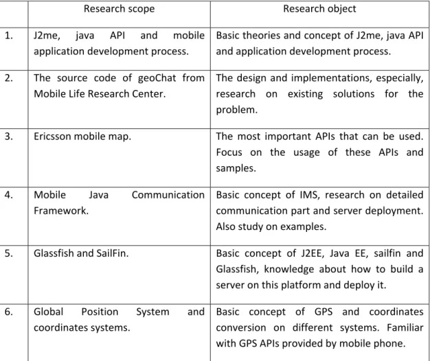
According to the previous problem analysis, Table 1 illustrates the corresponding research
scope and objects
Research scope Research object
1. J2me, java API and mobile
application development process.
Basic theories and concept of J2me, java API
and application development process.
2. The source code of geoChat from
Mobile Life Research Center.
The design and implementations, especially,
research on existing solutions for the
problem.
3. Ericsson mobile map. The most important APIs that can be used.
Focus on the usage of these APIs and
samples.
4. Mobile Java Communication
Framework.
Basic concept of IMS, research on detailed
communication part and server deployment.
Also study on examples.
5. Glassfish and SailFin. Basic concept of J2EE, Java EE, sailfin and
Glassfish, knowledge about how to build a
server on this platform and deploy it.
6. Global Position System and
coordinates systems.
Basic concept of GPS and coordinates
conversion on different systems. Familiar
with GPS APIs provided by mobile phone.
Here, one thing needs to be point out is the second research object – the source code of
geoChat. As mentioned in chapter 1.1, the geoChat is also used as an initial prototype of this
project, research on this object becomes more important and valuable. There were already
some solutions that can solve the problem; so some source code could be reused directly;
and their ideas for solving the problems can also help in similar problem solving.
1.4
Thesis
outline
The whole report consists of five chapters. A brief description of each chapter and its
content is listed as follows:
Chapter 1 introduces the background and the main purpose of this project, with the analysis
of the main problems related to this project. It also lists the research objects and scopes.
Chapter 2 presents the theoretical frameworks related and applied in this project.
Chapter 3 presents the details about system design and development process, for both
client site and server.
Chapter 4 presents the deployment and testing of the application prototype; it introduces
the process of deploying a mobile application on a working mobile phone, and the methods
used in testing the system. Finally, the testing results were presented.
Chapter 5 presents a conclusion and discusses the future works of this project.
2
Theoretical
Framework
This chapter presents the theoretical frameworks that have been studied and applied in the
project development process.
2.1
Java
API
and
micro
edition
In this project, a number of APIs has been used. They are either from Java library provided
by SUN Company or made by companies like Ericsson Labs or even personal generation. ,
Therefore, to understand the basic concept of Java API and how it works was considered as
the primary task of this project.
API (Application Programming Interface) is an interface that defines the ways by which an
application program may request services from libraries and/or operating system. An API
determines the vocabulary and calling conventions the programmer should employ to use
the services. It may include specifications for routines, data structures, object classes and
protocols used to communicate between the requesting software and the library. [1]
An API can be either language‐dependent or ‐independent, Java API is Java language
dependent. From the software perspective, Java API can be considered as a set of Java
classes.
And then, what is Java Micro Edition? The simplest answer is J2ME or it is a special edition of
Java with some differences. Java 2 Micro Edition (J2ME) combines a resource‐constrained
JVM (traditional Java Virtual Machine) and a set of Java APIs for developing applications of
mobile devices. According to the limited memory size and resource availability of mobile
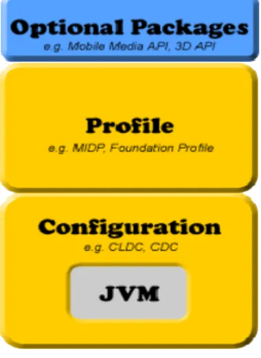
devices, J2ME defines a limited version of the JVM as well [2]. J2ME can be divided into
three parts (as shown in Figure 1): A configuration, a profile, and optional packages. A
configuration contains the JVM (not the traditional JVM, but the cut‐down version) and
some class libraries; a profile builds on top of these base class libraries by providing a useful
set of APIs; optional packages are an optional set of APIs that may or may not be used when
creating applications. Optional packages are traditional and not packaged by the device
manufacturers, they need to be packaged and distributed with the application. The device
Figure 1: The J2ME stack
As shown in figure 1, there are two important elements in J2ME stack – MIDP (Mobile
Information Device Profile) and CLDC (Connected Limited Device Configuration), which are
provided by device manufacturers. The most popular MIDP and CLDC are provided by Sun
Company. CLDC is for devices with limited configurations, for instance, devices with only
around 128KB to 512KB of memory availability for Java applications. Consequently, the JVM
it provides is restricted and only supports a small number of traditional Java classes. (This
limited version of JVM is actually called KVM.) The counterpart of CLDC, called the
Connected Device Configuration (CDC), which is for devices with at least 2MB of memory
availability and supports a more feature‐rich JVM (but still not a standard JVM). The MIDP
complements the CLDC configuration, which minimizes both the memory and power
requirements for devices. It provides the basic APIs used for creating applications. For
instance, it provides the “javax.microedition.lcdui” package, which allows the creation of
GUI elements that can be shown on a limited device running the MIDP on top of a CLDC
configuration [2].
In general, J2ME is a kind of Java edition specially designed for mobile application
development, and it contains two paramount components – CLDL and MIDP. CLDC provides
all the APIs for J2ME development environment, and MIDP provides a special Virtual
Machine for running a J2ME application, and MIDP also provides the configurations of a
mobile device.
2.2
Ericsson
mobile
map
Currently, map is not a new feature that used in mobile field. On today’s market, there are
various kinds of maps available, such as Google maps and Yahoo! maps. Unfortunately, none
Ericsson AB, as the pioneer in mobile area, released their new mobile map API named
Ericsson Mobile Map on 1st April 2009.
Ericsson Mobile Map is a standard J2ME API; it can be simply and easily used on a mobile
device, either directly or used inside any other mobile applications as an import API. In order
to use mobile map, the Java ME or Android library needs to be downloaded, both of them
provides the functionalities of downloading, displaying, and interacting with maps to mobile
applications. It also includes access to the map data itself. Through its unique functionality of
rendering the maps in the mobile phone application, Mobile Maps use very low bandwidth
in comparison to many other map services and applications. It can provide faster running
applications and lower data costs. Rendering the maps in the application also gives more
control and flexibility to developers when developing the applications. And with Mobile
Maps, it is possible to create various kinds of applications such as friend finders, navigation
systems, restaurant locators, weather services; location based social networks etc [3].
After introduced the general information about the mobile maps, the API documentations
were studied [4]. This Map API includes three packages: mmaps, tools and util. Table 2
shows the structure of this API:
Package Class mmap CustomObject PickListener Compnent CustomerLayer CustomSymbol GeoMap Layer MapAnimator MapCanvas MapComponent tools Tool KeyNavigationTool KeyPickCustomObjectTool PoniterNavigationTool ScaleBarTool util EventReceiver Logger ObjectArray
In this API structure table, all the classes in the “mmap” package is a kind of map component
except “MapCanvas” and “GeoMap”. All of these components can be easily used with
mobile map directly; the “MapCanvas” is a standard canvas extends from the “Canvas” class
in Java standard APIs that used to paint a “GeoMap”. And the “mmap” package also
provides two public interfaces – “CustomObject” and “PickListener”, sometimes, those
existing map components might not completely reach the developer’s requirements then
these two interfaces will be easily used to create their own components in that case [5].
Another package – tools, as the name represents, provides different tools that used to
operate on a map. It also provides a public interface. The most powerful and useful tool in
those tools is “KeyNavigationTool”, it has many staple functionalities, such as move to
different locations on a map, zoom in or out, change the angle of view and so on. If the
default tool cannot meet some special requirements, there is also a simple way to customize
a tool by using the public interface “Tool”.
The interesting part in the last package is called “ObjectArray”, which is kind of abstract data
container used to store objects. Essentially, it is a resizable array, it also has some methods
used to operate objects, for instance, add, insert, remove and get an object. In mobile
application development, it is quite useful since there is no such existing abstract data
container provided by J2ME library. Figure 2 represents the relationships between the
classes of the Map API [5].
Figure 2: Class Diagram of Ericsson Mobile Map
After studied Ericsson Mobile Map API documentations, the way that a map works was
further explored. Essentially, to display a map is to paint a map on the screen by a
“MapCanvas”, therefore “MapCanvas” became a movable map viewer that was used to view
different parts of a map via setting the canvas center position to different map location
through a navigation tool. And all the elements displaying on this map are paintable objects
must use a layer as carrier, otherwise they cannot be displayed.
Another important factor of the map is location, which is indicated by coordinates.
Coordinates can present different values and formats in different system, for instance,
Global Position System (GPS) uses the actual value of longitude and latitude, map system
usually use geographic coordinates and displaying system (screen) normally use pixels.
Therefore, there should be an algorithm to convert these coordinates in order to be used in
different systems. Fortunately, Ericsson Mobile Map API provides such functionalities.
Details regarding the coordinates of mobile map will be discussed in the next section.
2.3
Global
Position
System
(GPS)
and
Coordinates
Today, Global Position System (GPS) is no longer a new technology, it has been widely used
in many fields. In this section, the coordinates and the general usage of GPS API that
The GPS presents a location as two numbers, which states the actual values of longitude and
latitude. Latitude is the angle from the center of the Earth to some east‐west line on the
Earth's surface. Longitude is the angle from the center of the Earth to a north‐south line on
the Earth's surface. Latitude and longitude may be expressed as decimal degrees (DD) or as
degrees, minutes, and seconds (DMS); the latter gives numbers in a format such as
49°30'00" S 12°30'00" E. This is the format typically used in GPS devices [7]. Figure 3
shows the Earth overlaid with latitude and longitude lines:
Figure 3: The earth with longitude and latitude lines displayed
The latitude and longitude system is the best‐known way to designate geographic
coordinates which maps using. But it does not mean that the value of the latitude and
longitude could be used on map coordinates system directly because maps use another
coordinates system ‐ Universal Transverse Mercator coordinates system. The UTM
coordinate system is a grid‐based method for specifying coordinates. The UTM system
divides the Earth into 60 zones, each based on the Transverse Mercator projection. Map
projection in cartography is a way to present a two‐dimensional curved surface on a plane,
Figure 4: A Transverse Mercator projection
However, it is not necessary to totally understand the concepts and algorithms for
coordinate’s conversion. To make it simpler, just remember that map has its own
coordinates system and it is differ from GPS’s, GPS using latitude and longitude values
directly but map does not.
At the discussed before, it mentioned that map canvas uses its own coordinates system
other than GPS and Map. It used a standard two dimensions coordinates system – cross
shaft and ordinate axis, and normally they are labeled by X and Y. Moreover, the maximum
value of X and Y actually is the width and length of a canvas and the minimum value should
be greater than zero. Figure 5 shows this coordinates system:
However, this project requires using both GPS and mapping, and the only way to display
map is to use a map canvas. In other words, the coordinate’s conversion problem will be
generated between GPS, map and canvas, and figure 6 clearly states the problem:
Figure 6: Coordinates using between different systems
Location coordinates from GPS system were presented by two float numbers, and these
numbers cannot be used in map directly, as discussed before. The map must have an
algorithm to convert these coordinates. Fortunately, the Ericsson Mobile Map API provides
such a method called “internalValue (double v)” in “GeoMap” class. Map canvas also
requires another kinds of coordinates for displaying the map, and Java standard API does
not provide such functionality, but Ericsson Mobile Map API provides it, within the same
class ‐ “GeoMap”, Methods to convert those coordinates can be found to use them in map
(map system) and canvas (displaying system).
2.4
Glassfish
and
SailFin
At JavaOne 2005, Sun announced Project GlassFish, an open source community comprising
of Users, Developers, Partners, and Evangelists creating an industry leading Java EE 5
compatible enterprise‐quality Application Server [7]. A new concept – Java EE 5 has
appeared. By looking into the phylogeny of Java EE, it is easy to find that Java EE 5 is a later
version of J2EE. They shared one full name – Java platform, enterprise edition. Essentially,
J2EE is a distributed development environment for developing an application server; it is as
There are several sub‐projects under the GlassFish project which used GlassFish as the
runtime. Sailfin is a subproject under GlassFish. Other than GlassFish, Sailfin is based on SIP
Servlet technology. In addition to the SIP Servlet Container, Sailfin also aims to provide High
Availability of the SIP Servlet Container and a load‐balancer for both SIP and HTTP traffic.
Given the functionality, the Sailfin code base requires GlassFish as its underlying runtime.
The Web Container from GlassFish and the SIP Servlet Container becomes the converged
container that is typical of the SIP Application Servers based on JSR289. Figure 7 illustrates a
schematic that explains the relationship between Sailfin and GlassFish [8]:
Figure 7: Sailfin and GlassFish
(SPI = Server Provider Interface)
It is enough to only understand the basic concepts for higher level developer. Details about
how to set up the Java EE, GlassFish and Sailfin environment will be introduced in section 3.2.
Next section will discuss the Java mobile communication framework which is tightly related
to Sailfin.
2.5
Mobile
Java
Communication
Framework
Before start talking about the mobile java communication framework, one thing need be
mentioned is the IMS system, which is based on a 3GPP standard. Ericsson Labs has
deployed a live IMS core network that provides the basic communications between mobile
client and server, such as sending sip message. It also hosts Application Servers (AS) based
on GlassFish/Sailfin, the AS support among other things JSR289 [4], on which the MJCF
server APIs are built, and Glassfish implements all the latest Java EE technologies in addition
to JSR289. Therefore, IMS is able to provide various services especially for mobile
development, but only SIP application server was used in this project, since Session Initiation
Protocol (SIP) is the only protocol using between a mobile terminal and IMS. Figure 8 shows
Figure 8: Mobile java communication framework
The connections from mobile terminals to the MJCF network are made using the data‐
connection. When an IMS application is deployed on the mobile phone and the users starts
the application, a data‐connection from the mobile phone to the SBG will be established.
This connection will traverse the internet/WAP gateway of the mobile operator and possibly
one (or more) NAT/NAPT. Because NAT/NAPT's are used, the connection is using TCP to
maintain the connectivity between the mobile phone and the MJCF network, effectively SBG.
When the connection between the phone and SBG is established, the user (application)
performs a registration to the MJCF core network. SIP Register will be sent to S‐CSCF, which
will perform authentication [9].
It is not necessary to understand the underlying working behind this framework and those
specific terms in this project. The only thing needs to be concerned is how to make the
mobile phone get communicated with IMS, this problem can be solved by using IMS APIs
[10]. The APIs has two versions used on client side and server side, IMS API for client
provides a way allows mobile terminal (usually a mobile phone) connect to IMS via Internet,
and the API for server side permits an application server running on IMS AS and using the
Figure 9: IMS API Components
The IMS layer APIs are divided in two parts: IMS Core API and IMS CoSe API. CoSe stands for
Communication Service. The API provided to MJCF developers includes:
• IMS Core API, the one provided to application developers
• Presence
The abstraction level in the APIs hides the IMS and SIP specifics to the application developer.
A server application could be built by using the IMS Core API, and it can act as a UAC (User
Agent Client), UAS (User Agent Server) or both. An UAC is a logical entity that creates and
sends a new request, whereas UAS is a logical entity that generates a response to a SIP
request.
3
System
development
In this chapter, the whole development process for both client and server side was
described. It started by introducing the methodology used in this software development,
then talked about the development environment setting and development tools selection.
After that, the development process was introduced– from specifying the requirements to
software design and implemented it. During the development process, important
documentations have been generated such as Requirements Specification and System
Sequence Diagram.
3.1
Methodology
Today, in the software development area, various methodologies are available for
developers and some of them are quite famous such as waterfall model. It is quite important
to select the best suitable methodology that can make the development process more
efficiency.
According to the requirements of this project and based on the analysis of different
development models. Finally, the Rapid Prototype Model was selected, for the following
reasons:
One of this project’s objectives is to developing a run‐able prototype, and only
one developer works on this project, so some models are not applicable such as
waterfall model, since they are adaptive for large project. Therefore, some
nimble models are more suitable, for instance, Extreme Program (XP), Build‐and‐
Fix model, Rapid Prototype Model, and Agile development process.
By focused on those quick development models and combined with the main
characteristics of this project – an initial prototype already made by Mobile Life;
Rapid Prototype Model stands out from others.
Another fateful factor of choosing rapid model is time. The whole development
period is only four months including one month for documentation and other
affairs such as comment the source code, report writing, attend meetings,
presentation and demonstration, limited time was available for this project.
Therefore, Rapid Prototype Model or called Rapid software Prototyping process was used. It
describes a practice in software development process or application development process
and sometimes refers to rapid application development (RAD). Rapid Application
Development (RAD) also refers to a type of software development methodology, which uses
minimal planning in favor of rapid prototyping. The "planning" of software developed using
generally allows software to be written much faster, and makes it easier to change
requirements [11].
At the beginning of this project, a minimal plan has been made, all the following works were
strictly based on the plan, even though there are some changes during the development
process. This project is fully supervised by the supervisors from Ericsson Research Luleå, and
periodic meetings and reviews on the progress of this project were held throughout the
project.
3.2
Development
environment
setting
and
tools
To set up the development environment and select development tools is the primary task of
this project. As mentioned before, the aim of this project is to develop a mobile application
using IMS communication. Windows and J2ME environment are needed for client side
development, and on the server side, GlassFish/Sailfin and Java EE 5 environment are
required. Regarding the development tools, a Java IDE, an emulator of mobile phones and
GlassFish/Sailfin plug‐ins for Java IDE are prepared.
Windows is a general environment for mobile application development though it is not the
unique environment for running J2ME. However, there is no mobile phone emulator can be
used without Windows environment. Windows operation system seems to be the only
option. Then, the development environment was set up by the following steps:
1. Using which kind of Java IDE really depends on developer, but Service Development
Studio (SDS) is high recommended. Since SDS is a special development tool for
mobile application that is created by Ericsson AB, it integrated almost everything
needed in mobile application development, it includes: JDK for setting up Java, J2ME
and Java EE environment, Eclipse IDE, Sailfin plug‐in, and so on. All these features
state as a strong reason of using it, it can make the environment setting much
simpler and easier.
2. Installed GlassFish separately after installed SDS, the installation should strictly
follow the instructions provided on its official website.
3. The last thing is to set up an emulator of mobile phones, and currently there are two
emulators provided by SUN or Sony Ericsson. In this project, the emulator from Sony
Ericsson was chosen, since this prototype is developed for Sony Ericsson mobile
phone using, it can ensure a better compatibility. Normally, emulator is
encapsulated into the software application named WTK, and WTK can be easily
downloaded from either SUN or Sony Ericsson’s official website.
Besides the environment setting and tools selection, some APIs are also needed – Ericsson
from Ericsson Labs official website. And for fully use of the functionalities provided by these
APIs, a serial key was required for using the map and a public SIP address for IMS
communication.
3.3
Software
requirements
specification
Requirements specification is the key for a successful project. One research report showed
that more than 50% projects are failed just because of not‐well‐defined requirements
specification. In this project, analysis of both functional and non‐functional requirements
was conducted.
3.3.1 Functional requirements
As mentioned previously in the introduction section, this project already had a prototype
made from Mobile Life Research Center in Stockholm. Therefore, it is easier to start with
functional requirements analysis, which is also a process to re‐specify the requirements. The
analysis results were stated as follows:
The system should provide a map displayed on the mobile phone screen.
The system should provide a navigation tool allows user to do some basic
operations on the map. These operations should at least include moving map to left,
right, up and down, zooming in and out. By using the navigation tool, user can
make selections between different chatting rooms.
The system should request user login and type‐in a unique nickname for chatting, it
means that system can provide a dialog box for login and a check function used to
check if the nickname was taken by others. If the nickname has already been used,
a warning message should be displayed to user.
The system should provide the function to create new chat room where user can
create new chat rooms and locate it anywhere on the map. Before creating chat
room, system should request user to input a chat topic for that room. Once a new
room has been put on the map, it should be re‐sizeable which means while the
user zoomed in or out the map; the room should be resized to larger or smaller
according to its scale with the map. Before user locates a new room, system should
also allow user cancel this action about room creating.
The system should provide text message chatting functionality. Before start
chatting, user should select at least a room to join in. The chatting contents were
shared only inside this room which means the message only send to the user who
selected the same room to chat. After chatting, user was able to leave the room. The system should provide two chat models. User can change between two models
whenever they want. In one model, user can use the navigation tool to select
different chat rooms, whereas in the other model, this tool will be disabled. The
selection can be done only when user located around a chatting room’s in reality.
The user location was traced by GPS.
The system should provide a server for chatting. This server should be responsible
for text message delivering and storage of all chat rooms’ information. 3.3.2 Non‐functional requirements
Normally, there is no clear boundary between functional and non‐functional requirements.
Sometimes it is hard to define which requirement is functional or non‐functional. In this
report, non‐functional requirements were defined from a holistic perspective analysis based
on the project general requirements such as using Ericsson Mobile Map is a non‐functional
requirement. Most of non‐functional requirements contained some of the functional
requirements. For instance, the system must run in a real Java mobile phone is a non‐
functional requirement and it is also a requirement for all of the functional requirements.
The Non‐functional requirements defined in this project were:
The system should be developed as a run‐able prototype in a Java mobile phone. The system should use Ericsson Mobile Map only.
The system should use IMS communication server.
The system should have a consistency mechanism to solve synchronization problem
between clients.
The system should use APIs from Ericsson Research as many as possible.
The system should provide a friendly and steerable Graphic User Interface (GUI). The system should be implemented as a standard API that could be easily and simply
re‐used.
The requirements specification required to be well defined and clearly described, and the
ambiguous of specification should be reduced to minimum. However, this project is a just
small project that only focused on a run‐able prototype, and this prototype only delivered
internal not to end‐customers, the requirements specification did not need to be detailed
described as usual.
3.4
System
design
In this section, the domain class analysis and the use cases that abstracted from the previous
requirements specification were specified. After that, the system sequence behaviors were
described. In the end, the communication protocol design is introduced. Also, some design
diagrams were going to be presented, such as Domain Class Diagram (DCD), Use Case
Diagram (UCD) And System Sequence Diagram (SSD). 3.4.1 Domain class analysis
Based on the project description and requirements specification, the domain class analysis
started with client side instead of server side. Since in this system, server was used just for
The first class needs to be created is a “MIDLet” class, this class was used to start a mobile
application. According to the requirements specification, some main components of this
system can be abstracted, which were: map, chat room and tools. These classes also need to
be created except map. Since map can be used as an object from Ericsson Mobile Map API, it
will not be existed in the system as a class but will be called by system core class. As known
before, it is not possible to display an object on the map directly; the only way is to use a
layer as carrier, so a layer for displaying chat room is also needed.
So far, a map, chat room, tool and chat room layer was created; one more thing was missing
for chatting is message, which should be another class. For displaying all the text content on
the map, a layer was required. Now in the system design phase, the most important classes
were defined and created, but they are probably not enough in the implementation phase.
Therefore, some classes were modified and added in the implementation process. Figure 10
shows the Domain Class Diagram (CD) for the current design phase:
Figure 10: Domain Class Diagram 3.4.2 Abstract Use Cases
Abstracting use cases from the requirements specification should cover the most important
requirements and system’s functionalities. Each of these use cases should be tagged by a
unique serial number. In this case, simple numbers such as 1, 2, 3 and 4 was used:
1. Use Case 1: Login
2. Use Case 2: Create a chat room
3. Use Case 3: Chat in one room
The following Use Case Diagram shows the system boundary and the relationships between
user and use cases:
Figure 11: Use Case Diagram
In this use case diagram, the pane with the label – “Ericsson GeoChat System” indicated the
boundary of this system, and the four ellipses showed the use cases inside this boundary
and occupied some part of system resources, but not all of them. Except those use cases,
the remaining part indicated some other resources of this system, such as communication
part and IMS server. On left‐side of system boundary, the symbols represented user’s part of
this system, and “0…*” means the user quantity can be ranged from zero to infinite.
The following use cases were not fully dressed, only successful system operations were
recorded and the failed operations were ignored: Use case 1: Login
1. The system displays a login dialog asking user to enter a nickname that used for
chatting.
2. User enters a nickname then presses “Login” command key.
3. The system displays a map to user. Use case 2: Create a chatting room
1. User presses “Create” command key.
2. The system displays a dialog asking user to enter a chatting topic.
3. User enters a text topic then presses “ok” command key.
4. The system displays a new chatting room shown as a red square on the screen.
5. User uses a navigation tool provided by system to select a location on the map
where he/she wants to locate the new chatting room.
6. User presses “Put” command key, and the new chatting room is displayed on
the correct location. Use case 3: Chat in a room
2. User presses “Enter” command key to enter the chatting room which was
selected before.
3. The system displays a text area for text message chatting.
4. User enters the message then presses “Send” command key.
5. System displays the message on the text area.
6. User presses “Exit Room” command key.
7. The system displays the map and chatting rooms as before entered. Use case 4: Log‐out
1. User presses “Exit” command key.
2. The system stops displaying the map and exits the system. 3.4.3 System Sequence Diagram
The use case described user actions and system behavior that considered the whole system
as a black box, the details on how the system works were not visible for developer, for
instance, in the use cases 1 – login the system, it looks very simple but actually the system
did not behave that simple, it involved more complex mechanisms. Hence, in this section,
the inside of this black box was explored and the system behaviors were understood by
using System Sequence Diagram (SSD).
The following diagrams represents the system’s behavior step by step which triggered by
actions from user, each of these diagrams was related to the one use case and each step
was classified with a unique serial number. The principle of this numbering was, each step
was identified with a decimal number such as 1.1 or 1.2. The numbers on the left side of the
point (the number 1) indicated a single action, and both 1.1 and 1.2 means these two steps
happened after action 1, and step 1.1 happened before step 1.2. After action 1 completed,
the next step user action will be numbered with 2. The blocks on the lines blowing each class
presented the system consume time for each step. Not all the classes of this system were
shown up in each diagram; it only presented the ones that responsible for the sequence
actions of this use case.
Now, the System Sequence Diagrams will be described one by one. Figure 12 is the System
Sequence Diagram (SSD) of Use Case 1, which explained the system behaviors when user
tried to login the system. In this diagram, from the step 1.0 to 2.0 is system’s initialization
which implemented inside the class “EricssonGeoChat”. It happened before action – login,
Figure 12: System Sequence Diagram of Use Case 1.
The System Sequence Diagram (SSD) of Use Case 2 (Figure 13) presents the system
behaviors when user is creating a new chatting room. In the step 2.2, inside the constructor,
suspension points were used instead of needed parameters, because of the limited space on
the picture.
Figure 13: System Sequence Diagram of Use Case 2
The next SSD corresponding to the Use Case 3 (figure 14) shows how the system behaves as
and then server delivered to all users, so the system did not display the messages directly to
the user who sent it.
Figure 14: System Sequence Diagram of Use Case 3
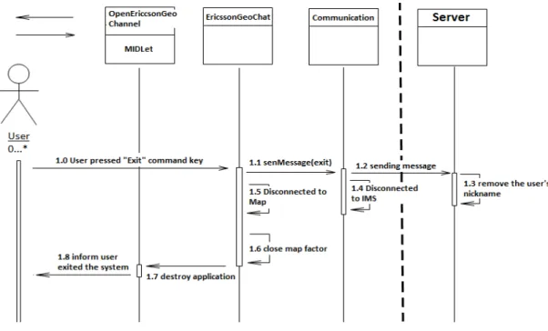
The last diagram is for Use Case 4 – exit the system (Figure 15). The user’s actions in this use
case are quite simple compare to system behaviors. The system did not only close the client
but also informed the server to reactive the current nickname by sending a message, which
means this user’s nickname will be available to others after she/he exited the system.
Figure 15: System Sequence Diagram of Use Case 4
The previous System Sequence Diagrams (SSD) only presents the server as a single class; the
server side has not been designed so far. More details about the communication and
server’s behavior will be described in the next section. 3.4.4 System Communication Design
After introduced the designs on the client side, the design of the system communication was
discussed in this section. To use IMS communication is one of the requirements
Figure 16: System Communication
In this figure, there is no direct communication between clients, all the communications
must go though the server, this solution called centralized control was used to solve the
consistency problems involved in this system. It synchronized the instant updating between
clients by using server to control all the updating requests sending intensively. For instance,
one of these clients created a new chat room; then the room displaying should be updated.
The client only sent the message to server but not executed updating immediately by itself
or sent this updating request to other clients directly. After that, the sever delivered this
updating request as a message to each of these clients including the sender. In that way,
every client can be synchronized at the same time.
Another consistency problem was to keep synchronization between client and server, for
example, when two clients sent updating messages to sever at the same time and the
system should synchronize them. To solve this problem was quite easy since the IMS has
already had a mechanism to synchronize all the messages from different clients by using a
message queue. Details about the solution will not be discussed here, just know there
existed ways to solve this problem.
3.5
Implementation
After system design then the next phase – implementation will be introduced; this section
3.5.1 Implementation on client side
The following paragraphs introduced the implementation on client side. It presented an
overview of the implementation on client side first, and then described the implementations
with focus on the main features of this system.
3.5.1.1 Overview of the implementation on client side
The source code of client side has been implemented into five packages: GUI, Chat, Tool,
Client and Default. Figure 17 shows the content and structure of these packages:
Figure 17: Packages of client
Each of these five packages was briefly described:
The default package contains the most important functional classes and interfaces
of this system. For instance, a MIDLet class – “OpenEricssonGeoChannel” and the
system core class – “EricssonGeoChat” which controlled most of main functionalities
of the system.
The “GUI” package includes two classes that related to the text displaying.
“Chat” package has the classes that implemented the chat function, for instance,
“ChatRommLayer” was used to display all rooms, “ChatRoom” was used to create
object of a chat room and “Message” represented an actual message used while
chatting.
In the “Tool” package, there is only one class provided a tool kit to user.
The last package also has only one class which is responsible for the communication
between client and server.
After that, the system Class Diagram (CD) presented the relationships between these classes
(Figure 18): Client Default • ChattingCore • EricssonGeoChat • OpenEricssonGeoChannel • keycodeMatcher • keycodeListener • Controllable • ControlListener • Utils GUI • TextInputField • Transparency Chat • ChatRoom • ChattingRommLayer • Message Tool • EMMToolKit Client • Communication
Figure 18: Classes Diagram (CD)
As mentioned before, this Class Diagram represented more classes than it did in design
phase. In particular, some interfaces and classes were reused from “GeoChat” source code.
However, the main classes were reserved such as two layers and “ChatRoom”, still,
“EricssonGeoChat” is the core class of this system which is related to each class directly or
indirectly.
3.5.1.2 Map displaying
To display a map on a mobile phone’s screen is the main feature of this system, and the
corresponding implementation is not that complicate. See the figure 19:
In this implementation, the Ericsson Mobile Map API (EMM API) was used directly to display
the map. Based on the research of the EMM API, it is known that the only way to display
map is to paint map by using a canvas, and this API provides all of these elements. On the
top this figure, a MIDLet class was used to start running the system, then it called the core
class – “EricssonGeoChat” to get a map canvas for map displaying, the “EricssonGeoChat”
class used EMM API to request “MapFactory” to create a map canvas and a map.
3.5.1.3 Chat room displaying
Now, the system has displayed a map as background, the next step was to display chat
rooms on the top of the map. The research results stated clearly that to display paintable
elements on a map requires a layer as carrier, which means a layer between map and chat
rooms should be covered, and the chat room must also be draw‐able. Figure 20 shows the
implementation:
Figure 20: Implementation of Chat Room Displaying
As previously discussed, the layer and chat room have to be paintable objects; therefore, the
layer was used to be extended from the class named “CustomLayer” in EMM API, which is a
paintable object. However, the draw method was rewritten to make the layer fully
transparent, and then the layer covered on the map invisibly. In the “ChatRoom”, a draw
method was implemented to make it paintable, it drawn a chat room as either a filled or not
filled red square while it was selected or not. The following screenshots in figure 21 present
the chat room in different selection status. The first screenshot shows an un‐selected chat
room, the second one shows selected room. And the last screenshot shows the menu
implemented in the system, the “Enter” command only works when a chat room was
Figure 21: The System Screenshot on Chatting Room Selection
Another part of chat room displaying is to resize the room. In the requirements specification,
it was clearly described that the size of chat room should be resized while user zoomed in or
out on a map. Here, the size was displaying size but not the actual size of the chat room. To
make displaying size resize‐able actually was to make a dynamic displaying size for each chat
room, it also means that the draw method in ”ChatRoom” class should have an algorithm to
calculate the displaying size dynamically each time when user zoomed in or out on the map.
And to zoom in or out on map essentially was to set different scales on the map. From this
thread, it is easy to find that the displaying size changing was always accompanied by scale
changing. Finally, the following code in figure 22 was implemented:
Figure 22: Source Code for Chat Room Displaying Size
In the example code, there were two variables: “orgScale” indicated the original map scale
when the room was created, and “chatRoomSize” was the initial displaying size when
created. Therefore, when the current map scale was changed, it will affect the displaying
3.5.1.4 Tools
According to the requirements specification, at least three tools were needed in this system.
A navigation tool used to control the displaying views of a map, a selection tool for chat
room selection and the text input tool for typing. And if three tools were used in this system
they cannot be used in parallel, otherwise it would produce some troubles, for example,
assume that the number 4 key was used to zoom in as navigation tool, it also indicated three
letters – “g”, “h” and “i” in text input tool, when user pressed this key to zoom in and the
letter “g”, “h” and “i” will still be displayed without request.
The solution of this problem was to create a tool kit which contained these three tools, and
the tool kit provided a way to switch on/off them. Figure 23 shows the implementation:
Figure 23: Implementation on Tools
The “EMMToolKit” switched on both left side for navigation and selection, and right side for
text input. It used the default navigation tool directly provided by the EMM API and
implemented the “Tool” interface in the EMM API. On the other hand, it reused the text
input function from “GeoChat” source code.
3.5.1.5 Text content displaying
So far, the map displaying, chat room displaying and a tool kit were implemented. So if the
system can display the text, then the client side can start chatting, but there was no
communication with server yet. As previous discussed, the only way to display a paintable
element on the map was to use the layer as carrier. For this reason, text displaying required
a layer. This implementation was quite similar to chat room displaying, the only difference
was to use a translucent layer instead of a complete transparent layer, and the displaying
content from chat room to simple string was also changed. Figure 24 shows the
Figure 24: Implementation of Text Displaying
In this implementation, the text input functionality from the “GeoChat” source code was
reused. The “EMMToolKit” was in charge of the keyboard event listening and setting the
input content to “TextInputField”, then “TransparencyLayer” requested the input content
from “TextinputField” and was responsible for displaying them. The “TextInputField” was a
paintable object for input text displaying, it can be located to different positions on the
screen and the displaying field was resize‐able. In this system, the “TransparencyLayer”
combine with the “TextInputField” was used according to different purposes, for instance, in
Figure 25, the first two screenshots presented the “TransparencyLayer” as a request dialog
but in the last one it changed to a chatting dialog. In these screenshots, the cursor indicated
the position of the text input field, the first two field’s positions and size were the same but
the displaying position of the last field was changed to the screen bottom and its size was
also changed wider.
3.5.1.6 GPS based selection
In addition, this project was implemented into two different versions and the only difference
was to use GPS location based selection instead of a selection tool. The reasons to
implement two versions were that GPS location based selection requires the mobile phone
has the capability to support GPS functionality. Unfortunately, GPS phone were not that
popular yet. In the GPS version, the selection tool was disabled; the only way to select a chat
room was to enter the chat room in reality. Figure 26 shows the implementation of GPS
based location selection:
Figure 26: Implementation of GPS Based Selection
To use GPS, one more class called “GPSPositionRetriever” was created which was used to
get a location provider and also implement “LocationListener” interface provided by
standard GPS API. This class has its own independent thread used to listen to the location
changing and was responsible for checkpoint updating shown on figure 27. Each time when
the location changed, it updated the checkpoint to the current location and called the
Figure 27: The System Screenshot on GPS Model
However, there is a bit trouble on user icon displaying updating which will be introduced in
the section 4.3, and the solution of this problem will be discussed in the last section. Until
now, the most important parts of the implementation on client side have been introduced,
in the next section; the implementation on server side will be discussed. 3.5.2 Implementation on server side
This section introduced the implementation on server side. Firstly, an overview of the
implementation was presented, then the protocols used to communicate between client
side and server side were described. In the end of this section, the main services provided by
this server were introduced with the communications that followed these protocols.
3.5.2.1 Overview of the implementation of server
The main purpose of the server in this project was to centralize the messages for delivering,
and maintain the synchronization between users. The server was implemented to a simple
http server which was extends from the “HttpServlet” class in JAVAX API, and it also
implemented “ImsCoreServiceListener”, “SipServletListener” and “ImsPageMessageListener”
Figure 28: The Implementation of Server
To use the SIP service, the server was identified with a public SIP address by developer which
was different from the SIP address of client, and it was applied from Ericsson Labs website.
3.5.2.2 Protocols
Then, another vital thing in system communication was discussed which was –
communication protocols. The protocols were defined as a simple string, and table 3 shows
the protocols and descriptions for each of them:
Protocol Description 1. game: start, It used to inform the server when client is running. 2. chatroom: (Id, topic, coordinate_X, coordinate_Y, scale,) It used to send all the existing chat rooms information to client for initializing the chat rooms displaying for the first time to run client. 3. login: nickname, When user entered a nickname for chatting then it was sent to server to check it validity, if it can be used then server locked this nickname from using by other users. 4. login: yes, 5. newroom: topic, coordinate_X, coordinate_Y, scale, Once a new chat room created by user, it sent all information about this new room to server. 6. updatetoom: Id, topic, coordinate_X, coordinate_Y, scale, After user sent the new chat room information to server, server returned this message to all the clients to inform them to update the displaying for this new room.
7. chatting: roomId, nickname, message content,
This protocol used to send the chatting message between client and server, and it fit both side of client and server.
Table 3: Communication Protocols
The protocols were the messages used for the communication between client and server,
and each of them was defined as a single string that must end with a”,” (comma). In the
protocol 2, it can be iterated to a lengthiness string that contains many chatting rooms
information. For instance, the string – ”chat room: 1, party, 1203948, 2394872, 29384, 2,
football, 2394726, 2836613, 38462, …”, it presented two chat rooms, and can be iterated as
many as possible but need to follow the protocol.
3.5.2.3 Services of the system application server
In this project, the server only provided some basic services that were abstracted from the
requirements specification. The main functional methods were: “pageMessageRecieved (…)”
and “sendMessage ()” inside the class – “EricssonGeoChatServer”. As the name implied,
“pageMessageRecieved (…)” method was used to handle a received message from client
side, and the “sendMessage ()” was used to send message to client. In the
“pageMessageReceived (…)” method, a sequence if‐statement was used to parse the
message from client, and then call the “senMessage (…)” to send a corresponding callback
message. All the messages must follow the protocol, which was well defined before, and
these messages were sent to their respective public SIP address. These functional methods
provided the following services:
1. Chat room information sending service. When the client application started, it sent a
message as the protocol 1 to server, then the server sent the existing chat room