Large-Scale Distributed Computational Fluid Dynamics
on the Information Power Grid using Globus
S. Barnard
, R. Biswas,
S. Saini, R. Van der Wijngaart,
M. Yarrow
y, L. Zechtzer
NAS Division, NASA Ames Research Center, Moffett Field, CA 94035, U.S.A.
f
barnard,rbiswas,saini,wijngaar,yarrow,lou
g@nas.nasa.gov
I. Foster, O. Larsson
MCS Division, Argonne National Laboratory, Argonne, IL 60439, U.S.A.
ffoster,larsson
g@mcs.anl.gov
Abstract
This paper describes an experiment in which a large-scale scientific application developed for tightly-coupled parallel machines is adapted to the distributed execution environment of the Information Power Grid (IPG). A brief overview of the IPG and a description of the computational fluid dynamics (CFD) algorithm are given. The Globus metacomputing toolkit is used as the enabling device for the geographically-distributed computation. Modifications related to latency hiding and load balancing were required for an efficient implementation of the CFD application in the IPG environment. Performance results on a pair of SGI Origin2000 machines indicate that real scientific applica-tions can be effectively implemented on the IPG; however, a significant amount of continued effort is required to make such an environment useful and accessible to scientists and engineers.
1. Introduction
In one of its Enabling Technologies Goals, NASA has committed to “provide next-generation design tools and ex-perimental aircraft to increase design confidence and cut the development cycle for aircraft in half.” To meet such ambitious goals, a significant improvement is required in NASA’s ability to create, process, understand, store, and communicate data. It is unlikely that conventional ap-proaches to high-performance computing will be able to achieve these lofty objectives. Therefore, NASA is building a nationwide infrastructure called the Information Power Grid (IPG).
Employee of MRJ Technology Solutions. y
Employee of Sterling Software.
The IPG is intended to provide ubiquitous and uniform access, through a convenient interface, to a wide range of computational, communication, data analysis, and storage resources, many of which are specialized and cannot be replicated at all user sites. It involves linking the vast, heterogeneous, and geographically-distributed resources of NASA and its IPG partners to create a scalable, adaptive, and transparent computational environment. The interface will hide details of machine particulars, such as location, size, connectivity, and name, thereby presenting users with a unified virtual machine. A blueprint for this proposed technology is documented in [6].
The IPG can be used to address two major comput-ing requirements. The first involves efficiently orchestrat-ing several technologies to enable distributed human col-laboration and location-independent access to unique re-sources. The goal is to create an integrated environment that allows researchers to solve specific problems quickly. The second requirement is to provide a transparent, widely-distributed, high-performance metacomputing facility to solve extremely large applications that are currently in-tractable on tightly-integrated parallel supercomputers.
The goal of the work reported in this paper is a proof-of-concept demonstration of how IPG technology can be used effectively to tackle a challenging problem in this second area: running a single, large computational fluid dynam-ics (CFD) application in a distributed fashion on separate machines. The virtual distributed computer is viewed as a collection of supernodes, where each supernode is a homo-geneous, tightly-coupled machine.
The Globus project [5] aims to develop a software in-frastructure for computations that integrate geographically-distributed computational and information resources. At present, it is a realistic starting point for the implementa-tion of the IPG. Globus has already been deployed on a
large testbed, called GUSTO, spanning 40 sites and pro-viding 2.5 Tflops of compute power. In this paper, we de-scribe how Globus is used to combine homogeneous but dis-tributed resources (SGI Origin2000 systems at NASA Ames Research Center and at Argonne National Laboratory) to simulate an X-38 Crew Return Vehicle (CRV). This experi-ment provided experience with Globus and insights into the requirements for future IPG technology at NASA.
The CFD application chosen for this experiment involves the accurate prediction of high-speed viscous flow around a geometrically-complex three-dimensional body. Problems of this nature challenge the capabilities of the most ad-vanced single-processor platforms available. Large-scale multiprocessor computer systems offer a powerful tool to solve large and complex problems; but they may still not suffice, and gaining exclusive access to them is difficult in practice. The CFD software used is an enhanced version of OVERFLOW [2], the most widely-used flow solver soft-ware at NASA Ames. OVERFLOW deals with the geomet-rical complexity of flow solution domains by allowing sets of separately generated and updated structured discretiza-tion grids to exchange informadiscretiza-tion through interpoladiscretiza-tion.
The main technical challenge in implementing scientific applications on the IPG lies in accommodating the sizable and variable latencies as well as the reduced bandwidths incurred in distributed computations on geographically-separated machines. Common latency-hiding techniques such as pipelining can only be used when data dependencies are known in advance and when data can be prepared and sent long before it is needed. For example, real-time visu-alization of scientific data can be formulated as a two-stage pipeline, with one machine generating the data and the other performing the rendering. But such strategies are useless for running tightly-coupled applications like OVERFLOW in a distributed manner, where computation and communi-cation are intrinsically interleaved. The focus of this work is on identifying and implementing the minimum changes to a state-of-the-art parallel program that are necessary to run it efficiently as a distributed application in an IPG environ-ment.
The remainder of this paper includes a brief overview of the IPG concept and the enabling software layer (Globus) used in this project (Sec. 2), a description of the CFD scheme and an outline of the application used for our exper-iments (Sec. 3), a description of the IPG implementation of the application and computational results (Sec. 4), and sum-mary remarks and a discussion of future directions (Sec. 5).
2. Distributed computing environment
One of the early success stories in the history of dis-tributed computing has been the Parallel Virtual Machine (PVM) [7] library. However, the subsequent substantial use
of PVM also revealed some of the limitations of the concept of the library. Much of the burden of using it for distributed computing fell on the user. For example:
All remote computer resources had to be named within the application program.
All information needed for creating and running remote processes (executables, data files, scripts, etc.) had to be moved to the proper location by the user.
All remote processor and file system access issues, most notably security and accounting, had to be explicitly re-solved by the user.
This led to the realization that a more top-down approach to distributed computing is needed, in which an integrated environment for distributed applications and remote ser-vices is provided without requiring an undue amount of ef-fort on the part of individual users. This quest for an inte-grated but distributed environment forms a substantial pillar of the IPG project.
2.1. Information Power Grid
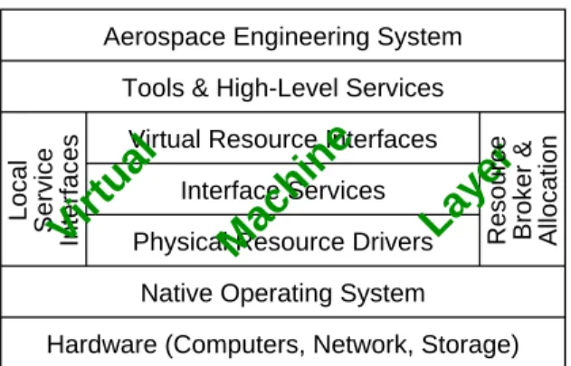
The Information Power Grid (IPG) project is being con-ducted by NASA in collaboration with a number of gov-ernment and academic partners. A large number of com-pute and data resources are currently available in principle to NASA researchers, but they are often not easily acces-sible from different locations. The goal of the IPG is to make these resources available easily, uniformly, and trans-parently. The IPG is intended to facilitate the aggregation of these distributed resources to enable scalable systems re-quired to solve problems that are intractable on current lo-calized computing environments [10]. More specifically, the IPG is meant to support aerospace research and engi-neering, with their typical requirements of large-scale simu-lations and very data- and compute-intensive visualizations. A layered design of IPG, depicted in Fig. 1, makes the technical implementation manageable. The bottom two lay-ers constitute the existing NASA computing environment, and consist of the native operating system and the basic hardware. The top layer, called Aerospace Engineering System, provides a number of tools and interfaces that are specific to future research in aerospace engineering. The Tools and High-Level Services layer provides supplemen-tal tools and interfaces to make the IPG Virtual Machine more user-friendly and easier to administer and maintain. All these four layers are beyond the scope of this paper.
The long-term objectives of the research effort behind this paper is to investigate, develop, and demonstrate tech-nology for the IPG Virtual Machine layer. This layer pro-vides a uniform interface for the user to specify computa-tional or informacomputa-tional tasks, regardless of where the tasks are to be executed. It consists of five separate subsystems, as shown in Fig. 1. This layer constitutes a virtual
dis-Virtual Resource Interfaces
Physical Resource Drivers
Interfaces Interface Services Allocation Service Local
Layer
Machine
Virtual
Resource Broker &Hardware (Computers, Network, Storage) Native Operating System
Tools & High-Level Services Aerospace Engineering System
Figure 1. Layered structure of the Information Power Grid.
tributed computing resource that resolves issues of compati-bility between the heterogeneous systems spread around the organizations of NASA and its partners. This requires tools for specifying memory requirements, the number of dis-tributed processes, processing speeds, compilers, wall clock time needs, libraries, header files, and so on.
2.2. Globus metacomputing toolkit
Several recent research projects [1, 5, 8, 15] provide pro-totypes for the IPG Virtual Machine layer. In this paper we test one of them, the Globus metacomputing toolkit [5], as a possible realization. Globus evolved out of the suc-cessful but still somewhat ad hoc I-WAY high-performance distributed computing experiment [4].
Globus provides core services required for the IPG Vir-tual Machine, including the management of resource lo-cation and allolo-cation, communilo-cation, gathering unified resource information, authentication, remote process cre-ation, fault detection, and remote data access. For the pur-pose of the experiments reported in this paper, in which ded-icated resources are used, the critical Globus components are communication and process creation. Communication is implemented through MPICH-G [3], a Globus-enabled device for the public-domain implementation of MPI [9], and process creation through the co-allocation service ac-cessed via theglobusrun utility used to interface with local schedulers. While Globus is used to make the two remote parallel computers recognize each other, the entire application is run as a single message-passing program un-der MPICH, and the application programmer need not be aware of any distinction between the two machines.
3. Computational fluid dynamics application
The CFD scheme used in this work utilizes structured overset grids based on the Chimera [14] style of domain
decomposition. Such schemes have proven to be appropri-ate for predicting high-speed viscous flows around complex shapes for both static and dynamic (i.e., moving-body) con-figurations. The Chimera scheme divides the entire prob-lem domain into a system of grids that overlap one an-other by one or more grid cells. The solution proceeds by updating, at each iteration, the inter-grid boundaries on each grid with interpolated data from overlapping grids. Geometrically-complex shapes are broken into groups of overlapping curvilinear body-fitted grids and relatively sim-ple rectilinear background grids. Besides being numeri-cally expedient, the domain decomposition nature of the Chimera approach offers a high degree of coarse-grained parallelism that can be exploited in distributed computing environments.
The most popular overset-grid flow solver that is used at NASA Ames Research Center is the OVERFLOW code [2]. There are at least three different parallel implementations of OVERFLOW, using different programming models and data-distribution methods. The first is a fine-grained MPI version where it is possible to partition individual grids among processors; however, it does not have all the vari-ous boundary conditions and grid types implemented. The second version is an MLP (multi-level programming) code designed specifically for the CC-NUMA architecture of the Origin2000. It is able to balance the processor workloads automatically based on runtimes from the first few itera-tions, but does not work on multiple loosely-coupled ma-chines.
The third version is the one used for the experiments re-ported in this paper. Here, each grid is assigned to a unique processor, and the set of grids assigned to any particular processor is referred to as a group. In this coarse-grained data-distribution scheme, it is only necessary to communi-cate some of the boundary information between processors. The computation for individual grids is entirely serial.
A number of enhancements have been made within this third version of OVERFLOW that allow solution-based mesh adaptation [12] and scalable parallel execution [16]. MPI message passing facilitates execution on a variety of distributed computer platforms, and the code has been suc-cessfully tested for static geometry problems on an IBM SP multiprocessor.
3.1. Parallel implementation
Overset grid schemes belong to the general class of Schwarz domain decomposition methods. Since each sub-domain boundary is updated only once per iteration with in-terpolations from neighboring subdomains possibly requir-ing communications, a natural coarse-grained level of par-allelism exists. The automated Cartesian grid generation scheme generates a relatively large number of grids, usually
many more than the available number of processors. This trend is expected to continue as computational problems be-come larger and more complex.
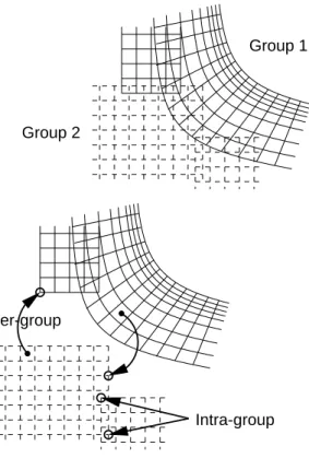
Because there are many more grids than processors, our distribution approach places one or more grids onto each processor in a load-balanced fashion. A grouping algorithm seeks to balance the computational workload by considering both the number of grid points in each group and an estimate of the work associated with each grid point. The latter is necessary because some grids may require more computa-tional work per grid point than those in others. For example, a turbulence model may be applied on grids near the body but not on grids in the far field. Weighting factors that cor-respond to the additional work are applied to the grids con-taining the more computationally intensive points, prior to performing the grouping. The grouping strategy also seeks to maintain a degree of locality among the member grids in each group to maximize the level of intra-group connectiv-ity. Details of the bin-packing grouping algorithm are given in [16].
Group 2
Group 1
Inter-group
Intra-group
Figure 2. Intra-group and inter-group interpo-lations between grids.
Boundary information is interpolated between overlap-ping grids at each iteration. Grids that are in the same group perform intra-group interpolations locally on each proces-sor. Grids that overlap with other grids in a different group perform inter-group interpolations between processors. For
the latter case, the donor values supplied to the neighboring group are computed locally and then exchanged using MPI calls. This approach is outlined schematically in Fig. 2, where two groups are shown, each containing two grids. Both intra-group and inter-group interpolations take place at the end of each iteration; hence, interpolated data on all grids lag by one iteration.
The rectilinear-grid generator occasionally generates grids that are individually much larger than the average size of a group. This situation leads to either load imbalance or to grids that do not fit in core. To avoid this situation, the grids are checked after generation, and a recursive bi-nary splitting technique [16] is applied to those grids that exceed the average group size. The rectilinear-grid gener-ator then automatically generates the appropriate system of grid components and computes the necessary interpolation stencils. The splitting procedure is significantly more com-plicated for the body-fitted curvilinear grids and has not yet been implemented for such grids.
3.2. Test case
The parallel version of the overset CFD code has been implemented on the IBM SP at Army Corps of Engineers Waterways Experiments Station (CEWES). Test cases in-clude steady-state viscous calculations of two relatively complex aerodynamic configurations: NASA’s X-38 Crew Return Vehicle (CRV) and Army’s Comanche helicopter (without blades). The former, shown in Fig. 3, is used for the IPG simulation experiments reported in this paper.
Figure 3. View of the X-38 Crew Return Vehi-cle.
The grid system for the X-38 CRV consists of 13 near-body curvilinear grids and 115 off-near-body rectilinear grids, for a total of more than 2.5 million points. The largest grid is body-fitted, and contains 437,976 points. A single grid this large causes scalability problems; future work will ad-dress this issue. The smallest of the 128 overlapping grids contains only 216 points. Having many small grids is
desir-able from a load balancing perspective, but may harm the convergence of the numerical scheme.
Parallel performance results on a single supercomputer are available in [16]. Runs on up to nine processors of the IBM SP show a total communication cost of only 2% of the entire calculation. The deterioration of the parallel effi-ciency to 88% when going from four (the smallest number of processors required to do in-core computation) to nine processors is due mostly to a poorer load balance as the number of grids per processor decreases. This can be alle-viated to some extent by breaking large grids into several smaller ones.
4. IPG implementation
As mentioned in Sec. 3, the enhanced version of OVER-FLOW has been developed as a coarse-grained parallel pro-gram for tightly-coupled parallel machines. The commu-nication overhead on a fairly richly-connected architecture such as the IBM SP is typically about 10% of the total ex-ecution time on 128 processors. However, in a truly dis-tributed IPG environment with poorer connectivity (smaller aggregate bandwidth) and significantly larger latencies due to the geographical separation of the computers used, mod-ifications must be made to reduce the impact of communi-cation. This is achieved in two phases.
First and most notably, a higher level of asynchrony must be embedded into the numerical scheme to hide latency. This issue is addressed in Sec. 4.1. Second, a more sophisti-cated technique must be used to map the overset grids to the supernodes of the IPG and, in turn, to the individual proces-sors of these supernodes. This is described in Sec. 4.2.
4.1. Latency hiding
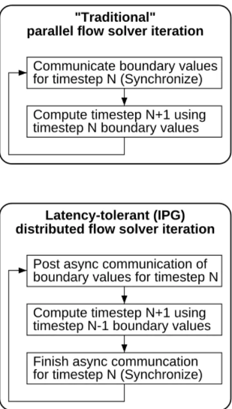
The time-advancement strategy of the solution scheme on the overlapping grids has been altered to hide the in-creased latency between IPG supernodes. In the origi-nal parallel scheme, all communicating processors first ex-change boundary values. Once the exex-change is completed, the interior solution domains are updated independently. Consequently, the entire communication is exposed, and overall performance deteriorates as the connectivity de-grades. In the new scheme, latency tolerance is obtained by lagging the boundary value update by one additional timestep. The boundary value exchange is initiated at the beginning of a timestep, but the values are not used until the beginning of the next timestep. It allows the overlap of com-putation and communication for as much as the duration of one entire timestep. We call this the deferred scheme. Both the original and the deferred schemes are depicted schemat-ically in Fig. 4.
Communicate boundary values
for timestep N (Synchronize) boundary values for timestep N
timestep N-1 boundary values timestep N boundary values
parallel flow solver iteration
Latency-tolerant (IPG) "Traditional"
Finish async communcation Compute timestep N+1 using Post async communication of
distributed flow solver iteration
Compute timestep N+1 using for timestep N (Synchronize)
Figure 4. Creating flow solver latency toler-ance for the IPG environment.
One potential problem with the deferred scheme is that lagging the boundary value updates may render the flow solver unstable or cause it to converge less rapidly. How-ever, the results reported in Sec. 4.3 show negligible dif-ference in convergence or in the values of some physical quantities for the X-38 CRV simulation (which is basically a steady-state case except for some unsteadiness behind the vehicle that does not affect the solution at the leading edge or on the body).
The possibility remains that the deferred method may lead to instability or slower convergence for more difficult unsteady problems. However, note that it is only necessary to use the latency-tolerant method at the boundary between the supernodes, where the high latencies are encountered. It may be possible to partition the collection of grids between the supernodes so that the boundary encompasses only a rel-atively steady, slow-changing part of the solution, thereby avoiding instability or convergence problems.
4.2. Load balancing
The original method for grouping grids and assigning groups to processors described in Sec. 3.1 is ad hoc, but quite effective at balancing load on a tightly-coupled par-allel system for moderate-sized problems (assuming that a
good load balance is possible for a given grid system and number of processors). It mostly ignores the cost of com-munication between grids, except to the extent that it at-tempts to place neighboring grids on the same processor. As long as the communication overhead is relatively insignifi-cant, this will be effective. On a system consisting of two or more loosely-coupled supernodes, however, the greatly increased latency and reduced bandwidth between the su-pernodes can have a substantial impact. Moreover, since large numbers of processors will be required for future very large-scale computations, we are led to investigate a more principled method for load balancing.
The problem of assigning grids to processors in a way that balances load and minimizes communication is a clas-sic partitioning problem, which often arises in distributed unstructured applications. Such a mapping mitigates the ef-fect of reduced bandwidth. The set of grids defines an undi-rected graph, with the grids represented by the vertices and the overlap between pairs of grids represented by the edges. An estimate of the work required by each grid can be used to define a weight for each vertex, and an estimate of the cost of each inter-grid interpolation can be used to define a weight for each edge.
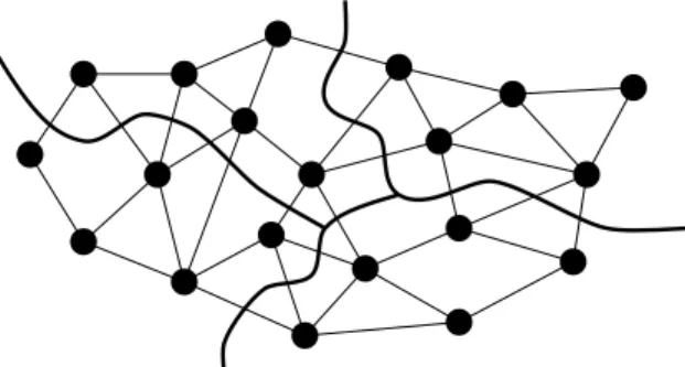
The partitioning problem is to assignvvertices toP pro-cessors (P v) such that each processor has a (roughly) equal aggregate vertex weight, while the total weight of the edges that span different processors is minimized. (Figure 5 shows a small example forv=20andP=4with uniform vertex weights and edge weights). This problem has been thoroughly studied. While it is NP-hard, several heuristic solutions are very effective. We have integrated one such partitioner, called MeTiS [11], into our flow solver code, and find that it distributes grids as effectively as the original scheme. This is because the X-38 CRV test case contains a few very large grids that dominate the workload. It is there-fore impossible to improve the quality of the load balance without splitting the large grids. However, the MeTiS par-titioner will generally be more useful for larger problems with more grids.
Another weakness of the original load balancing method is that it estimates the work required by each grid from the number of grid points. (Near-body grids are treated slightly differently from off-body grids.) While the number of floating-point operations is proportional to the number of grid points, cache effects may introduce nonlinearities be-cause the grid size may interact with the various cache sizes in unpredictable ways. A comparison of the estimated work and the actual work required for each of the 128 grids of the X-38 CRV revealed considerable discrepancies: as high as 13% for one body-fitted grid and 35% for one off-body grid. Instead of using mere estimates for grid weights, we use actual measurements. Using a default partitioning, the simulation is run for a few timesteps and the work for each
Figure 5. Partitioning an unstructured graph while balancing computation and minimizing communication.
grid is measured. These measurements are then used to pro-duce a final partitioning.
4.3. Results
Our IPG testbed consisted of three separate SGI Ori-gin2000 machines: two located at NASA Ames Research Center and the third at Argonne National Laboratory. A maximum of 8 processors were used on any one machine, each running Globus version 1.0.0. MPICH-G was used as the message-passing library.
The flight test conditions for the X-38 CRV were a Mach number of 1.5 and a 15-degree angle of attack. Figure 6 shows the computed Mach contours on the symmetry plane. Additional details of the simulation and computed loads are given in [12].
Figure 6. Mach contours for the X-38 Crew Return Vehicle.
The first experiment was to compare the results of com-putations using the original and deferred versions of the
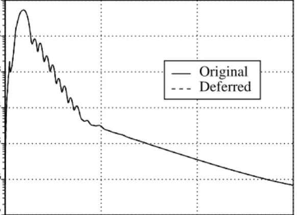
flow solver (as described in Sec. 4.1) for the X-38 configu-ration. Figures 7 and 8 show the difference in theL
2 -norms of the residuals of the iterative scheme for two represen-tative near-body grids. Reduction of the residual on these grids is a good measure of the overall convergence of the method. 0 500 1000 1500 Timestep -7 -6 -5 -4 -3 -2 -1 10 10 10 10 10 10 10 L2-norm Original Deferred
Figure 7. Residual comparison for the X-38 CRV nose cone (grid 1).
0 500 1000 1500 Timestep 0.00 0.01 0.02 0.03 0.04 0.05 L2-norm Original Deferred
Figure 8. Residual comparison for the X-38 CRV rear section (grid 5).
Clearly, there is no discernible difference in convergence between the two versions of the flow solver for grid 1, which is situated at the nose cone of the vehicle. The residual on grid 5, which is situated at the rear of the vehicle, con-verges for neither method. This is due to the fact that the flow in this portion of the configuration is genuinely un-steady, and no steady state (zero residual) exists. Although a mismatch exists between the residual evolutions of the two
schemes, the general trend is similar, and there is no rea-son to believe that the deferred version will be less stable than the original version. The mismatch can be removed by employing a subiteration strategy [13], which is a form of defect correction that is often used to reduce errors due to factorization and poor linearization. However, several random checks of some integrated physical quantities (lift, drag, roll, pitch) for the X-38 from both the original and the deferred time-advancement strategies show differences of only a few tenths of a percent for all cases. Most likely, these differences are caused by the unsteady behavior be-hind the tail. Hence, it is not necessary to incur the addi-tional cost of subiterations.
Having established that the deferred timestep method gives accurate results, we now turn our attention to its ef-ficiency. Table 1 lists the runtime per timestep for three different configurations of eight processors. Evelyn and Piglet are each 8-processor Origin2000 systems located at NASA Ames, connected via a HIPPI channel. Denali is a 96-processor Origin2000 at Argonne, connected to Evelyn and Piglet via a DS3 Internet connection. To eliminate vari-ability, all timings are the minimum over at least 15 trials.
# Processors secs/timestep Evelyn Piglet Denali Original Deferred
4 4 16.2 12.7
8 18.0
4 4 21.4 21.3
Table 1. Wall clock time (in secs) for each timestep of the CFD solver using the original and the deferred methods for three different configurations.
The first row of Table 1 shows that the deferred method does indeed hide at least some of the communication time between two supernodes connected by a rather high-performance HIPPI channel. The second row shows that the application actually runs slower on a single 8-processor supernode than it does on two HIPPI-connected 4-processor supernodes (no difference between the original and the de-ferred methods). This is explained by the fact that the Ori-gin2000 hardware does not support asynchronous message passing, but there are separate DMA engines on the HIPPI boards that do support asynchronous communication be-tween separate systems.
Finally, the third row shows no significant difference be-tween the original and the deferred methods using the Inter-net connection. This result is expected because this config-uration does not allow asynchronous messaging. To over-come this problem, we are currently investigating the use
of dedicated nodes to serve as communication processors. This row of data is included only to show the degradation in performance due to the relatively low-performance Internet connection.
5. Summary and future directions
This paper described an experiment in which a large-scale application in computational fluid dynamics (CFD) was adapted for efficient execution on the distributed envi-ronment of the Information Power Grid (IPG). The Globus metacomputing toolkit was used as the enabling software in this project. The CFD scheme uses structured overset grids and an enhanced version of the OVERFLOW code. The MPI-based OVERFLOW/Chimera application appears to be well-suited for a proof-of-concept demonstration of IPG/Globus technology. The application is very important to NASA, and will soon require resources exceeding what is available in any one tightly-coupled parallel system oper-ated by NASA or its partners.
Load imbalance and communication overhead (given the smaller bandwidth and the larger latency due to the ge-ographical separation of the computational resources used) were identified as the main sources of parallel inefficiency. We anticipate alleviating the load imbalance problem by incorporating a “breakup” scheme to split large near-body grids, through better measurement of the loads associated with each grid, and by using a graph partitioner to more effectively assign grids to processors. Preliminary results showing that the application tolerates an additional lag of one timestep in boundary value interpolation suggests that the extra latency and reduced bandwidth involved in geographically-remote communication can be at least partially hidden. However, significant effort is still required to make the IPG a generally useful and a widely accessible environment for solving major computational problems.
Acknowledgements
The authors gratefully acknowledge the assistance of Andrew Wissink of MCAT, Inc., and Robert Meakin of Army/NASA AFDD for making the adaptive rectilinear-grid version of OVERFLOW available to us for the IPG ex-periments. The authors would also like to thank Terrence McGuinness of San Diego State University for helping us examine the communication capabilities of our Origin2000 computers. This work was partially supported by NASA un-der Contract Number NAS 2-14303 with MRJ Technology Solutions and under Contract Number NAS 2-13619 with Sterling Software.
References
[1] D. Bhatia, V. Burzevski, M. Camuseva, G. Fox, W. Furman-ski, and G. Premchandran. Webflow - a visual programming paradigm for Web/Java based coarse grain distributed com-puting. Concurrency: Practice and Experience, 9:555–577, 1997.
[2] P. Buning, W. Chan, K. Renze, D. Sondak, I.-T. Chiu, J. Slot-nick, R. Gomez, and D. Jespersen. Overflow user’s manual, version 1.6au. NASA Ames Research Center, 1995. [3] I. Foster, J. Geisler, W. Gropp, N. Karonis, E. Lusk,
G. Thiruvathukal, and S. Tuecke. Wide-area implementa-tion of the Message Passing Interface. Parallel Computing, 24:1735–1749, 1998.
[4] I. Foster, J. Geisler, W. Nickless, W. Smith, and S. Tuecke. Software infrastructure for the I-WAY high performance dis-tributed computing experiment. In 5th IEEE Symp. on High
Performance Distributed Computing, pages 562–571, 1997.
[5] I. Foster and C. Kesselman. Globus: A metacomputing in-frastructure toolkit. International Journal of Supercomputer
Applications, 11:115–128, 1997.
[6] I. Foster and C. Kesselman, editors. The Grid: Blueprint for
a New Computing Infrastructure. Morgan Kaufmann, 1999.
[7] A. Geist, A. Beguelin, J. Dongarra, W. Jiang, R. Manchek, and V. Sunderam. PVM: Parallel Virtual Machine. MIT Press, 1994.
[8] A. Grimshaw, W. Wulf, and the Legion team. The Legion vision of a worldwide virtual computer. Communcations of
the ACM, 40:39–45, 1997.
[9] W. Gropp, E. Lusk, N. Doss, and A. Skjellum. A high-performance, portable implementation of the MPI Message Passing Interface Standard. Parallel Computing, 22:789– 828, 1996.
[10] W. Johnston, D. Gannon, W. Nitzberg, and W. V. Dalsem. Information Power Grid implementation plan. Working Draft, NASA Ames Research Center, 1998.
[11] G. Karypis and V. Kumar. A fast and high quality multi-level scheme for partitioning irregular graphs. Department of Computer Science Tech. Rep. 95-035, University of Min-nesota, 1995.
[12] R. Meakin. On adaptive refinement and overset structured grids. In 13th AIAA Computational Fluid Dynamics Conf., AIAA-97-1858, 1997.
[13] T. Pulliam. Time accuracy and the use of implicit methods. In 11th AIAA Computational Fluid Dynamics Conf., AIAA-93-3360, 1993.
[14] J. Steger, F. Dougherty, and J. Benek. A Chimera grid scheme. ASME FED, 5, 1983.
[15] J. Waldo. Jini architecture overview. Sun Microsystems, 1998; http://java.sun.com/products/jini/whitepapers. [16] A. Wissink and R. Meakin. Computational fluid dynamics
with adaptive overset grids on parallel and distributed com-puter platforms. In Intl. Conf. on Parallel and Distributed
Processing Techniques and Applications, pages 1628–1634,