This may be the author’s version of a work that was submitted/accepted
for publication in the following source:
Vilathgamuwa, Don
, Jayasinghe, S.D., Lee, F, & Madawala, Udaya
(2011)
A unique battery/supercapacitor direct integration scheme for hybrid
elec-tric vehicles.
In Chang, E & Ibrahim, Y (Eds.)
Proceedings of the 37th Annual
Confer-ence of the IEEE Industrial Electronics Society.
IEEE, United States of America, pp. 3020-3025.
This file was downloaded from:
https://eprints.qut.edu.au/74898/
c
Consult author(s) regarding copyright matters
This work is covered by copyright. Unless the document is being made available under a Creative Commons Licence, you must assume that re-use is limited to personal use and that permission from the copyright owner must be obtained for all other uses. If the docu-ment is available under a Creative Commons License (or other specified license) then refer to the Licence for details of permitted re-use. It is a condition of access that users recog-nise and abide by the legal requirements associated with these rights. If you believe that this work infringes copyright please provide details by email to [email protected]
Notice
:
Please note that this document may not be the Version of Record
(i.e. published version) of the work. Author manuscript versions (as
Sub-mitted for peer review or as Accepted for publication after peer review) can
be identified by an absence of publisher branding and/or typeset
appear-ance. If there is any doubt, please refer to the published source.
A Unique Battery/Supercapacitor Direct Integration
Scheme for Hybrid Electric Vehicles
D.M. Vilathgamuwa
1,
Senior Member
,
IEEE
, S.D.G. Jayasinghe
1,
Student Member
,
IEEE
, F.C. Lee
1,
U.K. Madawala
2,
Senior Member
,
IEEE
1School of Electrical & Electronic Engineering, Nanyang Technological University, Singapore 2Department of Electrical & Computer Engineering, The University of Auckland, Auckland, New Zealand E-mail: [email protected], [email protected], [email protected], [email protected] Abstract-Battery/supercapacitor hybrid energy storage systems
have been gaining popularity in electric vehicles due to their excellent power and energy performances. Conventional designs of such systems require interfacing dc-dc converters. These additional dc-dc converters increase power loss, complexity, weight and cost. Therefore, this paper proposes a new direct integration scheme for battery/supercapacitor hybrid energy storage systems using a double ended inverter system. This unique approach eliminates the need for interfacing converters and thus it is free from aforementioned drawbacks. Furthermore, the proposed system offers seven operating modes to improve the effective use of available energy in a typical drive cycle of a hybrid electric vehicle. Simulation results are presented to verify the efficacy of the proposed system and control techniques.
Index Terms-Dual inverter, energy storage system interfacing, hybrid electric vehicles.
I. INTRODUCTION
Electric vehicles (EV) have been gaining unprecedented attention mainly due to the facts that our planet is on the brink of having its fossil fuel depleted and there are overwhelming concerns on pollution due to road transport. Notwithstanding such grave concerns, there are still some well known technical issues of EVs such as battery cost and the limited drive range that limit their widespread adoption. Therefore, certain EV technologies are still being developed and more time and research are needed to conquer the market effectively [1]. This has created a technology gap in the transportation sector. Hybrid electric vehicles (HEV) have been emerged as the promising solution to fill the gap. In HEVs, internal combustion engine (ICE) is used as the primary source of power. Peak power required for acceleration is supplied by the combination of ICE and energy storage system. During decelerations, regenerative braking is used to recover part of the kinetic energy of the vehicle. Therefore, HEVs are more efficient and environmental friendly compared to conventional ICE based vehicles.
However, the fuel economy and all-electric range of HEVs are highly dependent on the performance of onboard energy-storage system (ESS) of the vehicle [2]. The combination of battery and supercapacitor is considered as an excellent match that can cover a wide range of power and energy requirements [3]. In such systems supercapacitor relieves the high-energy-density battery unit from peak power transfer
stresses due to its higher specific power and efficiency. This helps to reduce the required battery size. Moreover, the battery life span gets extended due to the suppression of high discharging currents [4]–[10].
The conventional method of interfacing batteries and supercapacitors is the use of two separate bidirectional dc–dc converters [7][15]. Terminal voltage variations of the battery and the supercapacitor are effectively decoupled by interfacing dc-dc converters and hence the voltage across the motor drive dc-link remains constant. However, these interfacing converters introduce considerable switching and conduction power losses. It also poses stability issues, particularly at high inrush currents. Furthermore, interfacing converters add cost and weight to the system, particularly with their large inductors rated for the peak power transfer [8]. Therefore, the trend is to reduce the number of dc-dc converters used in the system.
One such design is the direct connection of the battery into the dc-link of the motor drive. But it suffers from several drawbacks such as, increased cell count and hence large internal resistance, lack of control over battery power flow and fixed current distribution governed by internal resistors of the battery [3][9]. An alternative method is proposed in [3] where the supercapacitor is directly connected to the dc-link and the battery through a dc-dc converter. Even though this design removes one dc-dc converter it limits the supercapacitor voltage discharge ratio to 50% and hence it is underutilized. Passive paralleling to the dc-link is the simplest way to combine a battery and a supercapacitor and eliminate aforementioned drawbacks of dc-dc converters [10]. But in this topology supercapacitor voltage is strictly limited to the battery voltage and thus it is severely underutilized.
Therefore, authors researched on a possible direct connection scheme which can remove both interfacing dc-dc converters while maintaining the same control flexibility exists in such dc-dc converter topologies. The result is the double ended inverter system shown in Fig. 1. In this system, a battery and a supercapacitor bank are directly connected across dc-link capacitors of the auxiliary inverter. This unique approach eliminates the need for interfacing dc-dc converters and thus it is free from aforementioned drawbacks. Standard two-level inverter modules and three-level diode-clamped inverter modules are readily available in the market and therefore this topology does not need complicated assembly. Furthermore, the proposed system offers seven operating modes to improve the effective use of available energy.
Fig. 1. Schematic of the proposed battery/supercapacitor direct integration scheme.
II. OPERATING PRINCIPLE
In order to avoid confusion with the cascaded H-bridge topology and the dual inverter topology, the direct connection scheme in Fig. 1 will hereafter be referred to as double-ended inverter. Voltages at nodes a1, b1 and c1 can be derived from the switching states of the main inverter using (1). Similarly, voltages at nodes a2, b2 and c2 can be derived from the switching states of the auxiliary inverter using (2). Since the two inverters are powered by isolated dc-sources, the two grounds can be considered as independent nodes in the circuit. As a result, zero sequence current does not exist in the proposed system and hence motor phase voltages and currents hold the relationships in (3) and (4). Therefore, an expression can be derived for motor phase voltages as in (5).
[
]
[
]
T cM bM aM dc T g c g b g av
v
V
S
S
S
v
11 11 11=
(1)(
S
aMS
bMS
cM) { }
=
0
,
1
(
)
(
)
(
)
(
)
(
)
(
)
⎥
⎦
⎤
⎢
⎣
⎡
−
⎥
⎥
⎥
⎦
⎤
⎢
⎢
⎢
⎣
⎡
−
−
−
−
−
−
=
⎥
⎥
⎥
⎦
⎤
⎢
⎢
⎢
⎣
⎡
sc b cA cA cA cA bA bA bA bA aA aA aA aA g c g b g aV
V
S
S
S
S
S
S
S
S
S
S
S
S
v
v
v
3
1
3
1
3
1
2
1
2 2 2 2 2 2 (2)(
S
aAS
bAS
cA) {
=
0
,
1
,
2
}
0
=
+
+
bs cs asv
v
v
(3)0
=
+
+
bs cs asi
i
i
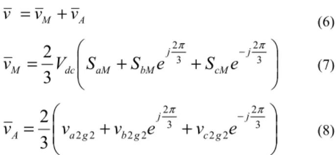
(4) ⎥ ⎥ ⎥ ⎦ ⎤ ⎢ ⎢ ⎢ ⎣ ⎡ − − − ⎥ ⎥ ⎥ ⎦ ⎤ ⎢ ⎢ ⎢ ⎣ ⎡ − − − − − − = ⎥ ⎥ ⎥ ⎦ ⎤ ⎢ ⎢ ⎢ ⎣ ⎡ 2 2 1 1 2 2 1 1 2 2 1 1 2 1 1 1 2 1 1 1 2 3 1 g c g c g b g b g a g a cs bs as v v v v v v v v v (5)Using space vector representation, the output voltage vector v of the combined inverter can be written as the sum of the main and auxiliary inverter voltage vectors, vM and vA, as in (6). Equations (7), (8) and (2) are used to derive main and auxiliary inverter voltage vectors from the switching states.
A M
v
v
v
=
+
(6)⎟⎟
⎠
⎞
⎜⎜
⎝
⎛
+
+
=
− 3 2 3 23
2
π j π cM j bM aM dc MV
S
S
e
S
e
v
(7)⎟⎟
⎠
⎞
⎜⎜
⎝
⎛
+
+
=
− 3 2 2 2 3 2 2 2 2 23
2
π j π g c j g b g a Av
v
e
v
e
v
(8)The combined motor control and energy management functions of the double ended inverter system can be achieved in three different methods [11]. The first one is called the unity power factor control method. In this method, auxiliary inverter voltage vector vA is aligned with the current vector i in order to optimize its energy flow. In the second method, auxiliary inverter voltage vector is made to be perpendicular to the current vector and therefore, it is called the voltage quadrature control method. In this operation, auxiliary inverter acts as a source of reactive power. Therefore, the whole demand is supplied by the main inverter. The third method is called the optimum inverter utilization control method. Phase voltages of the two inverters are set to be 1800 out of phase in this method and hence it produces the maximum output voltage of the double ended inverter. Therefore, the third method is selected for the proposed system. Inverter output voltages are said to be co-linear under this mode of operation and hence the voltage ratio k of the double ended inverter can be introduced as in (9) and (10). Since the output ac currents of the two inverters are the same, the voltage ratio k also defines the power sharing between inverters as explained in (11) and (12) [12]. Therefore, hereafter the voltage ratio k will be referred to as the power sharing coefficient as well.
v
k
v
M=
(9)(
k
)
v
v
A=
1
−
(10) L M Mv
i
kP
P
=
⋅
=
2
3
(11) L A Av
i
k
P
P
(
1
)
2
3
−
=
⋅
=
(12) A M LP
P
P
=
+
(13) sc b AP
P
P
=
+
(14)where PL accounts for the motor output power and possible losses in the motor, PM is the main inverter power and PA is the auxiliary inverter power.
Total power of the auxiliary inverter can be written as the sum of the battery power and supercapacitor power as in (14). Power losses in the auxiliary inverter are neglected in (14). Power sharing between the battery and the supercapacitor is a complex issue since the proposed system can operate in any of the seven operating modes in a drive cycle. An analysis on these operating modes and corresponding power sharing techniques are discussed in Section IV. More details on the modulation strategy used in this study and effects of dc-link voltage variations can be found in [13][14].
III. MACHINE EQUATIONS A. PMSM Model
The permanent magnet synchronous machine (PMSM) model in the synchronous reference frame is shown in Fig. 2. Based on this model, two expressions can be derived for d-q axis voltages as in (15) and (16) respectively.
dt
di
L
R
i
v
d d q e s d d=
−
ω
ϕ
+
(15)dt
di
L
R
i
v
q q d e s q q=
+
ω
ϕ
+
(16)where vd and vq are d-q axis voltages, id and iq are d-q axis currents, Rs is stator resistance, Ld and Lq are d-q axis inductances and ωe is electrical rotational speed. φd and φq are magnetic flux components in d-q axes and their magnitudes are determined using (17) and (18). φm in (17) is the flux produced by permanent magnets of the motor. Electric torque produced by the motor is given by (19).
m d d d
L
i
ϕ
ϕ
=
+
(17) q d q=
L
i
ϕ
(18)(
d q qd)
ep
i
i
T
=
φ
−
ϕ
2
3
(19)where p is the number of pole pairs.
Angular acceleration of the motor and the relationship between the electrical rotational speed and the mechanical rotational speed are given in (20) and (21) respectively.
(
e L)
mT
T
J
−
=
1
ω
(20) m ep
ω
ω
=
(21)where J is the inertia and ωm is the mechanical rotational speed of the motor.
Fig. 2. PMSM model in the synchronous reference frame.
Fig. 3. Vector diagram showing zero direct axis current control of the PMSM.
Fig. 4. Speed controller block diagram. B. Motor controller
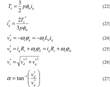
The zero d-axis current control technique is used to control the speed of the motor. In this method d-axis component of the stator current is maintained at zero. As a result d-axis component of the magnetic flux becomes equal to the flux produced by the permanent magnet of the motor as shown in Fig. 3. This flux, together with the q-axis current, produces the electrical torque according to (22), which is an analogue to the operation of dc motors. Therefore, in the speed controller shown in Fig. 4 the q-axis current is controlled to control the speed of the motor.
q m e
p
i
T
φ
2
3
=
(22) m e qp
T
i
φ
3
2
* *=
(23) q d e q e dL
i
v
*=
−
ω
ϕ
=
−
ω
(24) m e s q d e s q qi
R
i
R
v
*=
+
ω
ϕ
=
+
ω
ϕ
(25) 2 * 2 * * q d sv
v
v
=
+
(26)⎟
⎟
⎠
⎞
⎜
⎜
⎝
⎛
=
− * * 1tan
q dv
v
α
(27)In the speed controller shown in Fig. 4, the reference angular speed is compared with the actual speed of the motor and the error is passed through a PI controller. Output of the PI controller is the torque reference which is used in (23) to derive the required q-axis current. The d-axis current reference is set to zero. Based on these current references, required voltage components can be calculated using (24) and (25). Equations (26) and (27) are used to determine the amplitude and the angle of the inverter output voltage vector.
IV. OPERATING MODES
The proposed system has seven different operating modes which are defined on the basis of power flow. The selection of the suitable energy storage element depends on the mode of operation. These seven operating modes can be explained as follows.
A. Mode 1: motor normal start
In this mode, peak power required for acceleration is entirely supplied by the supercapacitor. Therefore following two conditions hold true.
0
,
0
>
=
P
Ak
(28) sc AP
P
=
(29)B. Mode 2: motor boost start
In this mode, part of the peak power required for acceleration is supplied by the primary source. The rest is supplied by the supercapacitor. This is very useful for implementing a smooth transition from supercapacitor to the primary source. Following conditions apply for this mode of operation.
0
,
1
0
<
k
<
P
A>
(30) sc AP
P
=
(31)C. Mode 3: motor super boost start
In this mode, battery is also used to supply the peak power required for acceleration. Therefore, all three sources are in operation under this mode. This is useful in rapid acceleration or uphill acceleration [15]. Following conditions are true for this mode of operation.
0
,
1
0
<
k
<
P
A>
(32) sc B AP
P
P
=
+
(33)D. Mode 4: motor normal run
When the motor is in the normal run primary source is supposed to supply the whole demand. Therefore, both battery and the supercapacitor are disengaged in this mode of operation. The corresponding conditions are as follows.
0
,
1
=
=
P
Ak
(34)E. Mode 5: motor normal run with battery and/or supercapacitor charging
In this mode of operation, part of the primary source power is used to charge the battery and/or the supercapacitor [16]. The corresponding conditions are as follows.
0
,
1
<
>
P
Ak
(35) sc B AP
P
P
=
+
(36)F. Mode 6: motor normal run with battery discharging In this particular mode of operation, the primary source is assisted with the battery especially for hill climbing. Therefore, the following conditions are true for this mode.
0
,
1
0
<
k
<
P
A>
(37) B AP
P
=
(38)G. Mode 7: motor breaking
During motor breaking, the supercapacitor is used to absorb the kinetic energy of the vehicle and hence the following two conditions hold true.
0
,
0
<
=
P
Ak
(39) sc AP
P
=
(40) V. SIMULATION RESULTSThe proposed direct integration scheme and its operating modes have been verified using three sets of computer simulations on the MATLAB/SIMULINK digital simulation platform. The speed profile used in these simulations is shown in Fig. 5(a) which is equivalent to a 60s drive cycle in real world. In the first simulation, peak power required for acceleration is supplied only by the supercapacitor bank and hence the system operates in mode 1.
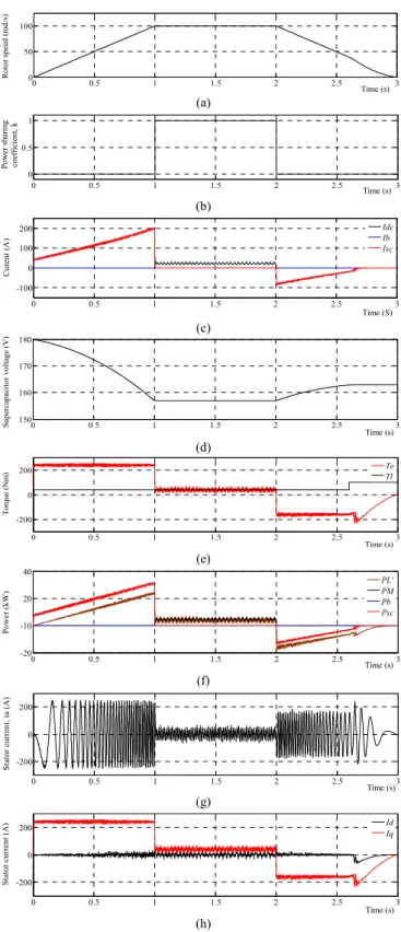
0 0.5 1 1.5 2 2.5 3 0 50 100 Time (s) R ot or s pee d (r ad /s ) (a) 0 0.5 1 1.5 2 2.5 3 0 0.5 1 Time (s) Po w er s ha ri ng co effi ci en t, k (b) 0 0.5 1 1.5 2 2.5 3 -100 0 100 200 Time (S) C ure nt (A ) Idc Ib Isc (c) 0 0.5 1 1.5 2 2.5 3 150 160 170 180 Time (s) Su pe rca pac it or v ol tag e (V) (d) 0 0.5 1 1.5 2 2.5 3 -200 0 200 Time (s) T or que ( N m ) TeTl (e) 0 0.5 1 1.5 2 2.5 3 -20 -10 20 40 Time (s) Po w er ( kW ) PL' PM Pb Psc (f) 0 0.5 1 1.5 2 2.5 3 -200 0 200 Time (s) S tat or cu rr en t, i a ( A ) (g) 0 0.5 1 1.5 2 2.5 3 -200 0 200 Time (s) St at or cu rr en t (A) Id Iq (h)
Fig. 5. A drive cycle with modes 1, 4 and 7 (a) speed profile, (b) power sharing coefficient, (c) battery, supercapacitor and primary source current, (d) supercapacitor voltage, (e) electric torque and load torque, (f) input and
output power (g) stator current of the a-phase, (h) stator current. During the constant speed period, primary source is used to supply the whole demand. Therefore, corresponding mode of operation is 4. During deceleration, supercapacitor bank is used to store breaking energy and hence the system operates in the 7th mode. The corresponding variation of the power sharing coefficient is shown in Fig. 5(b). It is 0 during acceleration and braking which indicates that the main inverter is in idle state. During the constant speed period
power sharing coefficient is 1 which means that the total power is supplied by the primary source. Variations of battery, supercapacitor and primary source currents are shown in Fig. 5(c). It clearly shows that the supercapacitor gets discharged during acceleration and gets charged during braking. The corresponding supercapacitor voltage variation is shown in Fig. 5(d). However, there is a net loss of energy stored in the supercapacitor at the end of each drive cycle. It should be replenished by the primary source during constant speed operation.
Variations of the electric torque and load torque are shown in Fig. 5(e). A sudden increase of load torque can be seen near the end of the braking period. This indicates the use of mechanical braking at low speeds. Charging of the supercapacitor is ceased at this point and hence the application of mechanical braking is necessary to maintain the speed profile. The corresponding supercapacitor power, primary source power and load power variations are shown in Fig. 5(f). Stator current variation of the a-phase is shown in Fig. 5(g). The increase of stator current near the end of braking is due to the cease of supercapacitor charging, which is equivalent to short circuiting of motor terminals in the generating mode. Stator currents in the synchronous reference frame are shown in Fig. 5(h). The d-axis component of the stator current is maintained at zero.
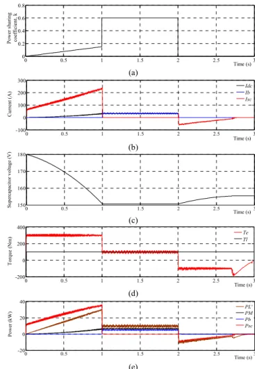
0 0.5 1 1.5 2 2.5 3 0 0.5 1 1.5 Time (s) Po w er sh ar in g co ef fi cien t, k (a) 0 0.5 1 1.5 2 2.5 3 -100 0 100 200 Time (s) C urren t (A) Idc Ib Isc (b) 0 0.5 1 1.5 2 2.5 3 150 160 170 180 Time (s) Su pe rc ap ac it or vol ta ge ( V ) (c) 0 0.5 1 1.5 2 2.5 3 -200 0 200 Time (s) T or que ( N m ) TeTl (d) 0 0.5 1 1.5 2 2.5 3 -20 0 20 40 Time (s) P ow er (k W ) PL'PM Pb Psc (e)
Fig. 6. A drive cycle with modes 2, 5 and 7 (a) power sharing coefficient, (b) battery, supercapacitor and primary source current, (c) supercapacitor
voltage, (d) electric torque and load torque, (e) input and output power.
The same speed profile, shown in Fig. 5(a), is used in the second set of simulations as well. But the operating modes for acceleration and constant speed region are changed to 2 and 5 respectively. In mode 2, peak power required for acceleration is shared between the supercapacitor and the primary source. However, the share of primary source power is very small as indicated by the corresponding power sharing coefficient and current waveforms in Fig. 6(a) and Fig. 6(b) respectively. But this mode is very useful for smooth transition from supercapacitor to the primary source. During the constant speed period, the 5th operating mode is used. In this mode of operation, the primary source produces more power than the required amount, as indicated by the increase of power sharing coefficient from 1 to 1.5 in Fig. 6(a). This surplus of power is stored in the battery with a charging current as shown in Fig. 6(b). The drop of the supercapacitor voltage is reduced as shown in Fig. 6(c) due to the support from the primary source. The corresponding torque and power variations are shown in Fig. 6(d) and Fig. 6(e) respectively.
The third simulation was carried out to show the performance of mode 6 which is used to support the primary source during the constant speed operation. This mode is essential when the primary source is unable to supply the demand, especial in hill climbing. The same speed profile, shown in Fig. 5(a), is used in this simulation as well.
0 0.5 1 1.5 2 2.5 3 0 0.2 0.4 0.6 0.8 Time (s) P ow er s ha ri ng co ef fi cien t, k (a) 0 0.5 1 1.5 2 2.5 3 -100 0 100 200 300 Time (s) C urr en t (A ) IdcIb Isc (b) 0 0.5 1 1.5 2 2.5 3 150 160 170 180 Time (s) S upe rc ap ac it or vol ta ge ( V ) (c) 0 0.5 1 1.5 2 2.5 3 -200 0 200 400 Time (s) T or que ( N m ) TeTl (d) 0 0.5 1 1.5 2 2.5 3 -20 0 20 40 Time (s) Po w er ( kW ) PL'PM Pb Psc (e)
Fig. 7. A drive cycle with modes 2, 6 and 7 (a) power sharing coefficient, (b) battery, supercapacitor and primary source current, (c) supercapacitor
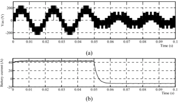
0 0.01 0.02 0.03 0.04 0.05 0.06 0.07 0.08 0.09 0.1 -200 0 200 Time (s) Va s ( V ) (a) 0 0.01 0.02 0.03 0.04 0.05 0.06 0.07 0.08 0.09 0.1 -20 0 20 40 Time (s) B at te ry c urre nt (A ) (b)
Fig. 8. (a) Inverter output voltage, (b) battery current.
As in the previous simulation, the 2nd operating mode is used for acceleration and the 7th mode for braking. The corresponding variations of the power sharing coefficient and currents are shown in Fig. 7(a) and Fig. 7(b) respectively. Power sharing coefficient is reduced during constant speed operation to allow room for battery discharge. Compared to previous simulations, supercapacitor voltage is reduced to a much lower value as shown in Fig. 7(c). This is due to the increase in load torque. The corresponding torque and power variations are shown in Fig. 7(d) and Fig. 7(e) respectively. Inverter output voltage and battery current are shown in Fig. 8(a) and Fig. 8(b) respectively to show the ability of the proposed modulation method to produce proper multilevel voltage waveforms in discharging and charging conditions. System parameters of the simulation setup are given in Table I.
TABLE I
SYSTEM PARAMETERS OF THE SIMULATION SETUP Main inverter dc-link voltage Vdc = 200V
Nominal battery voltage Vb = 150V
Maximum voltage of the supercapacitor bank Vsc,max = 180V
Capacitance of the supercapacitor bank Csc = 5F
Rated power of the PMSM 20kW Stator resistance Rs = 85mΩ
Stator inductance Ld, Lq = 0.2mH
Number of pole pairs P = 4 Torque constant of the PMSM 1
VI. CONCLUSION
This paper has proposed a novel direct integration scheme for battery and supercapacitor energy storage systems in hybrid electric vehicles. The inverter system used in this study consists of a two-level inverter and a three-level inverter which are coupled through open ends of the traction motor. A battery bank and a supercapacitor bank are directly connected across dc-link capacitors of the three-level inverter. This particular arrangement eliminates the need for additional dc-dc converters and thus reduces the cost, power loss and complexity. Seven different operating modes are suggested
for a typical drive cycle of a hybrid electric vehicle to improve the effective use of available energy. Simulation results verify the efficacy of the proposed scheme, and control techniques.
REFERENCES
[1] J. Voelcker, “One Million Plug-in Cars by 2015? [Update],” IEEE Spectrum, vol.48, no.4, pp.11-13, April 2011.
[2] A. Khaligh, and Li Zhihao, “Battery, Ultracapacitor, Fuel Cell, and Hybrid Energy Storage Systems for Electric, Hybrid Electric, Fuel Cell, and Plug-In Hybrid Electric Vehicles: State of the Art,” IEEE Trans. Veh. Technol., vol.59, no.6, pp.2806-2814, July 2010.
[3] J. Cao, and A. Emadi, “A New Battery/Ultra-Capacitor Hybrid Energy Storage System for Electric, Hybrid and Plug-in Hybrid Electric Vehicles,” IEEE Trans. Power Electron., early access May 2011. [4] P. Thounthong, V. Chunkag, P. Sethakul, B. Davat, and M. Hinaje,
“Comparative Study of Fuel-Cell Vehicle Hybridization with Battery or Supercapacitor Storage Device,” IEEE Trans. Veh. Technol., vol.58, no.8, pp.3892-3904, Oct. 2009.
[5] P. Thounthong, and S. Rael, “The benefits of hybridization,” IEEE Industrial Electronics Magazine, vol.3, no.3, pp. 25-37, Sept. 2009. [6] A. M. van Voorden, L. M. R. Elizondo, G. C. Paap, J. Verboomen, and
L. van der Sluis, “The Application of Super Capacitors to relieve Battery-storage systems in Autonomous Renewable Energy Systems,” in Proc. IEEE Power Tech., pp. 479-484, July 2007.
[7] M. Zandi, A. Payman, J. P. Martin, S. Pierfederici, B. Davat, and F. Meibody-Tabar, “Energy Management of a Fuel Cell/ Supercapacitor/ Battery Power Source for Electric Vehicular Applications,” IEEE Trans. Veh. Technol., vol.60, no.2, pp.433-443, Feb. 2011.
[8] Shuai Lu, K. A. Corzine, and M. Ferdowsi, “A Unique Ultracapacitor Direct Integration Scheme in Multilevel Motor Drives for Large Vehicle Propulsion,” IEEE Trans. Veh. Technol., vol. 56, no. 4, pp. 1506-1515, July 2007.
[9] Shuai Lu, K. A. Corzine, and M. Ferdowsi, “A New Battery/Ultracapacitor Energy Storage System Design and Its Motor Drive Integration for Hybrid Electric Vehicles,” IEEE Trans. Veh. Technol.,vol.56, no.4, pp.1516-1523, July 2007.
[10] S. M. Lukic, S. G. Wirasingha, F. Rodriguez, Jian Cao, and A. Emadi, “Power Management of an Ultracapacitor/Battery Hybrid Energy Storage System in an HEV,” in Proc. IEEE Vehicle Power and Propulsion Conf., VPPC 2006, 6-8 Sept. 2006.
[11] B. A. Welchko, “A double-ended inverter system for the combined propulsion and energy management functions in hybrid vehicles with energy storage,” in Proc. IEEE Ind. Electron. Soc. Conf., IECON 2005, Nov. 2005.
[12] G. Grandi, C. Rossi, D. Ostojic, and D. Casadei, “A New Multilevel Conversion Structure for Grid-Connected PV Applications,” IEEE Trans. Ind. Electron., vol.56, no.11, pp.4416-4426, Nov. 2009. [13] S. D. G. Jayasinghe, D. M. Vilathgamuwa, and U. K. Madawala,
“Connecting two wind turbine generators to the grid using only one three level NPC inverter,” in Proc. IEEE Ind. Electron. Soc. Conf., IECON 2010, Nov. 2010.
[14] S. D. G. Jayasinghe, D. M. Vilathgamuwa, and U. K. Madawala, “A direct integration scheme for battery-supercapacitor hybrid energy storage systems with the use of grid side inverter,” in Proc. IEEE Applied Power Electronics Conference and Exposition, APEC 2011, pp.1388-1393, 6-11 March 2011.
[15] Hyunjae Yoo, Seung-Ki Sul, Yongho Park, and Jongchan Jeong, “System Integration and Power-Flow Management for a Series Hybrid Electric Vehicle Using Supercapacitors and Batteries,” IEEE Trans. Ind. Appl., vol.44, no.1, pp.108-114, Jan.-Feb. 2008.
[16] C. Attaianese, E. D. Grotta, M. Di Monaco, and G. Tomasso, “Fuel cell based traction drive with supercapacitor power boost control,” in Proc. IEEE Electrical Systems for Aircraft, Railway and Ship Propulsion Conf., ESARS 2010 , 19-21 Oct. 2010.