Millimetre-Wave Fibre-Wireless
Technologies for 5G Mobile Fronthaul
Abayomi Temitope Latunde
A thesis submitted to the University of Hertfordshire in partial
fulfilment of the requirements for the degree of Doctor of
Philosophy
The programme of research was carried out in the Science and
Technology Research Institute (STRI),
Engineering and Technology,
University of Hertfordshire,
United Kingdom.
i
Abstract
The unprecedented growth in mobile data traffic, driven primarily by bandwidth rich applications and high definition video is accelerating the development of fifth generation (5G) mobile network. As mobile access network evolves towards centralisation, mobile fronthaul (MFH) architecture becomes essential in providing high-capacity, ubiquitous and yet affordable services to subscribers. In order to meet the demand for high data rates in the access, Millimetre-wave (mmWave) has been highlighted as an essential technology in the development of 5G-new radio (5G-NR). In the present MFH architecture which is typically based on common public radio interface (CPRI) protocol, baseband signals are digitised before fibre transmission, featuring high overhead data and stringent synchronisation requirements. A direct application of mmWave 5G-NR to CPRI digital MFH, where signal bandwidth is expected to be up to 1GHz will be challenging, due to the increased complexity of the digitising interface and huge overhead data that will be required for such bandwidth. Alternatively, radio over fibre (RoF) technique can be employed in the transportation of mmWave wireless signals via the MFH link, thereby avoiding the expensive digitisation interface and excessive overhead associated with its implementation. Additionally, mmWave carrier can be realised with the aid of photonic components employed in the RoF link, further reducing the system complexity. However, noise and nonlinearities inherent to analog transmission presents implementation challenges, limiting the system dynamic range. Therefore, it is important to investigate the effects of these impairments in RoF based MFH architecture.
This thesis presents extensive research on the impact of noise and nonlinearities on 5G candidate waveforms, in mmWave 5G fibre-wireless MFH. Besides orthogonal frequency division multiplexing (OFDM), another radio access technology (RAT) that has received significant attention is filter bank multicarrier (FBMC), particularly due to its high spectral containment and excellent performance in asynchronous transmission. Hence, FBMC waveform is adopted in this work to study the impact of noise and nonlinearities on the mmWave fibre-wireless MFH architecture. Since OFDM is widely deployed and it has been adopted for 5G-NR, the performance of OFDM and FBMC based 5G mmWave RAT in fibre-wireless MFH architecture is compared for several implementations and transmission scenarios.
To this extent, an end-to-end transmission testbed is designed and implemented using industry standard VPI Transmission Maker® to investigate five mmWave upconversion techniques. Simulation results show that the impact of noise is higher in FBMC when the
ii
signal-to-noise (SNR) is low, however, FBMC exhibits better performance compared to OFDM as the SNR improved. More importantly, an evaluation of the contribution of each noise component to the overall system SNR is carried out. It is observed in the investigation that noise contribution from the optical carriers employed in the heterodyne upconversion of intermediate frequency (IF) signals to mmWave frequency dominate the system noise. An adaptive modulation technique is employed to optimise the system throughput based on the received SNR. The throughput of FBMC based system reduced significantly compared to OFDM, due to laser phase noise and chromatic dispersion (CD). Additionally, it is shown that by employing frequency domain averaging technique to enhance the channel estimation (CE), the throughput of FBMC is significantly increased and consequently, a comparable performance is obtained for both waveforms.
Furthermore, several coexistence scenarios for multi-service transmission are studied, considering OFDM and FBMC based RATs to evaluate the impact inter-band interference (IBI), due to power amplifier (PA) nonlinearity on the system performance. The low out of band (OOB) emission in FBMC plays an important role in minimising IBI to adjacent services. Therefore, FBMC requires less guardband in coexistence with multiple services in 5G fibre-wireless MFH. Conversely, OFDM introduced significant OOB to adjacent services requiring large guardband in multi-service coexistence transmission scenario.
Finally, a novel transmission scheme is proposed and investigated to simultaneously generate multiple mmWave signals using laser heterodyning mmWave upconversion technique. With appropriate IF and optical frequency plan, several mmWave signals can be realised. Simulation results demonstrate successful simultaneous realisation of 28GHz, 38GHz, and 60GHz mmWave signals.
iii
Acknowledgement
First of all, I will like to thank my supervisor Dr Pandelis Kourtessis, for allowing me to carry this research and his continuous support throughout the course of my study. I’m also privileged to have had Dr Milos Milosavljevic in my supervisory team, who constantly inspired and encouraged me to do more than just enough. I also want to thank Prof. John M. Senior for his advice every time we had team meetings.
Many thanks to my colleagues at D437 and D400 for their support, especially Matt Robinson for valuable discussions and ideas, and also for his help in times I had problems with my PC. I also want to specially thank my wife and daughter for their support, emotionally, psychologically and in prayers. You have been so wonderful, believing in me and always encouraging me. Whenever I get distracted or tired, Tolorunni says “Daddy do your work”.
I will like to appreciate my sister for financial support since it all started; you sacrificed a lot for me to get here. My gratitude also goes to Mr Otunla for his financial support and helping with my scholarship.
I want to use this opportunity to thank the Niger Delta Scholarship scheme for sponsoring my research; I couldn’t have done it without their financial support.
Above all, I give all glory to God Almighty for giving me the grace and strength to carry out this research, “for by strength shall no man prevail” (1 Sam: 2:9b)
iv
Table of Content
Abstract... i
Acknowledgement ... iii
Table of Content ... iv
List of Figures ... viii
List of Tables ... xiii
Abbreviations ... xiv
List of publications ... xix
1. Towards High Capacity 5G Mobile Broadband Access Network ... 1
1.1. Introduction ... 1
1.2. State-of-the-Art 4G Mobile Broadband and Beyond ... 2
1.3. The IMT 2020 Requirements for 5G ... 2
1.3.1. Research Initiatives towards 5G... 3
1.4. Research Motivation and Objectives ... 5
1.5. Research Contributions ... 6
1.6. Thesis Outline ... 7
2. Enabling Technologies for High-Capacity 5G Mobile Broadband Access ... 8
2.1. Introduction ... 8
2.2. Cloud Radio Access Network Architecture ... 8
2.3. Transport Technologies for Mobile Fronthaul ... 10
2.3.1. Radio over Fibre Technology ... 10
2.3.1.1. Digital Radio over Fibre ... 11
2.3.1.2. Analog Radio over Fibre ... 12
2.4. Millimetre-wave Technology ... 14
2.5. Photonics Techniques for Millimetre-wave Generation ... 17
2.5.1. Photonic-aided Millimetre-wave Generation using MZMs ... 17
2.5.2. Photonic-aided Millimetre-wave Generation using Lasers ... 21
v
2.6. Summary ... 26
3. Design of Millimetre-Wave Fibre-Wireless Testbed for 5G Mobile Fronthaul ... 27
3.1. Introduction ... 27
3.2. The VPI Photonic Design Suite ... 27
3.2.1. Simulation of ARoF in VPI... 29
3.2.2. MATLAB-VPI co-simulation Technique ... 31
3.3. Self-Heterodyne Technique for Millimetre-wave Signal Downconversion ... 31
3.3.1. System Model and Performance Analysis ... 33
3.4. Filter Bank Multicarrier Systems Architecture ... 36
3.4.1. Channel Estimation in FBMC ... 42
3.4.1.1. Channel Estimation using Pairs of Pilots ... 43
3.4.1.2. Channel Estimation using Interference Approximation ... 43
3.4.1.3. Performance Evaluation of Preamble-based Channel Estimation for FBMC 44 3.4.2. Peak to Average Power Ratio in FBMC ... 45
3.5. Summary ... 46
4. Millimetre-wave Optical Transceivers for Next Generation Fibre-Wireless Architectures 48 4.1. Introduction ... 48
4.2. Millimetre-Wave Upconversion Techniques for Fibre-Wireless 5G Mobile Fronthaul ... 48
4.2.1. Millimetre-wave Upconversion using Electrical Local Oscillator... 49
4.2.2. Millimetre-wave Upconversion using MZM ... 58
4.2.3. Millimetre-wave Upconversion using Laser heterodyning Technique ... 65
4.3. Comparison of Millimetre-wave Techniques ... 70
4.4. Summary ... 72
5. Impact of Noise on Millimetre-Wave Signal Generated using Laser Heterodyning ... 73
5.1. Introduction ... 73 5.2. SNR of Millimetrewave IF over Fibre Signal Generated using Laser Heterodyning
vi
5.2.1. Noise Generated in the Transmitter ... 74
5.2.1.1. Relative Intensity Noise ... 74
5.2.1.2. Laser Phase Noise ... 75
5.2.1.3. Amplified Spontaneous Emission ... 78
5.2.2. Noise Generated in the Receiver ... 79
5.2.2.1. Thermal Noise ... 79
5.2.2.2. Shot Noise ... 79
5.2.3. SNR of the Millimetrewave Signal after O/E Conversion ... 80
5.3. Noise Effects on Millimetre-wave IF over Fibre Signal based on uncorrelated Lasers ... 81
5.3.1. Impact of RIN on the system performance ... 83
5.3.2. Impact of ASE Noise ... 84
5.3.3. Impact of CD-induced CPN ... 85
5.3.4. Impact of Laser Linewidth ... 86
5.3.5. Impact of Fibre Length ... 87
5.3.6. Impact of Noise on IF Signal Bandwidth ... 89
5.4. System Performance Optimisation based on the Received SNR and Frequency Domain Averaging ... 94
5.5. Summary ... 100
6. Nonlinear Impairments in Millimeter-Wave 5G Multi-Service over Fibre Systems ... 102
6.1. Introduction ... 102
6.2. Nonlinear Subcarrier Intermodulation in Multi-Service Systems ... 103
6.2.1. Power Amplifier Modelling... 103
6.3. Impact of PA Nonlinearity in Millimetre-wave IF over Fibre Upconversion using Laser Heterodyning ... 105
6.3.1. Scenario 1 ... 107
6.3.2. Scenario 2 ... 109
6.3.3. Scenario 3 ... 110
6.3.4. Scenario 4 ... 111
vii
6.5. Impact of PA Nonlinearity in Uplink Multi-User Access Systems ... 118
6.6. Summary ... 119
7. Coexistence of Multiple 5G Services in a Photonic Millimetre-wave Mobile Fronthaul121 7.1. Introduction ... 121
7.2. Simultaneous Generation of Multiple Millimetre-wave Signals based on Optical Heterodyning ... 121
7.3. Simulation Setup ... 124
7.3.1. Performance Evaluation for 28GHz and 38GHz ... 127
7.3.2. Performance Evaluation for 28GHz and 60GHz ... 130
7.3.3. Performance Evaluation for 28GHz, 38GHz and 60GHz ... 133
7.4. Summary ... 135
8. Conclusion and Future Works ... 137
8.1. Thesis Summary ... 137
8.2. Future Works ... 140
viii
List of Figures
Figure 1.1: Cisco VNI Report for Global Mobile Data Traffic [1] ... 1
Figure 1.2: High-Level Requirements for 5G ... 3
Figure 2.1: C-RAN Architecture ... 9
Figure 2.2: Radio-over-Fibre ... 11
Figure 2.3: Digital-over-Fibre (a) BB (b) IF (c) RF ... 12
Figure 2.4: Analog-over-Fibre (a) IF-over-Fibre (b) RF-over-Fibre... 13
Figure 2.5: Atmospheric absorption at different frequency bands [39] ... 15
Figure 2.6: Samsung end-to-end 5G FWA network [78] ... 16
Figure 2.7: Schematic of DE-MZM (a) DE-MZM transfer function (b) ... 18
Figure 2.8: Optical signal after E/O at (a) Maximum point (b) Quadrature point (c) Null point ... 18
Figure 2.9: Cascaded MZM and phase modulator for frequency tripling [99] ... 19
Figure 2.10: Cascaded DE-MZMs for frequency quadrupling [100] ... 20
Figure 2.11: Schematic of two stage upconversion to generate 8x the LO frequency [102] . 20 Figure 2.12: The principle and schematic of the mmWave inter- and intra-RAT carrier aggregation in Het-Net based on optical band mapping [103] ... 21
Figure 2.13: Schematic of optical mmWave generation using gain-switched DFB laser [106] ... 22
Figure 2.14: Schematic of 60GHz RoF system based on PMLLD [107] ... 23
Figure 2.15: Different Schemes to generate mmWave carrier using unlocked LDs [110] .... 24
Figure 2.16: Principle of generation and transmission of 60GHz UWB Signal [111] ... 24
Figure 3.1: (a) Laser Bias current vs Output Power (b) and Bias current vs Linewidth ... 28
Figure 3.2: Bias current vs Laser RIN ... 28
Figure 3.3: OFDM Transceiver Design in VPI (a) Transmitter (b) Receiver ... 29
Figure 3.4: ARoF Simulation Schematic ... 29
Figure 3.5: Received constellation at (a) 0km (b) 25km (c) 50km (d) 100km ... 30
Figure 3.6: MATLAB VPI co-simulation Structure ... 31
Figure 3.7: Proposed network architecture ... 32
Figure 3.8: Simulation setup of the proposed architecture ... 33
Figure 3.9: Effect of Laser linewidths for BTB ... 35
Figure 3.10: BER vs Received Power at PD for BTB, 20km and 40km Fibre ... 36
Figure 3.11: (a) FBMC baseband transceiver (b) OFDM baseband transceiver ... 38
Figure 3.12: Frequency Time phase space lattice of the FBMC system ... 38
ix
Figure 3.14: Magnitude response of the prototype filter for K =1:4 ... 40
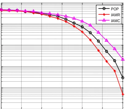
Figure 3.15: Preamble Structures for FBMC (a) POP (b) IAMR (c) IAMC ... 43
Figure 3.16: BER of FBMC for different preamble-based CE methods ... 45
Figure 3.17: Simulated PAPR for FBMC, FBMC with 25% clipping and OFDM ... 46
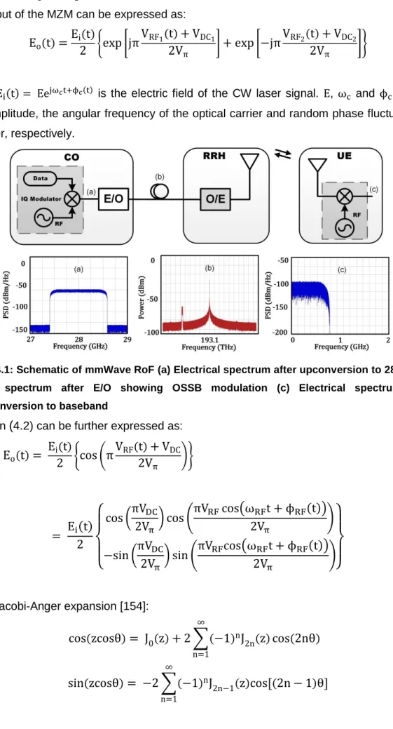
Figure 4.1: Schematic of mmWave RoF (a) Electrical spectrum after upconversion to 28GHz (b) Optical spectrum after E/O showing OSSB modulation (c) Electrical spectrum after downconversion to baseband ... 50
Figure 4.2: EVM vs RF drive power for mmWave RFoF using electrical LO (a) OFDM (b) FBMC ... 53
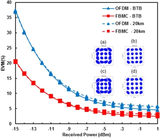
Figure 4.3: EVM vs Received Power for mmWave RFoF using electrical LO (a) OFDM BTB (b) FBMC BTB (c) OFDM 20km (d) FBMC 20km ... 54
Figure 4.4: mmWave IF-over-Fibre using electrical LO. (a) Optical spectrum after E/O showing OSSB modulation (b) Electrical spectrum after upconversion to 28GHz (c) Electrical spectrum after downconversion to baseband ... 56
Figure 4.5: EVM vs IF drive power for mmWave IFoF using electrical LO (a) OFDM (b) FBMC ... 57
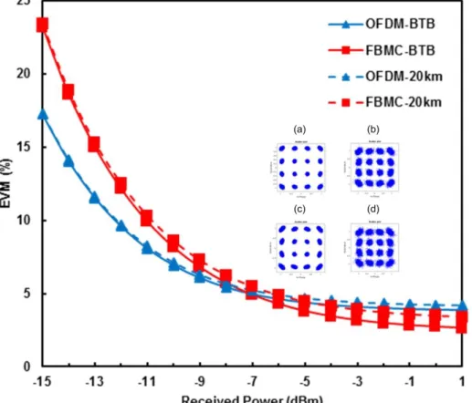
Figure 4.6: EVM vs Received optical power for mmWave IFoF using electrical LO (a) OFDM BTB (b) FBMC BTB (c) OFDM 20km (d) FBMC 20km ... 58
Figure 4.7: mmWave IFoF using cascaded MZMs (a) Optical spectrum after second MZM (b) The spectrum of IF OFDM after downconversion (c) The spectrum of IF FBMC after downconversion ... 59
Figure 4.8: EVM vs IF drive power for mmWave IFoF using cascaded MZMs (a) OFDM (b) FBMC ... 61
Figure 4.9: EVM vs Received optical power for mmWave IFoF using cascaded MZMs (a) OFDM BTB (b) FBMC BTB (c) OFDM 20km (d) FBMC 20km ... 62
Figure 4.10: mmWave IFoF using DML and MZM (a) Optical spectrum after the MZM (b) The spectrum of IF OFDM after downconversion (c) The spectrum of IF FBMC after downconversion ... 63
Figure 4.11: EVM vs IF drive power for mmWave IFoF using DML and MZM (a) OFDM (b) FBMC ... 64
Figure 4.12: EVM vs Received optical power for mmWave IFoF using DML and MZM (a) OFDM BTB (b) FBMC BTB (c) OFDM 20km (d) FBMC 20km ... 64
Figure 4.13: mmWave IFoF using Laser Heterodyning (a) Optical spectrum after the optical coupler (b) The spectrum of IF OFDM after downconversion (c) The spectrum of IF FBMC after downconversion ... 66
Figure 4.14: EVM vs IF drive power for mmWave IFoF using laser heterodyning (a) OFDM (b) FBMC ... 68
x
Figure 4.15: EVM vs Received optical power for mmWave IFoF using laser heterodyning (a)
OFDM BTB (b) FBMC BTB (c) OFDM 20km (d) FBMC 20km ... 69
Figure 5.1: Noise Source in mmWave System using laser heterodyning ... 74
Figure 5.2: Simulation Setup. ... 81
Figure 5.3: DSP Transceiver design for the IF Signals: (a) FBMC (b) OFDM ... 82
Figure 5.4: Received SNR vs RIN for OFDM and FBMC ... 84
Figure 5.5: SNR degradation due to ASE ... 85
Figure 5.6: SNR degradation due to CPN ... 86
Figure 5.7: SNR degradation due to laser linewidth ... 87
Figure 5.8: SNR degradation due to fibre length ... 88
Figure 5.9: EVM vs Subcarrier Number after 40km fibre ... 89
Figure 5.10: EVM vs Subcarrier Number after 100km fibre ... 90
Figure 5.11: EVM vs IF bandwidth after 40km fibre ... 91
Figure 5.12: Received constellation after 40km fibre and 2MHz linewidth for 2nd, 64th and 128th subcarriers after equalisation in 2GHz (a) OFDM (b) FBMC ... 92
Figure 5.13 EVM vs IF Bandwidth for 100km fibre ... 93
Figure 5.14: Subcarrier SNR for 10.1MHz Laser Configuration and 2GHz IF bandwidth (a) 40km (b) 100km ... 93
Figure 5.15: Schematic of transmission channel with CSI feedback for adaptive modulation ... 94
Figure 5.16: ISFA averaging window for 2GHz OFDM and FBMC after 40km ... 95
Figure 5.17: Bit-loading profiles for 2MHz laser and 2GHz bandwidth after 40km (a) OFDM (b) FBMC ... 96
Figure 5.18: Received constellation after adaptive modulation with ISFA for 2MHz linewidth after 40km fibre (a)-(c) OFDM: 2-bits, 4-bits and 6-bits (d)-(f) FBMC: 2-bits, 4-bits and 6-bits ... 97
Figure 5.19: Bit-loading profiles for 10.1MHz linewidth and 2GHz bandwidth after 40km (a) OFDM (b) FBMC ... 97
Figure 5.20: Received constellation after adaptive modulation with ISFA for 10MHz linewidth after 40km fibre (a)-(c) OFDM: 2-bits, 4-bits and 6-bits (d)-(f) FBMC: 2-bits, 4-bits and 6-bits ... 98
Figure 5.21: ISFA averaging window for 1GHz OFDM and FBMC after 100km ... 98
Figure 5.22: Bit-loading profiles for 10.1MHz laser and 1GHz bandwidth after 100km (a) OFDM (b) FBMC ... 99
Figure 5.23: Received constellation after adaptive modulation with ISFA for 10MHz laser and 100km fibre (a)-(b) OFDM: 2-bits and 4-bits (c)-(d) FBMC: 2-bits and 4-bits ... 100
xi
Figure 6.2: AM/AM conversion of the PA ... 104
Figure 6.3: Frequency-domain response of nonlinear PA with two-tone excitation ... 105
Figure 6.4: Simulation setup for the multi-service over fibre with remote mmWave upconversion ... 106
Figure 6.5: (a) EVM as a function PA input power for OFDM and FBMC (b) PSDs of FBMC and OFDM at input and output of the PA at points (i) to (iv) (i.e. -50dBm, -30dBm, -15dBm and -5dBm) and corresponding constellations ... 108
Figure 6.6: EVM as a function of input power of service 1 ... 109
Figure 6.7: EVM as a function of input power of service 1 ... 110
Figure 6.8: Coexistence of FBMC and OFDM in multi-service transmission scenario... 111
Figure 6.9: EVM as a function nulled subcarriers on either side of the LTE-like signal (a) FBMC (b) OFDM ... 113
Figure 6.10: PSD of the integrated service (a) FBMC with the LTE zoomed out shown in the inset (b) OFDM with the LTE zoomed out shown in the inset ... 113
Figure 6.11: PSD of the Integrated Service before and after the notch filter (a) FBMC (b) OFDM ... 114
Figure 6.12: EVM as a function power difference between service 1 (FBMC and OFDM) and LTE signal as input power of LTE signal increased from -60dBm to -40dBm and the input of Service is fixed at -50dBm... 114
Figure 6.13: EVM as a function power difference between service 1 (FBMC and OFDM) and LTE signal as input power of service 1 increased from -50dBm to -30dBm and the input of LTE is fixed at -50dBm ... 115
Figure 6.14: EVM as a function of received power for FBMC and OFDM with and without in-band LTE ... 116
Figure 6.15: Constellation at +1dBm received power (a) FBMC /w LTE (b) OFDM /w LTE (c) FBMC w/o LTE (d) OFDM w/o LTE ... 117
Figure 6.16: EVM of LTE integrated with FBMC and OFDM as a function of received power ... 117
Figure 6.17: EVM as a function of PA Input power for DFT-s-FBMC and DFT-s-OFDM uplink signals ... 118
Figure 7.1: The proposed concept of multi-service and multi-operator coexistence in a shared MFH infrastructure ... 122
Figure 7.2: Frequency Plan and Multiplexing of multiple services coexistence in a shared MFH infrastructure (a) WDM Multiplexer and Demultiplexer (b) 25GHz DWDM grid (c) 50GHz DWDM grid (d) Nx1 Port WSS ... 123
Figure 7.3: Schematic for the simultaneous generation of multiple mmWave signals using one optical LO ... 125
xii
Figure 7.4: Spectrums (a) Optical spectrum before the PD (b) Electrical spectrum after the PD showing 28GHz and 38GHz (c) 28GHz Electrical spectrum (d) 38GHz Electrical spectrum ... 128 Figure 7.5: EVM as a function of received power using 200kHz combined laser linewidth (a) 28GHz OFDM and FBMC (b) 38GHz OFDM and FBMC (c) Constellation for 28GHz OFDM and FBMC at 7dBm received power (d) Constellation for 38GHz OFDM and FBMC at -7dBm received power ... 129 Figure 7.6: EVM as a function of received power using 2MHz combined laser linewidth (a) 28GHz OFDM and FBMC (b) 38GHz OFDM and FBMC (c) Constellation for 28GHz OFDM and FBMC at 7dBm received power (d) Constellation for 38GHz OFDM and FBMC at -7dBm received power ... 130 Figure 7.7: Spectrums at (a) Optical spectrum before the PD (b) Electrical spectrum after the PD showing 28GHz and 60GHz (c) 28GHz Electrical spectrum (d) 60GHz Electrical spectrum ... 131 Figure 7.8: EVM as a function of received power using 200kHz combined laser linewidth (a) 28GHz OFDM and FBMC (b) 60GHz OFDM and FBMC (c) Constellation for 28GHz OFDM and FBMC at 7dBm received power (d) Constellation for 60GHz OFDM and FBMC at -7dBm received power ... 132 Figure 7.9: EVM as a function of received power 2MHz combined laser linewidth (a) 28GHz OFDM and FBMC (b) 60GHz OFDM and FBMC (c) Constellation for 28GHz OFDM and FBMC at -7dBm received power (d) Constellation for 60GHz OFDM and FBMC at -7dBm received power... 133 Figure 7.10: (a) EVM as a function of received power for 28GHz OFDM, 38GHz OFDM and 60GHz FBMC (b) constellations at -7dBm received power with and without ISFA using UL laser as LO ... 134 Figure 7.11: (a) EVM as a function of received power for 28GHz OFDM, 38GHz OFDM and 60GHz FBMC (b) constellations at -7dBm received power with and without ISFA using remotely delivered LO ... 135
xiii
List of Tables
Table 2-1: The frequency above 6GHz for future development of IMT 2020 ... 16
Table 3-1: Simulation Parameters ... 30
Table 3-2: List of frequency coefficients for half Nyquist filter ... 37
Table 4-1: System parameters used in the simulation ... 52
Table 4-2: Performance Comparison of the investigated mmWave upconversion Techniques ... 71
Table 5-1: Source and type of noise generated by components ... 74
Table 5-2: Laser Configuration and Linewidth ... 86
Table 6-1: Scenarios used to investigate PA-induced IBI in multi-service mmWave MFH . 106 Table 6-2: System parameters used in the simulation ... 107
xiv
Abbreviations
3GPP Third Generation Partnership Project 4G Fourth Generation
5G Fifth Generation
5GPP Fifth Generation Partnership Project 5G-NR 5G-New Radio
ADC Analog-to-Digital Converter AFB Analysis Filter Bank
AM/AM Amplitude Modulation/Amplitude Modulation AON Active Optical Network
AWGN Additive White Gaussian Noise
AR Augmented Reality
ARoF Analog Radio over Fibre
ASE Amplified Spontaneous Emission
BB Baseband
BBU Baseband Unit
BER Bit Error Rate BPF Bandpass Filter
BS Base Station
BTB Back-to-Back
BPSK Binary Phase Shift Keying
BW Bandwidth
BWA Broadband Wireless Access CA Carrier Aggregation
CAGR Compound Annual Growth Rate CAPEX Capital Expenditure
CC Component Carrier
CD Chromatic Dispersion
CCDF Cumulative Complementary Distribution Function
CE Channel Estimation
CFO Carrier Frequency Offset CFR Channel Frequency Response
CMOS Complementary Metal Oxide Semiconductor CO Central Office
CoMP Cooperative Multipoint
xv CPE Customer Premises Equipment CPN Converted Phase Noise
CPRI Common Public Radio Interface C-RAN Centralised Radio Access Networks CSI Channel State Indicator
CW Continuous Wave
DAC Digital-to-Analog Converter DAS Distributed Antenna System DC Direct Current
DE-MZM Dual Electrode Mach Zehnder Modulator DFB Distributed Feedback
DFT Discrete Fourier Transform
DL Downlink
DML Direct Modulated Laser DPD Digital Predistortion DSB Double Sideband
DSB-SC Double Sideband-Suppressed Carrier DSP Digital Signal Processing
DU Digital Unit
ECL External Cavity Laser
ED Envelope Detector
EDFA Erbium Doped Fibre Amplifier eMBB Enhanced Mobile Broadband EML External Modulated Laser E/O Electrical-to-Optical EVM Error Vector Magnitude FBMC Filter Bank Multicarrier FFT Fast Fourier Transform
FT Frequency-Time
FIR Finite Impulse Response FSPL Free Space Path Loss FWM Four Wave Mixing
GFDM Generalised Frequency Division Multiplexing HetNets Heterogeneous Networks
HPA High Power Amplifier
HS Hermitian Symmetry
xvi IAM Interference Approximation Method IAM-R Interference Approximation Method Real IBBI Inter-band Beating Interference
IBI Interband Beat Interference ICI Intercarrier Interference
IEEE Institute of Electrical and Electronic Engineering IF Intermediate Frequency
IFFT Inverse Fourier Transform
IM-DD Intensity Modulation-Direct Detection IMD3 Intermodulation Distortion-3
IMI Imaginary Interference
IMT-Adv. International Mobile Telecommunications Advanced IoT Internet of Things
IQ Inphase/Quadrature
ISFA Intra-Symbol Frequency Domain Averaging ISI Inter-Symbol Interference
ITU International Telecommunication Union
ITU-T International Telecommunication Union Telecommunication KPI Key Performance Index
LD Laser Diode
LNA Low Noise Amplifier LO Local Oscillator LTE Long Term Evolution
LTE-A. Long Term Evolution Advanced LPF Lowpass Filter
MBH Mobile Backhaul MFH Mobile Fronthaul
ML Modulated Laser
mMTC Massive Machine Type Communications mmWave Millimetre-Waves
MIMO Multiple In Multiple Out MNO Mobile Network Operators
MP Maximum Point
NB-IoT Narrowband-IoT
NF Noise Figure
NG-PON Next Generation Passive Optical Network NLOS Non-Line of Sight
xvii
NP Null Point
O/E Optical-to-Electrical OBPF Optical Bandpass Filter OBSAI Open Base Station Interface
OC Optical Coupler
OCS Optical Carrier Suppression ODN Optical Distribution Network O/E Optical-to-Electrical
OFM Optical Frequency Multiplication
OFDM Orthogonal Frequency Division Multiplexing OFDMA Orthogonal Frequency Division Multiple Access OOB Out-of-Band
OOK On-Off Keying OQAM OFDM Offset-QAM OFDM OPEX Operation Expenditure OPLL Optical Phase Lock Loop ORI Open Radio Interface OSSB Optical Single Sideband
PA Power Amplifier
PAPR Peak to Average Power Ratio
PD Photodiode
PDC Photonic Down Conversion PDS Photonic Design Suite PHY Physical Layer
PHYDYAS Physical Layer For Dynamic Spectrum Access And Cognitive Radio
PM Phase Modulator
PMLLD Passive Mode-Locked Laser Diode PON Passive Optical Networks
POP Pair of Pilots
PPL Phase Locked Loop
PPN Polyphase Network
PRT Phase Rotation Term P/S Parallel-to-Serial
PSD Power Spectrum Density PTS Partial Transmission Sequence QAM Quadrature Amplitude Modulator
xviii QPSK Quadrature Phase Shift Keying RAN Radio Access Network
RAU Radio Access Unit
RAT Radio Access Technology
RC-SH Receiver Carrier-Self Heterodyne
RF Radio Frequency
RIN Relative Intensity Noise RoF Radio over Fibre RRH Remote Radio Head
RU Radio Unit
SC-FDMA Single Carrier Frequency Division Multiple Access SCM Subcarrier Multiplexing
SE Spectral Efficiency SEL Soft Envelope Limiter SFB Synthesis Filter Bank
SFDR Spurious Free Dynamic Range SLM Selective Mapping
SMT Staggered Multitone SNR Signal-to-Noise Ratio
SSBI Signal Signal Beat Interference SSMF Standard Single Mode Fibre SMP Self-Phase Modulation S/P Serial-to-Parallel TLD Tunable Laser Diode
UE User Equipment
UFMC Universal Filtered Multicarrier UHD Ultra-High Definition
UL Uplink
URLLC Ultra Reliable Low Latency Communications UWB Ultra-Wide Band
VR Virtual Reality VPI Virtual Photonics
WiMAX Worldwide Interoperability for Microwave Access WSS Wavelength Selective Switch
XPM Cross Phase Modulation
xix
List of publications
Abayomi T. Latunde, Anastasios Papazafeiropoulos, Pandelis. Kourtessis, and John M. Senior, "Co-existence of OFDM and FBMC in Resilient Photonic Millimeter-wave 5G Mobile Fronthaul," Photonic Network Communications (PNET) Journal 2019. (Accepted)
DOI: 10.1007/s11107-019-00845-z
(Invited) Abayomi T. Latunde, M. Milosavljevic, P. Kourtessis, and J. M. Senior,
"OQAM-OFDM RoF with IM-DD Remote Heterodyne 28GHz Upconversion for 5G Millimeter RANs," in 2016 18th International Conference on Transparent Optical Networks (ICTON) 2016, pp. 1-4.
1
1. Towards High Capacity 5G Mobile Broadband
Access Network
1.1. Introduction
The proliferation of Internet-enabled mobile devices consuming a large amount of data and emerging applications such as ultra high-definition (UHD) video, augmented reality (AR), virtual reality (VR), online gaming as well as the Internet of things (IoT), are driving the explosive growth of mobile data traffic. According to Cisco virtual network index (VNI) report, the global mobile data traffic is expected to grow at a 47% CAGR (see Figure 1.1), reaching 49 exabytes per month by 2021 [1].
Figure 1.1: Cisco VNI Report for Global Mobile Data Traffic [1]
These smart devices accounted for 89% of mobile data traffic in 2017, of which 60% was video traffic. It has been forecasted that more than 75% of the world’s mobile traffic will be video by 2021 [1]. As this trend continues, one direct consequence is that the last-mile access networks become a bottleneck of user bandwidth. Therefore, the wireless communication infrastructure that connects these devices must evolve to support this ever-increasing demand [2]. Currently, the dominant broadband wireless access (BWA) standards are Long Term Evolution (LTE), Worldwide Interoperability for Microwave Access (WiMAX) and Wi-Fi. The 4th generation (4G) mobile broadband primarily based on LTE represents the largest share of mobile data traffic by network type.
2
1.2. State-of-the-Art 4G Mobile Broadband and Beyond
The LTE mobile broadband since its standardisation by the Third Generation Partnership Project (3GPP) has been widely deployed by most service providers around the world. The introduction of LTE marked a paradigm shift in mobile broadband with the adoption of orthogonal frequency division multiple access (OFDMA) and single carrier frequency division multiplexing access (SC-FDMA), which are based on orthogonal frequency division multiplexing (OFDM) as the downlink (DL) and uplink (UL) access technology [3]. Techniques such as higher order modulation as well as multiple input multiple output (MIMO) spatial multiplexing are employed to improve spectral efficiency (SE) and increase network capacity. The peak throughput of LTE is 300Mbps and 75Mbps in DL and UL, respectively. In order to meet the International Telecommunication Union (ITU) recommendations for 4G mobile communications as defined in the International Mobile Telecommunication-Advanced (IMT-Advanced), LTE-Advanced (LTE-A) was specified in Rel. 10 by the 3GPP [4]. As an enhancement to LTE specified in Rel. 8, LTE-A was envisioned to provide a much higher peak data rate of up to 1Gbps and 500Mbps in the DL and UL, respectively [5]. The main feature of LTE-A is that it allows the combination of up to 5 component carriers (CCs) in a technique referred to as carrier-aggregation (CA). Therefore, a maximum of 100MHz can be realised by CA using five 20MHz LTE channels. CA can be achieved within the same band using a contiguous or non-contiguous stream of channels or between channels from two different bands. In addition, new techniques such as coordinated multipoint (CoMP) and higher order MIMO was introduced to improve SE and throughput. While LTE can support 4x4 MIMO configurations, LTE-A has the capability for 8x8 MIMO. Furthermore, LTE-A supports heterogeneous networks (HetNets) with coexisting Macro, Micro and Pico cells in the same infrastructure. Recently, LTE-A Pro was ratified by the 3GPP in Rel. 13 [6], to support the ever-growing demand for wireless resources as well as the emerging new class of services requiring more flexible network planning. An example of such service is the narrowband IoT (NB-IoT). The main feature in LTE-A Pro is the exploitation of unlicensed 5GHz band, which enables the support for up to 32 CCs in CA as well as higher order modulation (i.e. 256QAM) [6]. Evidently, more bandwidth is required in order to provide ubiquitous and high capacity services that meet mobile users’ growing demand.1.3. The IMT 2020 Requirements for 5G
The IMT 2020 key performance indicators (KPIs) outlined by the ITU is shown in Figure 1.2. The three main application scenarios are defined, namely, enhanced mobile broadband (eMBB), massive machine type communication (mMTC) and ultra-reliable low-latency communication (URLLC). As shown in Figure 1.2, the eMBB is of high importance and the
3
use case envisions a peak data rate of 20Gbps and 10Gbps in DL and UL, assuming all resources are utilised. Also, a minimum of 100Mbps user experienced data rate is expected, which is 100 times improvement over the cell edge data rate of 4G networks. These KPIs are important in meeting the explosive demand for high data rates anticipated in the 5th generation (5G) mobile network.
Figure 1.2: High-Level Requirements for 5G
1.3.1. Research Initiatives towards 5G
In recent years, several research initiatives involving equipment manufacturers, mobile network operators (MNOs) as well as the academic community have emerged, working towards the future 5G networks. Many of these consortia have been researching probable standardisation aspects of 5G, mainly focusing on two key areas that impact the eMBB use case, namely network architecture and air interface design. The projects are largely funded by the European Commission under the Seventh Framework Program for research and developments (FP7), Horizon 2020 program and the 5G Infrastructure Public-Private Partnership (5G-PPP). A few examples are Mobile and Wireless Communications Enablers for the Twenty-twenty Information Society (METIS) [7], 5th Generation Non-Orthogonal Waveforms for Asynchronous Signalling (5GNOW) [8], Millimetre-Wave Evolution for Backhaul and Access (MiWEBA) [9], Beyond 2020 heterogeneous Wireless Networks with Millimetre-Wave Small Cell Access and Backhauling (MiWaveS) [10], mm-Wave based Radio Access Network for 5G Integrated Communications (mmMAGIC) [11], 5G Crosshaul (XHaul) [12], and 5G Communication with Heterogeneous, Agile Mobile network in the PyeongChang wInter Olympic competioN (5G CHAMPION) [13]. A summary of the objectives of each of the above-mentioned projects are listed below:
4
❖ METIS I&II: METIS was the flagship EU project setup to provide valuable contributions to 5G pre-standardisation processes by developing a concept for the future mobile and wireless communication system. Spectrum management, air interface design and coexistence between legacy and new air interface were investigated. In terms of air interface design, METIS showed that Filter-Bank Multicarrier (FBMC) waveform can be a successful enabler for flexible air interface design.
❖ 5GNOW: Flexible and unified frame structure was the main objective of the 5GNOW project. Flexible non-orthogonal waveforms were proposed that can support the IMT 2020 use cases (eMBB, mMTC and URLLC). The waveforms developed within the 5NOW project are the Universal Filtered Multi-Carrier (UFMC) and Generalised Frequency Division Multiplexing (GFDM).
❖ MiWEBA: The concept of HetNets, in which mmWave small cells are overlaid on larger macro cells was investigated within the MiWEBA project. MiWEBA also proposed a split between the control and data plane in order to overcome restricted coverage problem and reduce signalling overhead to the mmWave small cells.
❖ MiWaveS: The development of network function algorithms, radio and antenna technologies as well as the investigation of integrated small cell networks were the main objectives of the MiWaveS project.
❖ mmMAGIC: The suitability of a wide range of frequencies between 6GHz and 100GHz for 5G was the main objective of the mmMAGIC project. The mmMAGIC project investigated and developed robust channel models as well as transmission impairments (e.g. phase noise) characterisation at mmWave frequencies.
❖ 5G-Crosshaul: The 5G-Crosshaul project aimed at developing a 5G integrated backhaul and fronthaul transport network enabling a flexible and software-defined reconfiguration of all networking elements in a multi-tenant and service-oriented unified management environment. The 5G-Crosshaul transport network proposed within the project is envisioned to consist of high-capacity switches and heterogeneous transmission links (e.g., fibre or wireless optics, high-capacity copper, mmWave) interconnecting remote radio heads (RRHs), 5GPoAs (e.g., macro and small cells), cloud-processing units (mini data centres), and points-of-presence of the core networks of one or multiple service providers.
❖ 5G CHAMPION: The main objective of the 5G CHAMPION project was to demonstrate a proof-of-concept (PoC) 5G technology at the 2018 PyeongChang winter Olympics games. The PoC comprises of two interconnected 5G networks (one developed in South Korea and the other in Europe) operating in different frequency bands, using different air interface as well as core network specifications. Two use
5
cases: (i) short latency applications, (ii) broadband applications with stationary, high and ultra-high mobility. The 28GHz mmWave link was used as the backhaul for the radio access technology (RAT) hot-spot.
In order to fast track 5G developments, the 3GPP decided that the 5G-new radio (5G-NR) eMBB reuse the LTE core network and control plane [14]. A phased approach is considered in the standardisation of 5G-NR. Phase 1 will appear in the Rel.15 while phase 2 is expected to be captured in Rel.16 [15]. The key features addressed in phase 1 are carrier frequency, channel bandwidth, channel coding and spectrum occupancy. In terms of channel
bandwidth, a maximum of 100MHz bandwidth can be supported for carrier frequencies below 6GHz, while up to 1GHz is supported for frequencies above 6GHz [15].
1.4. Research Motivation and Objectives
Several use cases are envisioned for 5G eMBB in order to meet the goal of providing pervasive Internet services to mobile users. As mentioned previously, network architecture and air interface design are key areas in the development of 5G. The integration of mmWave small cells into the centralised (or cloud) radio access network (C-RAN) will enable the design of robust mobile fronthaul (MFH) architecture, capable of addressing high-capacity data rate requirements. Due to the relatively short propagation distance at mmWave and the reduced coverage area of small cells, high-density deployment is necessary, which may be challenging with the present MFH architecture. Radio-over-Fibre (RoF) technology has long been deployed to extend the range and distribute radio signals in distributed antenna systems (DAS) and it is expected to play an important role in the next generation 5G access systems. Therefore, it will be interesting to explore fibre-wireless technologies that will enable mmWave small cells to be seamlessly integrated into future radio access networks (RANs).
The main objective of this research is to study enabling fibre-wireless technologies for cost-efficient, flexible and scalable deployment of integrated mmWave small cell in 5G RANs. Several impairments associated with the generation and transmission of mmWave signals in analog MFH is investigated. A simple frequency domain averaging technique is implemented to enhance the channel estimation (CE) process, in order to mitigate the effect of transmission impairments on the system performance. Furthermore, the impact of
inter-RAT interference due to power amplifier (PA) nonlinearity is investigated with regards to the coexistence of multiple RATs over a single MFH architecture. Finally, a technique for flexible realisation of multiple mmWave signals in a multi-RAT scenario is proposed and investigated.
6
1.5. Research Contributions
The major contributions of this thesis are highlighted as follows:
➢ Carried out a comprehensive analysis of 5 mmWave upconversion techniques with respect to the impact of electrical-to-optical (E/O) and optical-to-electrical (O/E) interfaces on 5G candidate waveforms. In each of the techniques, OFDM and FBMC waveforms were employed for the investigation. The techniques were compared in terms of transmission performance, complexity and cost-efficiency in the application to dense deployment of mmWave small cells for 5G MFH.
➢ Derived an expression for the global signal-to-noise ratio (SNR) of the mmWave signal generated using laser heterodyning upconversion technique. Carried out an extensive study of the impact of various noise sources that limit the system performance. Although the total noise in the system is a combination of several noise sources, it was found that the system performance can be dominated by relative intensity noise (RIN) thereby masking other noise sources. However, for low RIN lasers, a combination of laser phase noise and fibre chromatic dispersion (CD) limits the system performance.
➢ Since the transmission impairments are inherent to the employed architecture, a link adaption technique was proposed and demonstrated by exploiting the channel state information (CSI) feedback from the user equipment (UE) to improve the system throughput based on the SNR. To further improve the system throughput, a frequency domain averaging algorithm was proposed and implemented to enhance the equalisation process at the UE. Results showed significant improvement in the system throughput compared to link adaption without frequency domain averaging technique.
➢ Carried out an extensive investigation of the inter-RAT interference in mmWave small cell deployment due to power PA nonlinearity in the coexistence of multiple 5G services employing OFDM and FBMC waveforms as well as legacy service such as LTE. Results showed that FBMC can successfully coexist with OFDM based services with the PA operating in the linear regime. On the other hand, OFDM based service contributes significant out-of-band (OOB) interference to adjacent services, even when the PA was operated in the linear regime.
➢ Proposed a novel scheme to generate multiple mmWave signals based on optical heterodyning in multi-RAT/ heterogeneous small cell MFH. The proposed technique can flexibly generate different mmWave signals by simply adjusting the centre emission wavelength of the heterodyning lasers. The 28GHz, 38GHz and 60GHz
7
were generated and successfully received by the UE after 40km fibre and 2m wireless transmission.
1.6. Thesis Outline
In chapter 2, enabling technologies for next-generation fibre-wireless MFH systems are discussed. In addition, some techniques that have been proposed in the literature to generate mmWave carrier with the aid of electrical and photonic components are also reviewed. In chapter 3, the industry standard VPI Transmission Maker® simulation platform used in this thesis is introduced and the integration with MATLAB in a cosimulation technique is discussed. The self-heterodyne detection technique is investigated for 28GHz offset-QAM OFDM generated using laser heterodyning. Additionally, FBMC system architecture and several preamble-based CE techniques that have been proposed for FBMC are reviewed. Finally, peak to average power ratio (PAPR) is briefly discussed and the effect of clipping technique in reducing PAPR is investigated in FBMC. In chapter 4, five mmWave upconversion techniques are investigated in terms of the complexity, scalability and impact of E/O and O/E conversion on the transmitted signal. Several noise sources in laser heterodyning architecture and their impact on the overall system SNR are studied in chapter 5. Link adaptation based on the received SNR is used to implement adaptive modulation so as to optimise the system throughput. A frequency domain averaging technique is employed to enhance CE in order to improve the equalisation process. Chapter 6 studies the impact of PA nonlinearity considering several multi-service /multi-RAT deployment scenarios in both DL and UL, respectively. A novel scheme is proposed in chapter 7 to flexibly generate multiple mmWave signals employing laser heterodyning. Finally, a summary of the work carried out in this thesis as well as suggestions for possible future research directions are presented in chapter 8.
8
2. Enabling Technologies for High-Capacity 5G
Mobile Broadband Access
2.1. Introduction
In order to provide high-capacity, ubiquitous services in 5G, it is important that existing system architecture for radio access evolves to accommodate the ever-increasing demand for high-speed broadband access [2, 16]. With the emergence of new radio technologies, the cellular networks are moving away from the traditional Macro cell with tower mounted base stations (BSs) towards multi-tier HetNets, enabling the deployment of densely spaced small cells BSs [17, 18]. This deployment scenario is anticipated to include the integration of novel enabling technologies such as mmWave and massive MIMO to enhance capacity and offer improved SE to service subscribers. It is therefore important to ensure the future RAN architecture effectively support the integration of such technologies. The C-RAN architecture has been proposed to that effect [19, 20]. Also, evolving from this paradigm shift in RAN architecture is the concept of fronthauling. Specifically, MFH using optical access has been discussed as a key enabler for the deployment of a large number of small cell BSs in 5G access networks [21-24].
This chapter discusses potential technologies for next generation fibre-wireless MFH as well as the challenges of integrating high capacity mmWave small cells into 5G C-RAN architecture. Finally, several techniques that have been reported in the literature as a means to cost-effectively generate mmWave carrier for 5G wireless signals are discussed.
2.2. Cloud Radio Access Network Architecture
In conventional macro BSs, the two main functional units, namely baseband unit (BBU) or digital unit (DU) and radio unit (RU) also called radio element (RE) are located at the base of a tower or in a cabinet at close proximity (i.e. few metres). Functions such as baseband signal processing, radio network controller, management and control of BS are performed in the DU, while digital-to-analog/analog-to-digital (DAC/ADC), radio upconversion, filtering and amplification are performed in the RU. The RUs are connected to the antennas on top of the cell tower by bulky coaxial cables, via an interface known as X2. These configurations present some disadvantages such as transmit power loss in the cable and large equipment footprint [25]. Therefore, the conventional macro BS is physically separated into BBU and RRHs in distributed RAN architecture, where the RRHs are mounted on the cell tower close to the antennas and they require short coaxial jumper cables to connect them to the antennas. The connection between the BBU and RRHs is primarily an optical fibre, which
9
presents low loss and high bandwidth. This distributed RAN architecture has been deployed for high-capacity broadband access in LTE and 4G networks.
Evolving from the distributed RAN architecture is the concept of C-RAN, which is to pool several BBUs in a centralised location (i.e. Cloud) or BBU hotelling [26-28]. In C-RAN, the BBUs are co-located in the central office (CO) and several RRHs are connected to the CO via optical fibre link [27]. Figure 2.1 shows the C-RAN network architecture, consisting of Mobile Backhaul (MBH) link from the core network to the BBUs and MFH which connects the BBUs to the RRHs. In terms of management, the total cost of ownership (TCO) which includes capital expenditure (CAPEX) and operating expenditure (OPEX) is greatly reduced as several BBUs can share resources such as cooling and power [28]. In addition, C-RAN architecture enables flexibility and enhanced scalability, thus accelerating network integration. Moreover, advanced wireless network functionalities such as CoMP and enhanced Inter-cell Interference (eICIC) can be implemented more easily to enhance users’ cell-edge coverage [28].
Figure 2.1: C-RAN Architecture
In the present MFH network installations, Common Public Radio Interface (CPRI) protocol is generally used to transmit digitised baseband IQ signals from the BBU to the RRH and vice versa using optical fibre link [29]. Other protocols which can be used are the Open Base
10
Station Architecture Initiatives (OBSAI) [30] or the Open Radio Initiatives (ORI) [31]. CPRI requires accurate synchronisation, strict latency control and constant bit rate having significantly high overhead data. For instance, 10.137Gbps (i.e. CPRI Rate-8) is required to transport 10 20MHz LTE signal. To deploy LTE-A with, 8x8 MIMO in a typical 3-sector cell site, the aggregated fronthaul data rate per RU in both direction will be approximately 60Gbps [32]. Considering that the huge bandwidth available in the mmWave frequency bands is expected to be exploited in 5G, a significantly high MFH data rate will be required in CPRI. Additionally, very high bandwidth optical components (e.g., modulators) will be required, which will significantly increase the MFH cost and complexity. Although several data compression techniques have been proposed [33-36], this will introduce additional delay and increase complexity and besides, the data rate is still relatively high [34, 36]. Another technique that has been proposed and extensively researched is functional split between the BBU and RRH [37]. By moving some processing close to the RRH, the MFH data rate requirement can be significantly reduced. The 3GPP has since initiated a study regarding the re-definition of function split between BBU and RRH. Several schemes, by which wireless signals can be transported over fibre that has been presented for MFH, as well as proposed modifications to the existing technologies, are discussed in the next section.
2.3. Transport Technologies for Mobile Fronthaul
The optical link in CPRI-based MFH is usually implemented using wavelength division multiplexing (WDM) technology or passive optical network (PON). Microwave radio link has long been used for MBH and it is anticipated that it may be deployed for the future MFH architecture [38], where the optical fibre is not in place and laying new fibre trunk is prohibitive either due to high cost or regulatory restrictions [39, 40]. However, microwave solutions will be subject to bandwidth constraints being experienced in current wireless systems. The bandwidth constraint can be avoided by using mmWave for wireless MFH, thanks to the vast amount of licence free bands present but the inherent high propagation losses limits the transmission range. Therefore, optical fibre transport technology appears to be a viable solution since it presents low loss transmission and high bandwidth. A number of means by which radio signals can be transported via optical fibre link are discussed in the next section.
2.3.1. Radio over Fibre Technology
The basic schematic structure of a RoF system is shown in Figure 2.2, comprising of the CO where multiple wireless signals are generated and multiplexed before the E/O conversion, and transported to the BSs via optical distribution network (ODN). At the BS, the signal is
11
radiated to the wireless user terminal after O/E conversion. In a typical RoF transmission scenario, the radio signal modulates the intensity of the laser diode (LD). The intensity modulation technique can be performed in two ways namely direct modulated laser (DML) and externally modulated laser (EML). The radio signal drives and directly modulates the intensity of the laser in DML, whereas, in EML, the intensity of a continuous wave (CW) laser is modulated in an optical modulator. After fibre transmission, the optical signal is directly converted to an electrical signal by a photodiode (PD). Thus, the E/O and O/E conversion is referred to as intensity modulation-direct detection (IM-DD) [41].
Figure 2.2: Radio-over-Fibre
The wireless signals in RoF can be transported at baseband (BB), intermediate frequency (IF) or at radio frequency (RF), and it can be implemented as either digital RoF (DRoF) or analog RoF (ARoF) as set out in the ITU recommendations for RoF technologies and their applications [42]. These two transmission schemes are discussed briefly in the next section.
2.3.1.1.
Digital Radio over Fibre
The three basic implementations of DRoF are shown in Figure 2.3. The most common implementation of DRoF is the digital BB-over-Fibre (see Figure 2.3 (a)) used to transport wireless signals from BBU to RRH in C-RAN. The baseband IQ samples are digitised before optical transmission and converted to RF signals before transmitting from the antenna. The CPRI framing structure has both wireless sample data and management data segments, which are digitised based on the CPRI protocol resulting in high overhead data. In the case of digitised IF and digitised RF, shown in Figure 2.3 (b) and Figure 2.3 (c), digital IF and RF modulators are employed, to upconvert the IQ baseband signals prior to E/O conversion. Notice that the RF upconversion stage is not required in Digital RF-over-Fibre (see Figure 2.3 (c)), since the digitised signals are transmitted at the desired frequency. Although this configuration reduces the complexity of the BS, high sampling rate DAC that operates in the desired RF band will increase the overall system cost.
12
Figure 2.3: Digital-over-Fibre (a) BB (b) IF (c) RF
Alternative DRoF transmission scheme has been reported in the literature [43-46]. In [46], multiple IF signals are electrically combined and converted to digital samples using ADC after which they were transported over the optical link to the BS. In reconstructing the signals using DAC, a bandpass sampling technique was employed in order to select a high-frequency Nyquist zone; thus, IF-to-RF upconversion local oscillator (LO) is avoided. However, the bandwidth requirement of the DAC scales with the desired frequency of the wireless signals. Moreover, aliasing and jitter noise from the DAC/ADC may result in the degradation of the system SNR [47]. Recently, delta-sigma modulation has been proposed as an alternative fronthaul solution [48], which trades the quantization bits with the sampling rate. Nevertheless, the high sampling rate requirement makes delta-sigma scheme expensive. Therefore, a cost-effective solution is necessary, in order to design scalable fronthaul architecture for 5G mobile networks.
2.3.1.2.
Analog Radio over Fibre
The two main implementations of ARoF is shown in Figure 2.4 (a) and Figure 2.4 (b), namely Analog IF-over-Fibre and Analog RF-over-Fibre. Alternatively, the baseband signals can be digitally shifted to IF in the frequency domain during the digital signal processing (DSP) process. In ARoF, the transmitted analog signal is generated by the DAC and upconverted to IF or RF before E/O conversion and subsequently, fibre transmission. The BS process
13
includes E/O conversion, upconversion (in the case of IF-over-Fibre), filtering and amplification. Thus, the BS complexity, as well as power consumption, is significantly reduced compared to DRoF systems since DAC/ADC is not required since most of the signal processing functions are centralised in ARoF featuring simple, scalable and low-cost implementations. Additionally, ARoF is transparent to signal waveforms and modulation formats, thus multiple wireless services from different RATs, e.g., LTE, WiFi, WiMAX and mmWave signals can be multiplexed and transported together via the same optical fibre link [49, 50].
Figure 2.4: Analog-over-Fibre (a) IF-over-Fibre (b) RF-over-Fibre
More importantly, ARoF presents high SE and this advantage can be exploited in the future MFH to avoid the huge bandwidth in CPRI-based digital MFH [51]. The bandwidth efficiency of analog MFH has been demonstrated by several authors [52, 53], employing frequency domain multiplexing technique to transmit multiple aggregated LTE signals in multi-IF over fibre MFH. In [54], 36 LTE signals were aggregated using DSP technique and transmitted on a single wavelength occupying 1.1GHz. The channel aggregation/ de-aggregation were achieved using efficient inverse discrete/discrete Fourier Transform (IDFT/DFT) DSP techniques. The transmission of 48 20MHz LTE signals was demonstrated in [55], employing frequency-domain windowing to reduce the size of FFT/IFFT needed for channel aggregation and de-aggregation.
Besides the advantages of ARoF, nonlinearity is a major challenge in employing ARoF for multi-service MFH architecture. The nonlinearity can arise as a result of the nonlinear transfer function of E/O interface [56-58], induced by CD [59] or four-wave mixing (FWM) in WDM systems [60], resulting intermodulation distortions (IMDs). The IMDs from the E/O
14
interface can be generated by the laser in DML or Mach-Zehnder modulator (MZM) in EML RoF systems. Therefore, several linearisation techniques have been proposed to mitigate the effects of nonlinearity of the E/O interface [61-63]. The simplest and most common form of linearisation is predistortion. This technique can be implemented in analog [64] or digital domain [65]. The idea behind predistortion is to estimate and pre-compensate the nonlinear channel response by creating inverse characteristics of the channel response in the predistorter. Digital predistortion (DPD) is carried out at baseband before the DAC, which makes the technique much easier to implement, by avoiding the complexity of RF hardware. In [66], nonlinear inter-channel distortion in a multi-service/ multi-RAT MFH was investigated and DPD was applied to mitigate the inter-channel nonlinearity due to the PA and E/O interface. In order to avoid dispersion-induced distortion, efficient frequency plan was demonstrated in [67], such that the distortions were made to fall outside the useful signal bandwidth, while successfully transmitting up to 72 20MHz LTE-A carriers equivalent to 88.47Gbps in CPRI data rate over 30km fibre with low-cost 1.5GHz DML bandwidth.
Evidently, advanced DSP techniques can be employed to mitigate the impact of nonlinear impairments, thereby making ARoF a viable technology for the next-generation MFH architecture. Furthermore, the application of mmWave with bandwidth up to 1GHz (as proposed for 5G-NR) to MFH architecture featuring small cells is also straightforward, since no protocol or interface modification is required.
2.4. Millimetre-wave Technology
The mmWave frequency band is one of the enabling technologies for 5G mobile communications. The mmWave presents a huge amount of spectrum and has attracted significant attention within the research community, where the suitability of different mmWave frequencies for 5G mobile communication has been investigated [68-71]. The mmWave spectrum usually refers to frequency bands at 30-300GHz, but nearby 24-28GHz has been included in the discussion. The fact that most mmWave frequency band is license free or lightly licensed means it can be readily available to MNOs globally. However, mmWave transmissions can experience significant attenuations in the presence of heavy rain since raindrops have a similar wavelength (i.e. millimetres) [72]. Also, relatively high atmospheric absorption results in significant propagation loss. The atmospheric absorption across mmWave frequencies in dB/km is shown in Figure 2.5. The white circle shows the region where atmospheric attenuation is very small, the green circles show the attenuation similar to current communication systems, while the blue circles indicate frequencies with high attenuation.
15
Figure 2.5: Atmospheric absorption at different frequency bands [39]
The 60GHz band due to its universal availability and license free has attracted the most interest and has been standardised for various applications, such as Wireless HD technology, ECMA-387, IEEE 802.11ac and IEEE 802.11ad. Enabled by the advent of advanced complementary metal-oxide semiconductor (CMOS) that now operates well in the mmWave band, these technologies are already being deployed [73]. Although the propagation loss is quite high for the 60GHz frequency band as shown in Figure 2.5, it is well suited for short-range communication, and it has been heavily researched for the next-generation small-cell backhaul. Apart from the 60GHz band, the 28GHz has received considerable attention from both industry and academia [73, 74]. Rappaport et.al have investigated the suitability of 28GHz, 38GHz and 73GHz for mobile communications in dense urban cities of New York and Texas, respectively [68]. The results demonstrated the possibility of employing 28GHz for small cell coverage of up to 200m employing highly directional antennas. Prior to this investigation, Samsung reported the feasibility of applying 28GHz in the next generation of mobile broadband systems. The ITU at the World Radiocommunication Conference in 2015 (WRC-15) selected several frequency bands [75] listed in Table 2-1 as candidates for 5G.
In the meantime, the FCC in the USA has released the 28GHz and 38GHz which were originally licensed locally for broadband services as well as the unlicensed spectrum at 64GHz - 71GHz for potential 5G developments. The 28GHz has been highlighted as a potential frequency for 5G in the USA, South Korea and Japan with proof of concept and field trials being carried out in preparation for the 5G standards. Samsung has been a leading advocate of the 28GHz band, demonstrating in 2013, a record speed of 7.5Gbps for a stationary vehicle and 1.2Gbps when the vehicle was moving at 100km/hr [76]. Handover
16
technique was demonstrated between two small cells for a vehicle moving at 192km/hr in September 2017.
Table 2-1: The frequency above 6GHz for future development of IMT 2020
24.25GHz – 27.5GHz 47.2GHz – 50.2GHz 37GHz – 40GHz 50.4GHz – 52.6GHz 42.5GHz – 43.5GHz 66GHz – 76GHz
45.5GHz – 47GHz 81GHz – 86GHz
Other field trials have been carried in collaboration with KDDI in South Korea, NTT Docomo in Japan, and Verizon in the USA to test 5G technologies. Recently, the world’s first fully integrated end-to-end 5G prototype was demonstrated at the 2018 Winter Olympic Games in PyeongChang, South Korea [73].
Fixed wireless access (FWA) is another application, where the 28GHz is being investigated [77]. The idea behind the FWA concept is to replace the last-mile optical fibre infrastructure with 5G wireless. The radio link from the mmWave radio unit to the outdoor/indoor customer premises equipment (CPE) is fixed ranging between 10 - 100m and it is anticipated to offer speeds comparable to fibre installations (see Figure 2.6) [78]. The Verizon 5G Technology Forum (V5GTF) was formed in cooperation with Cisco, Qualcomm, Intel, Nokia, Samsung and LG to set out 5G technical specifications for FWA, and to facilitate trials leading to commercial deployment [73].
Figure 2.6: Samsung end-to-end 5G FWA network [78]
In the UK, Arqiva (telecom mast operator) recently announced that it will be conducting FWA trials at 28GHz in conjunction with Samsung. Meanwhile, Qualcomm has announced that the first commercial products featuring 5G-NR modem is expected to be available in 2019 and it
17
will initially support the 28GHz band with 800MHz bandwidth via 8x100MHz CA [79]. There is a high priority for bands around the 28GHz in the USA, South Korea and Japan, even though the 28GHz band was excluded from the mmWave candidate frequencies recommended by the ITU (see Table 2-1). The 3GPP proposes to treat the spectrum from 24.25GHz - 29.5GHz as one band and adapt the actually used channel based on local regulations. The first mmWave 5G standard will most likely be around the 28GHz for both fixed and mobile broadband. On the other hand, cost-efficient generation of the mmWave carrier for 5G small cell MFH leveraging fibre-wireless architecture is actively researched. In the next section, photonics-aided techniques that have been reported in the literature as a means to generate mmWave carrier for 5G small cells are discussed.
2.5. Photonics Techniques for Millimetre-wave Generation
Photonic-aided techniques have proved to be a viable alternative in generating spectrally pure mmWave carrier for high-capacity 5G small cell MFH. Since most of the signal processing functionalities is concentrated in the CO, the mmWave carrier can be remotely generated and delivered to the RRH along with the DL signal. Basically, the mmWave carrier is generated by optical heterodyning at O/E conversion, thereby significantly reducing the BS complexity. Several mmWave generation techniques that have been proposed in the literature are highlighted in [80, 81]. These techniques rely on a combination of electrical LO and optical components or all-optical technique to realise mmWave carrier. The optical carriers for heterodyning can be generated using MZMs or by mixing of optical tones from lasers. In the MZM based optical heterodyning technique, the nonlinear transfer function of MZM is exploited to generate multiple phase-correlated optical carriers [82-84]. In laser based optical heterodyning, gain-switched laser [85-87], passive mode-locked laser diode (PMLLD) [88, 89] and unlocked lasers techniques have been reported [90-92]. These photonic mmWave upconversion techniques are discussed next.2.5.1. Photonic-aided Millimetre-wave Generation using MZMs
External modulators, especially the dual electrode-MZM (DE-MZM) are a key component in the design of future proof fibre-wireless systems for 5G MFH. Aside from the ability to eliminate frequency chirp in the generation of the optical signal [93], DE-MZM has been widely employed in literature for the generation of spectrally pure mmWave carrier [94-97], mainly focusing on the conventional push-pull configuration.
![Figure 2.13: Schematic of optical mmWave generation using gain-switched DFB laser [106]](https://thumb-us.123doks.com/thumbv2/123dok_us/1366245.2682920/42.892.146.741.315.595/figure-schematic-optical-mmwave-generation-using-switched-laser.webp)
![Figure 2.15: Different Schemes to generate mmWave carrier using unlocked LDs [110]](https://thumb-us.123doks.com/thumbv2/123dok_us/1366245.2682920/44.892.182.704.177.897/figure-different-schemes-generate-mmwave-carrier-using-unlocked.webp)