aState–ProvinceJointEngineeringLaboratoryofSpatialInformationTechnologyforHigh-SpeedRailwaySafety,SouthwestJiaotong University,Chengdu611756,China
bXi’anJiaotongUniversity,Xi’an710049,China
a
r
t
i
c
l
e
i
n
f
o
a
b
s
t
r
a
c
t
Articlehistory:
Availableonline14October2016
Thehealthstatusofarailwaytunnelshouldberegularlyinspectedduringitsserviceperiod toensuresafeoperation.Ground-penetratingradar(GPR)hasbeenusedasakeytechnique for tunnel detection; however, sofar, the measurements ofGPR are only obtainable in contact mode. Such methods cannot meet the requirements of the operational tunnel disease census and regular inspections.Therefore, anew method—vehicle-mountedGPR withlong-rangedetection—has been developed.Itconsists ofsixchannels. Thedistance fromitsair-launched antennatothe tunnelliningisapproximately0.93m–2.25 m.The scanningrateofeachchannelis9761/s.Whenthesampling pointintervalis5cm,the maximumspeedcanreachupto175km/h.Withitsspeedandair-launchedantenna,this systemhasasignificantadvantageoverexistingmethods.Thatis,foranelectrifiedrailway, thereisnoneedforpoweroutages.Indeed,theproposedsystemwillnotinterruptnormal railwayoperation.Running testswerecarriedoutonthe Baoji–ZhongweiandXiangfan– Chongqingrailwaylines,andverygoodresultswereobtained.
©2016TheAuthors.PublishedbyElsevierLtd.ThisisanopenaccessarticleundertheCC BY-NC-NDlicense(http://creativecommons.org/licenses/by-nc-nd/4.0/).
1. Introduction
Regularinspectionsandhealth assessmentsareconductedfortherepairandmaintenanceoftunnels. Railwaytunnels, operatingforacertainperiodofyears,areagingandappeartobediseased,whichisaworldwideproblem.Forexample,in China,therepresentedtheliningblock-fallingoftunnelvaultformanytimesin2001.Themostsignificantaccidentoccurred when a30-m-longvault block suddenly collapsedandinterrupted traffic for10days[1].AftertheTaiwan earthquakeof 1999, 57 tunnels were investigated, and 85.96% exhibited different degreesof disease [2]. According to a study of 302 operatinghighwaytunnelsinHokkaidoconductedbythehighwaytunnelbranchoftheJapanese HokkaidoCivilEngineers Associationin1986,therewerediseases in46.69%ofthetunnels[3].Undoubtedly,toeliminatethesehazardsina timely fashionandtoensureoperationalsafety,regularhealthinspectionsoftunnelsarecrucial.
Regulartunnelinspectionsarechallenging. Nowadays,thetraditionalmethodsofGPRincludea handheldantennaand hydraulic supporting antenna, whichrequirepoweroutages during maintenance times.The efficiencyofboth approaches isquitelow becausetheirantennasareclosetothetunnelwalls. Moreover,theantennamustgoupanddownwhenthe drop post of the electrification catenary appears. As a result, the detecting speed is slow. Currently, there seems to be no traffic-interference-free nondestructivetesting(NDT) methodused to evaluatetunnel linings.Therefore, finding a fast
*
Correspondingauthor.E-mailaddress:dhxyzyw@home.swjtu.edu.cn(Y. Zan). http://dx.doi.org/10.1016/j.csndt.2016.10.001
2214-6571/©2016TheAuthors.PublishedbyElsevierLtd.ThisisanopenaccessarticleundertheCCBY-NC-NDlicense (http://creativecommons.org/licenses/by-nc-nd/4.0/).
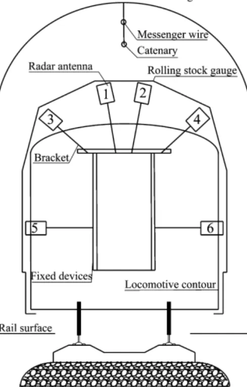
Fig. 1.Locations of the six antennas for vehicle-mounted GPR.
and nondestructiveinspection methodfortunnel healthconditions hasalways been aconcern inthe field ofthe tunnel maintenance.
2. Designandmethod 2.1. Detectionspeed
In ordertoimprovethe detectionspeed,twoproblems needtobe solved:thetrain mustoperatenormallywithouta collisionbetweentheantennaandcatenary,andthescanningrateoftheGPRsystemshouldbehighenough.
Tosolve thefirstproblem,theGPRantennamustbemounted withintherollingstock gauge,andsixsets ofantennas shouldbefixedonthetrain.InChina,foranelectricsingle-tracktunnel,thedistancefromtheantennastothetunnelwall is93–133 cm(antenna5andantenna6,inFig. 1), andthedistancefromtheantennato thetunnelvaultis175–225 cm (antenna 1 andantenna 2). Therefore,the average distancefroman air-launched antennato the liningis 159cm. Thus, a newdetectingschemethatusesanair-launchedantennaatalongdistancefromthetunnelwallwasproposed.
ThesolutiontothesecondproblemistoincreasethescanningrateoftheGPRsystem.Thescanningratemustmeetthe requirementsofthedesignedtestingspeed.Assumingthatthedesignedmeasuring-pointspacingis5cm,thesingle-channel scanningratefortheGPRshouldbeatleast4441/sifwewanttotestataspeedof80km/h.Inreality,thescanningrate ofeachchannelofthissystemis9761/s,sothehighesttestspeedof175km/hcanbereached.
2.2. Detectionefficiency
ImprovingthedetectionefficiencyrequirestheuseofamultichannelGPRsystem.Therefore,adetectingsystemwithsix channelsandsixmeasuringlineswasarranged(Fig. 1).Thissystemcandetectatunnelwithafull-sectionmode.
2.3. 300-MHzair-launchedantenna
Because the ground-coupledantenna suffersfroma “blindzone” effect,shallowanomalies such asdefects withinthe lining willbe difficultto distinguish[4,5].The depthof theblind zone extendsfromthe surface toa depth of1.5times thewavelength[6],asshowninFig. 2.The rangeoftheblind zoneisalmostequaltothenear-fieldrange.Inthisregion, thedirect-coupledwavesignalistoostrongtoexposetoboththereflectedwavefromtheliningsurfaceandthereflected signalfromthesurfacedefect.
We developeda 300-MHzair-launched antenna whose wavelength inthe air is 100 cm.A distance of1.5 times the wavelength in the air is close to the average distance between the antenna andthe tunnel wall (159 cm). This is the
Fig. 3.Radar image for shotcrete lining with rough surface.
distance that makes the air-launched antennaoperational in the far-field range.Thus, we can see the surface state and geometryofthelining,asshowninFig. 3.
Fig. 3 shows a radar image of the shotcrete lining of Yanshan tunnel. With good tunnel surrounding rock, only the sprayanchorbracingwas constructedafterblasting. Theradarimage canreflectthe geometryofthesprayanchor lining. Therefore,forthisdetectionmethod,by comparingradarimagesoverthe years,deformationsinthe tunnelliningcanbe found.
3. Systemandparameters
Thevehicle-mountedGPRsystemfortunneldetectionconsistsofsixchannels,apositioningsystem,andadata process-ingsystem.PhotographsofthesystemareshowninFig. 4.
Six-channelGPRsystem: The pulserepetition frequency ofeach channel is 500kHz, theantenna centerfrequency is 300 MHz,andthescanning rateofeachchannel is976 1/s.Eachscan has512points, andthetime windowisdesigned with60 ns/screen.Thereceiver’smaximumnoiseis0.75 mV,andtheA/Dconverterhas16bits.Thesizeoftheantennais 800 mm(length),200 mm(width),and250 mm(height).
Positioningtechnique: We adopted a positioning method combined with distance measurement and GIS correction. Namely,usingGPSandGISsystems,weautomaticallyobtainedthemileageoutsidethetunnel.Themileagesensormeasures the distance inside the tunnel. This allows the vehicle-mounted GPR system to detect the entire line atonce, which is continuousandfullyautomated.
Dataprocessingtechnique:The post-processingsoftwarecanprocess six-channeldatasimultaneouslywithafast pro-cessingspeedandsmallstoragecapacitywithoutanytransitionfiles.Themultichannelprocessingsoftwarecandisplaythe sixchannelsofdata,oranychanneldata.ThedataprocessingprocedureisshowninFig. 5.
Fig. 4.Vehicle-mounted GPR system.
Fig. 5.Flowchart of data processing.
4. Experimentalresults
The railwayvehicle-mounted GPRsystemwastestedinelectrifiedrailwaytunnelsontheBaoji–Zhongweilineandthe Xiangfan–Chongqinglinein2013.Weobtainedasignificantamountofobserveddata,whichhasbeenanalyzedandverified.
Fig. 6 showsthatthereinforcingsection(withasteelarchandejectoranchor)canbeidentified,andthatthelengthof the steelarchreinforcementsection andsteelarchintervalcan beaccurately determined.Asection oftheliningappears disconnectedandconvex.Inaddition,crescent-shapedreflectionsarevisible.ItwasverifiedafterwardthatYanjiashan tun-nel, builtinJuly1993, hadsomediseases afteroperation.The tunnelhasserious longitudinalandtransversecracks with a 25mm–40mm crackingwidthand50 mm–70mmconvexheight, aswellaslocaldropping block. From June2003to July2005,therailwayadministrationdepartmentconductedbolt-groutingreinforcement alonga140-m-lengtharchofthe tunnelthatcontaineddiseases,settingaP34ateachmeterofthesteelarch.
Fig. 6.Radar image of arch top of Yanjiashan tunnel from k96+545 to k96+578.
Fig. 7.Radar image of significant disease in left vault of Daping tunnel.
Fig. 7showsaradarimageofthevaultliningoftheDapingtunnelin2013.FromK437
+
093.
5 toK437+
118.
5,diseases were significant. Repairswere conductedin2010 by chiselinga groove inside the archlining ateach meter, inserting a permanentrailarch,andfillingitwithC20concrete.Thelength oftheserious defectsectionandtheinterval ofthesteel archintheradarimageareconsistentwiththedesign[7].Fig. 8showsaradarimageofthearchtopintheQingliangshantunnelontheBaoji–Zhongweirailwaylinein2012.The image showsthe section fromK102
+
137 toK102+
144, wherea large deformationoccurred. This area was reinforced withasteelarchandsprayanchorgrouting.Itcanbeseenfromtheradarimagethatthedeformationofthesurrounding rock appears to have a curvedcontour. After thiswas confirmed, a collapse and large deformation occurred during the constructionprocess,andreinforcementwasrequired.Part of the radar image that shows waterseepage in the vault of Guanyinxia tunnel is shown in Fig. 9. The strong reflectingimageontheliningsurfaceindicateswaterseepage.
Fig. 8.Radar image of arch top of Qingliangshan tunnel from K102+137 to K102+144.
Fig. 9.Radar image for water seepage of vault in Guanyinxia tunnel.
5. Discussionandconclusion
ComparedtoordinaryGPR,forair-launchedantennasofvehicle-mountedGPRsworkinginthefarfield[8],directwaves areseparatedfromreflectionwavesoftheliningsurface.Then,areaswithdamagedliningcanbeclearlyseen.
InsteadofusingthemethoddiscussedbyA.Wimsattetal.(2013),ourproposeddataanalysismethodadoptsan analyti-calimagingmethod.Usingthepropertiesoftheimage,someinformationcanbeeasilyidentified:integrityanddeformation, disturbanceofthesurroundingrock,steelarchesinsidethelining,andtheflatnessoftheliningsurface.
The vehicle-mounted GPRsystem, whichcan detect anentire railwaylineina shortamount oftime, provides afast, interference-freemethodforperiodicinspectionsandhealthassessmentsofexistingtunnels.
Acknowledgements
It is gratefully acknowledged that the work presented in this paper has been sponsored by the MOE’s Program for ChangjiangScholarsandInnovativeResearchTeam(IRT13092)andthe“2011CollaborativeInnovativeResearchCenter.”