Polarization and Polarization Control
Application Note 3
5215 Hellyer Ave. • San Jose, CA 95138–1001 • USA phone: (408) 284–6808 • fax: (408) 284–4824 e-mail: [email protected] • www.newfocus.com
Precise control of polarization behavior is neces-sary to obtain optimal performance from your optical components and systems. Characteristics such as reflec-tivity, insertion loss, and beam splitter ratios will be dif-ferent for difdif-ferent polarizations. Such dependencies need to be carefully accounted for in any optical design. Polarization is also important because it can be used to transmit signals and make sensitive measure-ments. Even though the light intensity may be con-stant, valuable information can be conveyed in the polarization state of an optical beam. Deciphering its polarization will tell you how the beam has been modi-fied by any of numerous material interactions (mag-netic, chemical, mechanical, etc.). Sensors and mea-surement equipment can be designed to operate on such polarization changes.
The goal of this application note is to explain how wave plates and compensators work to convert light of one polarization state to another. The first step towards understanding polarization is to think of light as an electromagnetic wave, composed of an electric
E-field and a magnetic H-field that travel together at the same velocity and in the same direction, k. Eand
Hare vector quantities, meaning they can be represent-ed by arrows that have both a magnitude (length) and a direction of orientation. Maxwell’s wave equations tell us that Eand H are connected; they are always 90° out of phase and mutually perpendicular to each other and to k. Once we know Ewe can easily determine H. Thus, we usually deal only with Eand define a wave’s polar-ization as the orientation of its E-field.
Types of Polarization
There are basically three polarization states: lin-ear, circular, and elliptical. These terms describe the path traced out by the tip of the electric-field vector as it propagates in space. The output light from a laser is typically highly polarized, that is, it consists almost entirely of one linear polarization. On the other hand, unpolarized light, such as light from a light bulb, an LED, or the sun, is a random superposition of all possi-ble polarization states.
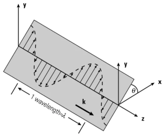
Fig. 1: A linearly polarized wave.
A snapshot in time of a linearly polarized wave is shown in Fig. 1. Notice that the spacing at which the
E-field repeats itself is one wavelength, . Although the
E-field alternates direction (sign), it stays confined to a single plane. If you could see the wave at a fixed point in zas it went by, you would observe the arrow tip oscil-lating up and down along a line. The angle of this line with respect to some reference set of axes complete-ly specifies this linear polarization state. Furthermore, we can decompose this wave into two linear wave com-ponents in the axis directions:
where =2πc/ , is the angular frequency of the wave, and kis its propagation constant, and c is the speed of light. The two cosine terms represent a traveling mono-chromatic wave. Exand Eyare orthogonal components of E. Their magnitudes are given by
For a linearly polarized wave, Exand Eyare in phase with each other.
E E E E x y = = cos , sin . θ θ λ ω E E= xcos
(
ωt− ⋅k z)
+Eycos(
ωt− ⋅k z)
, θ λ y x z k y 1 wavelength= θ λ3
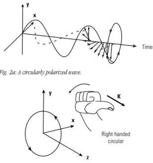
Fig. 2a: A circularly polarized wave.
Fig. 2b: Using thumb and fingers to determine handedness.
Fig. 2a sketches the evolution of a circularly polarized wave in time. You can see that the E-field vector tip forms a helix or corkscrew shape. If you stood at a fixed location, say z=0, you would observe the
Evector rotating in time, like the second hand on a watch. A circularly polarized wave can be either left-handed or right-left-handed, depending on the clockwise or counterclockwise nature of the rotation. By convention, the wave in Fig. 2a is right-handed. An easy method for remembering the convention involves using your thumb and fingers. For a right-handed circular wave, when you use your right hand and point your right thumb in the direction of propagation k, the fingers will curl in the same direction as the E-field rotation. (See Fig. 2b.) A left-handed circular wave will match with your left hand.
One way to create a circular wave is to combine two equal, orthogonal, linear waves that are 90° apart in phase. One linear wave reaches a maximum when the other goes to zero. You can see this in Fig. 2a where dashed and solid lines are used represent the two orthogonally polarized waves, and in the following expression:
.
For a circular wave, the two linear components must be
Fig. 3: Various elliptical waves for different phase delays Γ.
of the same magnitude, |Ex|=|Ey|.
If Exand Ey are not equal in magnitude, the result is an elliptically polarized wave. Elliptical waves have the same property of handedness used for circular waves. However, in order to completely characterize an elliptical wave, not only do you need to measure the ratio of major axis to minor axis (ellipticity), but you also need to relate the beam axes to some frame of ref-erence, such as a lab feature, device mount, or package marking.
Elliptical polarization is the most general case of polarization. For instance, you can think of a circle as being a special ellipse with equal major and minor axes. In general, an elliptically polarized wave will be of the form:
. Γ is a phase delay difference between the two linear wave components. Several representative elliptical waves for a range of Γvalues are shown in Fig. 3. Notice that the major and minor axes are not necessarily in the x
and ydirections. Also notice that the ellipse degenerates into a linear wave when
Γ=…-2π, -π, 0, π, 2π…(0 and 180 degrees). The polarization is circular when
Γ=…-3π/2, -π/2, π/2, 3π/2…(90 degrees) and |Ex|=|Ey|. E E= xcos
( )
ωt +Eycos(
ωt+Γ)
y x Γ=0 0<Γ<π/2 Γ=π/2 π/2<Γ<π Γ=π π<Γ<3π/2 Γ=3π/2 3π/2<Γ<2π E E= xcos( )
ωt +Eysin( )
ωt K Right-handed circular y x z y x TimeBirefringent Crystals
Since the goal of this application note is to explain how wave plates and compensators work to convert light from one polarization state to another, we must first review the properties of uniaxial crystals.
When light travels through a transparent materi-al such as a crystmateri-al, it interacts with the atoms in the lattice. Consequently, the speed of light inside the crys-tal is slower than that in a vacuum or air, typically by a factor between 1 and 3. The speed v varies inversely with the crystal’s refractive index n. That is, v=c/n. The larger the refractive index, the more the light is retarded. The amount of phase retardation (or delay) Γ that a monochromatic wave acquires from traveling through the crystal is related to its speed (refractive index), wavelength, and the path length Linside the crystal.
The simplest class of crystals are those with cubic symmetry. In a cubic crystal, all 3 crystallographic directions or axes are equivalent. nx=ny=nz, and the
crystal is optically isotropic. Regardless of how the light is polarized with respect to the crystal, it will experience the same refractive index and phase delay. Therefore, any polarized light, aside from accumulating a con-stant phase delay, remains unchanged after traveling through a defect-free, isotropic crystal. (This is also true for amorphous substances like glass.)
However, there exists another, more interesting, class of crystals that exhibit asymmetric (or anisotrop-ic) optical properties. They are known as birefringent crystals. One birefringent type is uniaxial, meaning that one crystal axis is different from the other two:
nz≠nx=ny. Common uniaxial crystals of optical quali-ty are quartz, calcite and MgF2. The single crystal axis that is unique is often called the “extraordinary” axis (or sometimes, the optic axis), and its associated refrac-tive index is labeled ne, while the other two axes are “ordinary” axes with index no.
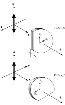
Fig. 4: Rotating a uniaxial crystal changes the phase delay (retarda-tion) for a linearly polarized wave.
For a concrete example, refer to Fig. 4. Input light that is linearly polarized along the crystal’s y axis acts as an ordinary wave and will experience refractive index no. Rotating the crystal so that the light is linear-ly polarized along the crystal’s z axis causes the light to act as an extraordinary wave which sees a refractive index ne. In these two cases, the phase delays, or opti-cal path length, will be different even though the light travels the same physical path length.
A confusing point in the terminology of uniaxial crystals is the labels: fast axis and slow axis. Whichever axis has the smallest refractive index is the fast axis. If
ne<no, as is the case with quartz, then the
extraordi-nary axis is fast and the ordiextraordi-nary axes are slow. Conversely, if ne>no, as with calcite and MgF2, then the extraordinary axis is slow, and the ordinary axes are fast. By definition, quartz is said to be a positive uniaxi-al crystuniaxi-al, whereas cuniaxi-alcite is a negative uniaxiuniaxi-al crystuniaxi-al.
ne no ne k y z z x x y k L Γ=2πnoL/ no λ Γ=2πneL/λ Γ=2p
(
Γ)
λ nL in radians .5
Wave Plates and Applications
Birefringent wave plates, or retardation plates, are extremely useful for applications where you want to synthesize and analyze light of different polarization states. For example, using a quarter-wave plate, you can convert an input beam from linear polarization to circular (or elliptical) polarization and vice versa. Using a half-wave plate, you can continuously adjust the polarization angle of a linearly-polarized beam. With just these two types of wave plates, you can build an optical isolator, a variable attenuator, or a variable-ratio beam splitter.
A wave plate is simply a cut and polished slice of uniaxial crystal, like that shown in Fig. 4. The plane of the slice contains the extraordinary (or optic) axis. An input beam that is normally incident on the wave plate will be resolved into ordinary and extraordinary axis
components, each with a different refractive index. The beam that emerges has a phase-delay difference or retardation between the axes of
If you choose the wave plate thickness Lso that the retar-dation corresponds to π/2 radians (or 90°), then it is called a quarter-wave plate. A phase shift of Γ=π/2 will convert linearly polarized light to circular and vice versa as we saw in Fig 3. Half-wave plates have πradians (or 180°) of retardation. As shown in Figure 3, a retardation of Γ=πwill flip linearly polarized light. If the incoming beam is at an angle with respect to the fast axis, the light will be flipped by 2 around the fast axis. This is especially convenient since your laser or apparatus is often too large to rotate. Quarter wave and half wave are not measures of physical thickness, rather they are in reference to a specific wavelength. Therefore, all fixed-thickness wave plates should be properly labeled with the wavelength of light they were designed for (e.g., 1/4 wave at 632.8 nm). Furthermore, since the refractive indices of all materials are strongly wave-length dependent (dispersive), it is wrong to assume a wave plate that is quarter-wave for 1060-nm light, for example, will be a half-wave plate for 530-nm light.
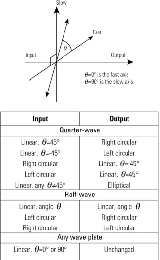
In Table 1, we summarize the most common appli-cations of wave plates. In order to follow the prescriptions in Table 1, you need to find the fast and slow axes of your wave plate and then rotate the wave plate so that the input or output polarization is at the correct angle.
In practice, it is difficult to polish a wave plate for a retardation of less than one wavelength. The crystal would be very thin, fragile and imprecise. An alterna-tive exists. Since waves repeat themselves every 2π radi-ans, any phase difference that is an integral multiple of 2πcan be subtracted out. Therefore, most fixed-thick-ness wave plates are really multiple-order wave plates. Instead of just π/2 retardation, a practical quarter-wave plate yields 2Nπ+π/2 retardation, where Nis the order of the wave plate. Multiple-order wave plates do not act exactly like zero-order wave plates, however. If you change the wavelength of your laser or light source,
θ θ Γ=2p
(
−) (
Γ)
λ ne n Lo in radians . Input Output Quarter-waveLinear, =45° Right circular
Linear, =-45° Left circular
Right circular Linear, =-45°
Left circular Linear, =45°
Linear, any ≠45° Elliptical
Half-wave
Linear, angle Linear, angle
-Left circular Right circular
Right circular Left circular
Any wave plate
Linear, =0° or θ 90° Unchanged θ θ θ θ θ θθ Slow Fast Input Output
=0° is the fast axis
=90° is the slow axis
θ θ θ
you will find that the retardation will change much more rapidly for multiple-order wave plates than for zero-order plates. Also, multiple-order retardation is 2N+1 times more sensitive to angle-tilting about nor-mal incidence. This means that a very snor-mall amount of tilt can be used to fine tune a multiple-order wave plate. But, it also means that larger errors will occur if non-parallel light rays of converging or diverging beams are used. For more precise measurements, zero-order wave plates are available. They are made by com-bining two wave plates that have retardations that differ by exactly the desired retardation. Zero-order wave plates are much less sensitive to angular, wavelength, and temperature deviations.
Soleil–Babinet and Berek’s Compensators
Fortunately, there are techniques available for making true zero-order wave plates whose retardation can be continuously adjustable. Such a variable wave plate is called a polarization compensator, and it can be used to achieve any retardation, including quarter- and half-wave, for a broad range of wavelengths. We will talk about two types of compensators: the Soleil–Babinet compensator and the Berek’s compensator.
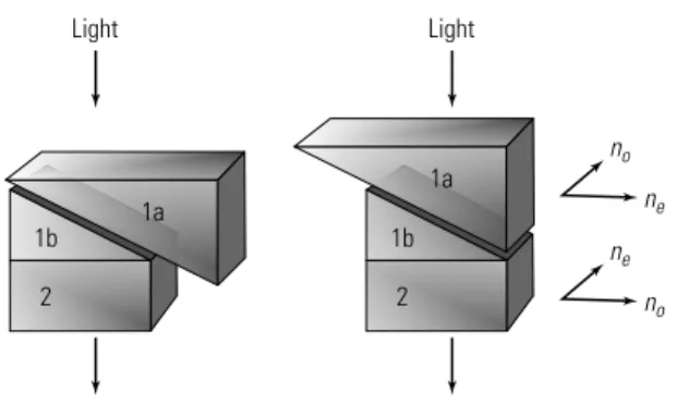
The principle behind the Soleil–Babinet is easy to understand. It effectively consists of two uniaxial plates stacked together. The extraordinary axes of the two plates are perpendicular to each other so the roles of the ordinary and extraordinary axes are reversed as the light travels through one plate and then the other. A phase difference or retardation that is accumulated in the first plate may be partially or completely canceled out by the second plate. A variable compensator is made by replacing the first plate with two complemen-tary wedges. In this manner, the total effective thickness of the first plate can be adjusted by sliding one wedge with respect to the other. (See Fig. 5.) When the first plate thickness is exactly equal to the second plate thickness, there is zero net retardation.
Although its operation is easily understood, a Soleil–Babinet compensator can be relatively expensive because it requires three pieces of carefully crafted and mounted uniaxial crystal. Another drawback of the
Soleil–Babinet is that it may be quite lossy due to reflections from the six interfaces present in the design.
Fig. 5: Soleil–Babinet compensator. Retardation is adjusted by changing the effective thickness of plate 1.
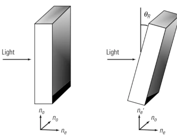
A second type of compensator, the Berek’s com-pensator, is attractive because it consists of only one plate of uniaxial crystal, thereby cutting down on the cost and optical loss while still maintaining the versa-tility of the Soleil–Babinet. The Berek’s polarization compensator, pictured in Fig. 6, consists of a single plate cut with the extraordinary axis perpendicular to the plate. When light is at normal incidence to the plate, it propagates with a velocity independent of polarization. There is no retardation because the light only experiences a refractive index no. The light is “ignorant” of the extraordinary axis. But, when the plate is tilted toward or away from the light beam, one of the axes in the plane of incidence becomes slightly extraordinary. The axis now has an effective refractive index ne′given by the formula:
Even though the amount of retardation in the Berek’s compensator depends on the degree of tilt, it has angu-lar sensitivity equal to a Soleil–Babinet compensator.
1 2 2 2 2 ′ = + ne n n R o R e cos sin . θ θ Light 1a Light 1a 1b 2 ne no no ne 1b 2
7
Fig. 6: Berek’s compensator. The extraordinary axis is perpendicular to the plate. Tilt causes birefringence and phase retardation.
Verifying Polarization States
You can obtain and verify any polarization state using a polarizer and a wave plate such as the New Focus Model 5540 Berek’s variable wave plate.
Examples
Linear-to-Linear Polarization: (Fig. 7) A half-wave plate changes the orientation of linearly polarized light by an angle of 2 , where is the angle between the input polarization and the wave plate’s fast axis. To verify that you have the correct linear polariza-tion direcpolariza-tion, orient a polarizer so that it blocks the desired polarization.
Fig. 7: A half-wave plate produces a relative phase difference of πradians between the fast- and slow-axis waves. If the incoming light is polarized at an angle αwith respect to the fast axis, the outgoing light will be rotated by 2α about the fast axis. Half-wave plates can also flip the handedness of circularly or elliptically polarized light.
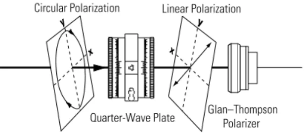
Linear-to-Circular Polarization: (Fig. 8) A quarter-wave plate converts linear polarization to cir-cular polarization. To verify that you have circir-cularly polarized light, reflect the transmitted light back through the quarter-wave plate. The reflected tion should now be orthogonal to the incident polariza-tion. A polarizing element that transmits the incident wave will therefore block the reflected beam.
Fig. 8: A quarter-wave plate introduces a relative phase shift of π/2 between the fast- and slow-axis waves. It converts linearly polarized light into elliptically polarized light. For the special case where the incident light is oriented at 45˚ with respect to either principal axis, the resulting light is circularly polarized.
Left-Hand Circular (LHC) vs. Right-Hand Circular (RHC): (Fig. 9, pg. 8) Determining hand-edness is difficult if you don’t know the orientation of the fast and slow axes of your wave plate.
With the New Focus Model 5540 Berek’s polariza-tion compensator, however, identifying the fast and slow axes is simple. The compensator works by tilting a uniaxial piece of material, whose face is perpendicular to the optic axis. The slow axis is always in the plane of incidence, perpendicular to the tilt rotation axis.
Once the orientation of the fast and slow axes is known, left- and right-hand circular polarization can be determined by using a polarizer and the compen-sator as a quarter-wave plate.
For LHC input, if the slow axis of the quarter-wave plate is along y, the output of the wave plate will be linear at -45° to x and transmitted through the polarizer as shown on pg. 8. RHC will be blocked. Rotating the wave plate or polarizer by 90° reverses this result.
Linear Polarization Circular Polarization
Quarter-Wave Plate y x y x Input Output Linear Polarization Glan–Thompson Polarizer Half-Wave Plate y x y x Linear Polarization θ θ Light Light R ne ne' no ne no no θ
Fig. 9: For LHC, if the fast axis of the quarter wave plate is aligned so that the polarization component along yis retarded by π/2 with respect to x, all the light will be transmitted through the polarizer. If x
is retarded by π/2 with respect to y, the polarizer will block the light.
Summary
For optimal performance in your experiment, precise control of the polarization of your optical beam is necessary. Wave plates can be used to convert the polarization from one state to another. When choosing a wave plate, keep in mind that single-order wave plates are less sensitive to temperature and wavelength variations and beam divergence.
References
A good reference is:
Hecht, E. 1987. Optics, 2nd ed. Reading, MA: Addison-Wesley Publishing Co.
More rigorous references are:
Born, M.; Wolf, E. 1980. Principles of Optics. Oxford: Pergammon Press.
Yariv, A.; Yeh, P. 1984. Optical Waves in Crystals.
New York: John Wiley and Sons.
Circular Polarization Glan–Thompson Polarizer Quarter-Wave Plate y x y x Linear Polarization