SX-500 and SX-510
Serial Device Server
© 2009 Silex Technology America, Inc. All rights reserved. February 2009
Silex Technology America SPECIFICALLY DISCLAIMS THE IMPLIED WARRANTIES OF MERCHANTABILITY AND FITNESS OF THIS PRODUCT FOR A PARTICULAR PURPOSE. Silex shall not be liable for any errors contained in this manual or for any damages resulting from loss of use, data, profits, or any incidental or consequential damages arising from the use of SILEX products or services. The information contained in this documentation is subject to change without notice.
Information and descriptions contained herein are the property of Silex. Such information and descriptions may not be copied, disseminated, or distributed without the express written consent of Silex. This publication is subject to change without notice.
The software embedded in this SX-500 serial device server includes the eCos operating system. eCos and certain other software programs used in the SX-500 are licensed under GNU GPL compatible Free Software Licenses (with the eCos exception clause). In compliance with these licenses, you can obtain the relevant source code at no charge by contacting Silex at [email protected].
Trademarks
ExtendView is a trademark of Silex Technology America, Inc. All other company or product names referenced in this document may be trademarks or registered trademarks of their respective owners.
Silex Technology America, Inc.
Contents Silex Page i
Contents
About This Reference Guide ...1
Safety Precautions ...1
Emissions Disclaimer ...1
Chapter 1: Introduction ...2
Chapter 2 Installing the Serial Device Server Hardware ...3
Verify Package Contents ...3
Installing the Serial Device Server ...3
Monitoring Serial Device Server Status ...5
Chapter 3 Configuring the Serial Device Server ...7
Basic Configuration Requirements ...7
Configuration Methods ...8
Using the ExtendView Utility to Configure the Serial Device Server (Ethernet Connection) ...9
First-Time IP Address Configuration ... 13
Using a Web Browser to Configure the Serial Device Server ... 15
Using the Internal Command Console to Configure the Serial Device Server ... 17
Chapter 4 Using the Serial Device Server with Your Application ... 20
Serial Port Emulator ... 20
Raw TCP connection ... 21
RFC 2217 Remote Modem Control Support ... 22
ECable Mode ... 22
Print Server Mode ... 23
FTP ... 23
Console Mode Switching ... 23
AT Commands ... 24
SNMP Traps and Email Alerts ... 24
Chapter 5 Advanced Configuration ... 26
Factory Default Settings ... 26
Restoring Factory Default Settings ... 27
Modifying TCP/IP Settings ... 27
Configuring SNMP ... 29
Configuring Serial Port Monitor Alert and Trap Configuration ... 31
Setting up Email Alerts and SNMP Traps ... 32
Using AT Modem Commands ... 33
Standard AT Commands Supported ... 33
Response Codes... 36
Using ExtendView for Bulk Configuration ... 36
Chapter 6 Troubleshooting ... 37
Chapter 7 Product Specifications ... 39
TCP Port Connections ... 40
Appendix A Advanced Security Configuration ... 41
Appendix B Console Commands ... 45
Wireless and Network Security Commands ... 45
Server Information Commands ... 52 Service Commands ... 53 String Commands ... 55 TCP/IP Commands ... 56 Firmware Update... 61 Miscellaneous Commands ... 62 Help Commands ... 62
Appendix C Firmware Update Procedures ... 63
Appendix D Safety and Regulatory Notices ... 65
Information for United States Users ... 65
Declaration of Conformity (FCC) (SX-500) ... 66
Information for Canadian Users (IC notice) (SX-500) ... 66
Information for European Users (SX-500) ... 67
Declaration of Conformity (CE) (SX-500) ... 67
Declaration of Conformity (FCC) (SX-510) ... 68
Information for Canadian Users (IC notice) (SX-510) ... 68
Appendix E Silex Contact Information ... 70
Figures
Figure 1 SX-500 (Wireless Model) and SX-510 ...2Figure 2 TCP/IP Window ... 27
Figure 3 Change Password Window ... 28
Figure 4 Advanced TCP/IP Configuration Window ... 29
Figure 5 SNMP Configuration ... 31
Tables
Table 1 Development Kit Contents ...3Table 2 Status Monitors ...5
Table 3 Factory Default Settings ... 26
Table 4 TCP/IP Settings ... 28
Table 5 TCP/IP Configuration Settings... 29
Table 6 SNMP Commands ... 30
Table 7 Port Monitor Alert Commands ... 31
Table 8 AT Commands ... 33
Table 9 Extended AT Commands ... 35
Table 10 Response Codes ... 36
Table 11 Product Specifications ... 39
Table 12 Radio Performance Specifications ... 40
Table 13 TCP Port Connections ... 40
Table 14 Network Commands ... 45
Table 15 Port Commands ... 51
Table 16 Server Information Commands ... 52
Table 17 Service Commands ... 53
Table 18 String Commands ... 55
Table 19 TCP/IP Commands ... 56
Table 20 Firmware Update ... 61
About This Reference Guide Silex Page 1
About This Reference Guide
Safety Precautions
To prevent damage to the Serial Device Server’s electronic circuit components, follow established ESD practices and procedures for handling static-sensitive devices. All ESD-sensitive components must be stored and shipped in ESD-conductive bags or bubble-wrap and labeled as such using the standardized ESD adhesive warning label.
Ethernet electrical wiring must be at least 6 feet from bare power wiring or lightning rods and associated wires, and at least 6 inches from other types of wire (antenna wires, doorbell wires, wires from transformers to neon signs), steam or hot water pipes, and heating devices.
Protectors and grounding wire placed by the service provider must not be connected to, removed, or modified by the customer.Emissions Disclaimer
Regulatory compliance information can be found in Appendix D of this manual. Final emission certification per FCC, CE and other agency requirements are the responsibility of the OEM using any printed circuit assemblies or other items used in this developer’s kit in their saleable packaged product.
Chapter 1: Introduction
The SX-500 and SX-510 Serial Device Servers provide a complete solution for connecting serial devices to 802.11 wireless or Ethernet wired networks. The following models are available: SX-500-003x Ethernet model. The SX-500 Ethernet model includes an RS-232-C device interface, 10Base-T/100Base-T Ethernet network interface, and AC power supply. SX-500-103x Wireless model. The SX-500 Wireless model includes an RS-232-C device
interface, an 802.11b/g wireless LAN interface, a 10-Base-T/100Base-T Ethernet network interface, and an AC power supply.
SX-510-103x Wireless model. The SX-510 wireless model includes an RS-232-C/RS-422/RS-485 device interface, an 802.11a/b/g wireless LAN interface with internal diversity antennas, a 10-Base-T/100Base-T Ethernet network interface, and an AC power supply.
The x in the model number designates the country or region (1 = U.S., 3 = Europe, 5 = Japan; for example, SX-500-1031 is an SX-500 wireless model for the U.S.).
Installing the Serial Device Server Silex Page 3
Chapter 2
Installing the Serial Device Server Hardware
The Serial Device Server includes most of the hardware and software components required for installation. The one item that you will need to purchase separately is a cable to connect your serial device to the Serial Device Server (this cable is not included because of the wide variety of connector types used on serial devices).
Verify Package Contents
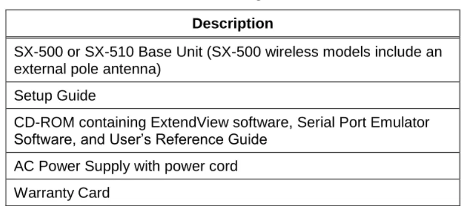
The Serial Device Server includes the components listed in Table 1. Please ensure that all materials listed are present and free from visible damage or defects before proceeding. If anything appears to be missing or damaged, please contact Silex.
Table 1 Package Contents Description
SX-500 or SX-510 Base Unit (SX-500 wireless models include an external pole antenna)
Setup Guide
CD-ROM containing ExtendView software, Serial Port Emulator Software, and User’s Reference Guide
AC Power Supply with power cord Warranty Card
Installing the Serial Device Server
Follow the steps below to install the Serial Device Server. The Serial Device Server’s factory default settings should be sufficient for most serial connections; however, some of the configuration settings may have to be changed for your particular installation.
1. Before attempting to install the Serial Device Server, make sure you have installed and set up your serial device as described in the documentation that came with the device.
2. Write down the 12-digit MAC (Media Access Code) address printed on the label located on the bottom of the Serial Device Server (for example: 004017023F96). You may need this number in order to configure the Serial Device Server.
3. If you have a wireless model, connect the antenna to the unit.
4. Connect the Serial Device Server to your serial device. If you are using RS-232, you may use standard PC cabling (you should normally use a null modem crossover cable). The 9-pin connector pinouts and cabling are as follows:
RS-232 connector pinouts and cabling
If you are using RS-422 or RS-485 in full-duplex or half-duplex modes, you will need a special cable. In addition, if the Silex Serial device Server is the last one in a chain, then a 120-ohm resistor should be placed between pins 2 and 6 (for full-duplex mode) or pins 4 and 5 (for half-duplex mode).
IMPORTANT: IF YOU ARE USING RS-422, RS-485, OR RS-485 HALF-DUPLEX, YOU MUST SET THE SERIAL PORT LINE MODE AS DESCRIBED IN CHAPTER 3 OF THIS MANUAL.
The RS-422 and RS-485 pinouts and cabling are shown in the following diagrams:
RS-422/485 full-duplex connector pinouts and cabling
RS-485 half-duplex connector pinouts and cabling
IMPORTANT NOTE: THE SX-510 RS-422/RS-485 INTERFACE HAS NOT BEEN TESTED FOR COMPLIANCE WITH IEC 60601-1-2:2001/EN60601-1-2 MEDICAL EMC OR ANSI/IEEE Std. C95.1-1999, RSS-102 SAR STANDARDS. THEREFORE RS-422/485 SHOULD NOT BE ENABLED IF YOU REQUIRE COMPLIANCE WITH ANY OF THESE STANDARDS.
Installing the Serial Device Server Silex Page 5
5. Plug the Serial Device Server power supply adapter into a suitable AC receptacle, and then plug the power supply cable into the Serial Device Server. Alternatively, you can use pin 9 on the 9-pin connector to provide power to the Serial Device Server (1 amp @ +5V is required). The Serial Device Server will run through a sequence of power-up diagnostics for a few seconds.
If the Serial Device Server is operating properly, the LEDs will blink momentarily and then go out, the yellow and green LEDs will illuminate if the wireless network is active, and the orange LED will illuminate, indicating the device is receiving power.
The unit powers up in the Normal mode, which provides for connection from the network to device(s) connected to the serial port of the Serial Device Server.
If the orange LED blinks continuously in a regular pattern, a problem exists. If this is the case, try powering the unit OFF and then ON again.
.
6. Connect the Serial Device Server to your network through a switch or hub using a category 5 (CAT5) Ethernet cable. Serial Device Server wireless models automatically detect the presence of this cable, and will switch off the wireless networking functionality as long as the cable is plugged in.
7. The Serial Device Server’s IP address must be configured before a network connection is available.
If your network offers DHCP (Dynamic Host Configuration Protocol), the Serial Device Server will automatically search for a DCHP server upon power up and obtain an IP address. If your network does not offer DHCP, a static (fixed) IP address must be assigned (see your system administrator for assistance). If you use DHCP, make sure that the length of the DHCP lease is adequate so that the IP address of the Serial Device Server does not change.
Monitoring Serial Device Server Status
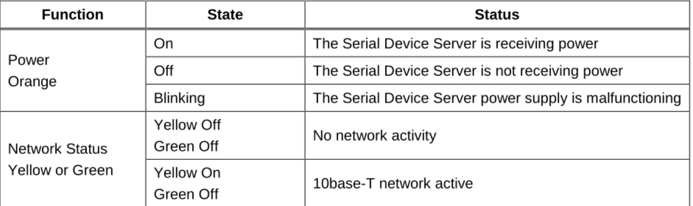
You can monitor the Serial Device Server status using the yellow, green and orange LED status indicators on the monitor. Table 2 defines the default functions of the LED status indicators.
Table 2 Status Monitors
Function State Status
Power Orange
On The Serial Device Server is receiving power Off The Serial Device Server is not receiving power
Blinking The Serial Device Server power supply is malfunctioning
Network Status Yellow or Green
Yellow Off
Green Off No network activity Yellow On
Green Off 10base-T network active
NOTE: Pin 9 is normally configured for supplying +5V from an external power source in lieu of using the AC power supply adapter. If you wish to use this pin as the Ring Indicator (RI) modem signal on the SX-500 (not available on the SX-510), open the enclosure and move the jumper on connector JP1 onto pins 2 and 3 of this connector.
NOTE: SILEX RECOMMENDS USING A HARDWIRED ETHERNET CONNECTION FOR CONFIGURING WIRELESS SERIAL DEVICE SERVERS. If you have a wireless Serial Device Server model and cannot use an Ethernet connection, refer to
step 4 in the First Time IP Address Configuration section of this chapter for instructions on how to set up the Serial
Function State Status
Yellow Blinking
Green Off 10base-T network data received Yellow Off
Green On 100base-TX network active Yellow Off
Green Blinking 100base-TX network data received Yellow On
Green On Wireless network active, if WLAN model Yellow Blinking
Configuring the Serial Device Server Silex Page 7
Chapter 3
Configuring the Serial Device Server
This chapter describes the methods for configuring the basic settings of the Serial Device Server,
including the IP address, serial port settings, and wireless security. The Serial Device Server also has an extensive range of advanced configuration capabilities that are described in Chapter 5, Appendix A, and Appendix B. The Serial Device Server configuration should be done by a network administrator or another person with technical knowledge of TCP/IP networking and serial communications.
Basic Configuration Requirements
In order to use the Serial Device Server, the following basic parameters must be configured:
TCP/IP Settings:
IP Address Subnet Mask Router Address
Note: The TCP/IP settings can be automatically configured using DHCP.
Wireless Configuration Settings:
SSID
Mode (Infrastructure or Ad Hoc)
Channel (required only if using Ad Hoc mode)
Security Settings:
Wireless Encryption Mode (WPA2, WPA, WPA2-WPA, WEP) Wireless Encryption Settings
Wireless Authentication Mode (WPA-PSK, Open System, Shared Key, TTLS, TLS, LEAP, PEAP, EAP-FAST)
Wired Authentication Mode (TTLS, TLS, PEAP, EAP-FAST) Authentication Settings
Note: There are numerous possible encryption and authentication settings, and every network can have different settings. Please refer to Appendix A for a detailed summary of these settings.
Serial Port Settings (must match the settings of the attached serial device):
Baud Rate (Speed) Parity
Character Size Flow Control
Line Mode (RS-232, RS-422, RS-485 full-duplex, RS-485 half-duplex; RS-422 and RS-485 are supported on the SX-510 only)
In addition to the above parameters, the Serial Device Server allows you to configure numerous other capabilities. These other capabilities provide you with the unparalleled flexibility to use the Serial Device Server on virtually any 802.11 or Ethernet network with a wide range of serial devices.
Configuration Methods
There are three ways to configure the Serial Device Server:
ExtendView. ExtendView is a simple Graphical User Interface configuration program for
Windows. In addition to setting up the initial Serial Device Server configuration, ExtendView also has the advantage of allowing you to perform bulk configuration of multiple Serial Device Servers simultaneously.
Internal Web Pages (HTTP). You can use any standard web browser to access the Serial Device
Server internal web pages. These web pages provide an easy-to-use graphical interface for configuring the Serial Device Server. In order to use the internal web pages for the first time, you must assign the Serial Device Server IP address using some other method (for example, DHCP or arp/ping). This initial IP address assignment need only be done one time.
Internal Command Console. The internal command console provides a sophisticated command
line interface for advanced users to configure the Serial Device Server. It can be accessed by connecting a serial cable to the serial port and using console mode switching as descried in chapter 4. Once the IP address has been assigned, the internal command console can also be accessed via TELNET, or via ExtendView and the internal web pages.
If you have a Serial Device Server wireless model, Silex recommends that you temporarily plug the Serial Device into a wired Ethernet network during the configuration process. Although it is possible to configure the Serial Device Server with a completely wireless setup, it is much simpler to perform the process using a wired Ethernet connection. This is primarily because the wireless security on most wireless networks prevents the addition of a new wireless device unless all security parameters are first entered into that device. As a result, you must set up a temporary dedicated ad hoc wireless network in order to configure the Serial Device Server in a completely wireless environment (refer to the step 4 in
the First Time IP Address Configuration section of this chapter for instructions on how to set up the Serial
Device Server using a completely wireless Ad Hoc environment).
Configuring the Serial Device Server using each of the above methods is described in the following sections of this chapter.
Configuring the Serial Device Server Silex Page 9
Using the ExtendView Utility to Configure the Serial Device Server
(Ethernet Connection)
The ExtendView Utility is the easiest way to initially configure the Serial Device Server from a Windows PC because it allows you to directly set the IP address into an unconfigured Serial Device Server, and it allows you to view the IP addresses of all of the Serial Device Servers on your network. It has limited capabilities for configuring 802.1X authentication, but it can be used in conjunction with either the internal web pages or the internal command console for complete configuration capabilities.
ExtendView is a component of the CD-ROM that is included with the Serial Device Server, or it can be downloaded from the Silex website. To install ExtendView, simply follow the on-screen installation instructions. The Serial Device Server configuration procedure is as follows (please note that the screens may be slightly different than shown, depending on the Serial Device Server model and the firmware and software revision levels).
1. Start the ExtendView Utility by clicking on
Start, Programs, silex technology, ExtendView, and then ExtendView.
2. When the Welcome screen appears, click on
Next, choose any name for your View Name, select Automatically create a view with default settings (or configure the view to your preferences), and then click Finish.
NOTE: Skip this section if you do not have a Windows PC or if you do not have an Ethernet connection available for configuring your Serial Device Server wireless model.
3. Right-click on the Serial Device Server that you want to configure from the displayed list, and then left-click on Configuration. The default Serial Device Server name is
SLXxxxxxx (where xxxxxx is the last six digits of the MAC address from the label that is affixed to the Serial Device Server).
4. If you do not have a DHCP server, you will be asked to manually enter an IP address (if you are not sure what IP address to enter, ask your network administrator). Click OK when you are finished.
5. The Server Configuration window will appear. Check the IP address setting to make sure it is correct. If necessary, change the Subnet Mask and Gateway. If you have a WINS server, enter its address or click Use DHCP to Locate WINS Server. If desired, you can configure advanced TCP/IP settings by clicking the Advanced TCP/IP button (refer to Chapter 5 for information). This advanced configuration can be done at a later time, however.
NOTE: If you are using DHCP on your network, the SX-500 should have acquired valid IP settings at this point and no further configuration is necessary. However, for some installations, a static IP address is preferred. If your DHCP server does not allow the SX-500 to keep its assigned IP address permanently, then you must manually assign an IP address. In this case, use a static IP address outside the range reserved for DHCP (see your DHCP server documentation for details). To assign a
static IP address, select Set Permanent as the IP Address
Resolution, and assign a valid static IP address for your
Configuring the Serial Device Server Silex Page 11 6. Click the Wireless tab to configure the 802.11
wireless settings (for wireless models only; skip to the next section if you have a wired model). To operate on an 802.11 network, the Serial Device Server configuration must be configured with the wireless configuration and security parameters necessary for the Serial Device Server to communicate over your wireless network (check with your network administrator if you do not know these parameters).
Select either Infrastructure (if you are using an access point) or Ad Hoc (point-to-point) as the wireless mode
Enter the SSID for your network If you are using Ad Hoc, select
the RF channel (not required for infrastructure)
The other parameters on this tab do not normally need to be changed (refer to Chapter 5 for information on advanced configuration). Now click the Configure Wireless Security
button to configure the wireless security parameters.
7. If you are using WPA2-PSK, select WPA2 as the Encryption Mode and select PSK as the Authentication Type. If you are using WPA-PSK, select WPA as the encryption mode and select PSK as the Authentication Type. For both WPA2-PSK and WPA-PSK you must enter the Pre-Shared Key for your network and select whether you want a Group Key. Note that it is not necessary to enter a User ID or password.
If you are using WEP, select 128-bit or 64-bit as the Encryption Mode and Open Systems or Shared Key as the Authentication Type. Enter the WEP keys in hexadecimal format, and select the transmit key (Key Selection). ExtendView does not fully support configuration of the 802.1X EAP types, so Silex recommends using the internal web pages or internal command console for 802.1X configuration as described later in this chapter.
Click OK to return to the Server Configuration window, and then click the I/O port tab to configure the serial port.
8. You do not need to change any of the settings in this window. Click the Serial Settings
button to configure the serial port.
9. Configure the serial port settings so that they match the settings on your device. For example, if your device is set for 9600bps, odd parity, and XON/XOFF flow control, you must change the settings on the Serial Device Server to these settings.
If are using either RS-422 or RS-485 (SX-510 only), select 422 or 485 as the Mode. Select Half as the Duplex type if you are using RS-485 half-duplex.
Click OK when you are finished to return to the Server Configuration window and then click OK again.
10. Click OK to save your changes and reset the Serial Device Server. If you are configuring a Serial Device Server wireless model, unplug the Ethernet cable. You can now use the Serial Device Server on your network. You may skip the remaining sections of this chapter, although this information is useful for future reference.
Configuring the Serial Device Server Silex Page 13
First-Time IP Address Configuration
If you are configuring the Serial Device Server from a non-Windows computer or if you cannot use an Ethernet connection, you must first configure the Serial Device Server IP address. Note that it is only necessary to perform this task one time -- once the address has been configured, the Serial Device Server can be accessed from any computer on the network that has the appropriate privileges. The steps are as follows:
1. If your network has a DHCP server and you can use an Ethernet connection to the Serial Device Server:
a. Make sure your PC is connected and has access to your network.
b. Connect an Ethernet cable from your network hub to the Serial Device Server (if you have a wireless Serial Device Server and do not have hardwired capabilities, then you must go to Step 4 below for setup instructions).
c. Power on the Serial Device Server.
d. The administration program on most DHCP servers logs the IP address and MAC address of each DHCP client. The MAC address of the Serial Device Server can be found on the label affixed to the unit. If your DHCP server has logged this information, write down the IP address of the Serial Device Server for future reference. You are now ready to configure the Serial Device Server (skip the remainder of this section).
e. If your DHCP server does not provide client information or if you do not have access to the DHCP server, then you can get the IP address by connecting a serial device such as a printer, a Windows PC running HyperTerminal, or another serial device capable of printing ASCII characters to the serial port the Serial Device Server). Your serial device must be set at 115.2Kbps, 8-bit character size, and no parity.
f. With the serial device and Serial Device Server switched on and ready, press the Reset
pushbutton on the Serial Device Server. This will cause the Serial Device Server configuration data to be sent to the connected serial device. The serial device should display or print the current IP address assigned to the Serial Device Server by your network DHCP service. Write down this address for future reference. You are now ready to configure the Serial Device Server (skip the remainder of this section).
2. If you can connect the Serial Device Server via Ethernet but do not have a DHCP server, then you must use the following procedure for the first-time IP configuration of the Serial Device Server.
a. Make sure your PC is connected and has access to your network
b. Connect an Ethernet cable from your network hub to the Serial Device Server. The Serial Device Server must be on the same network segment as the PC (that is, there can be no router between the Serial Device Server and the PC).
c. From the Windows Command Prompt (MS-DOS Prompt), the Mac OS X Terminal Utility, or the UNIX/Linux command line, enter the command
arp –s ipaddress macaddress ping ipaddress
Where ipaddress is the desired IP address of the Serial Device Server and
macaddress is the MAC address of the Serial Device Server (found on the label
affixed to the Serial Device Server). For example:
arp –s 192.168.5.53 00:40:17:00:00:01 ping 192.168.5.53
Note that Windows systems use the format xx-xx-xx-xx-xx-xx for the MAC address (for example, 00-0017-00-00-01).
You will see a reply from the Serial Device Server with the number of bytes and other information if the address was successfully set.
If you get an error message or no response, then the IP address was not set. If this is the case, the Serial Device Server may not be at its default configuration. To reset the Serial Device Server to its default settings, hold down the reset pushbutton for more than five seconds.
d. You are now ready to configure the Serial Device Server (skip the remainder of this section).
3. If you are using a wireless connection for the first-time configuration of the Serial Device Server, you must set up a temporary ad hoc wireless connection as described in the following steps. Please note that because this is a fairly complex process, we do not recommend it unless it is not possible to use a wired connection.
a. Disconnect your PC and the Serial Device Server from your network, and temporarily set the PC settings as follows:
IP address: 192.0.0.191
Wireless Mode: Ad Hoc (sometimes referred to as Peer-to-Peer) Channel: 11
SSID (or wireless network name): serserv
b. Power on the PC and the Serial Device Server. You can connect to the Serial Device Server by specifying its default IP address of 192.0.0.192 using a web browser as described in the next section. When you have connected to the Serial Device Server, you must then change the IP address and enter the required wireless networking parameters using either the web browser interface or the internal command console (see next two sections) for operation on your wireless network.
c. After you complete the entire Serial Device Server configuration process, you must set your PC back to its original network settings.
Configuring the Serial Device Server Silex Page 15
Using a Web Browser to Configure the Serial Device Server
After you have entered an IP address into the Serial Device Server, you can use any standard web browser to access the internal web pages for configuring the Serial Device Server. Simply specify the IP address of the Serial Device Server in your browser and then follow the steps below:
1. When you have connected to the Serial Device Server, you will get the Server Info page. Click Login on the left side of the screen.
2. Enter the password accessand press
Submit.
3. You will return to the Server Info page, but new options will be listed on the left side of the screen. Click on TCP/IP.
IMPORTANT: You must click the Submit button when you have finished configuring an internal web page. If you do not do
this, your changes will not be saved.
You may skip this section if you have completely configured the SX-500 using ExtendView. However, if you have advanced configuration requirements, such as 802.1X EAP configuration, then you may need to use the internal web pages as described in this section because ExtendView does not support these capabilities.
If you used DHCP, verify that the IP address is correctly set. If you used the default 192.0.0.192 IP address, you MUST change it to a new valid IP address. If necessary, change the Subnet Mask and Gateway. It is generally not necessary to change the other parameters on this page (refer to Chapter 5 for advanced configuration information. Note that on-line help information is available on every configuration page.
Click the Submit button at the bottom of the window (you may need to scroll) to save your changes.
4. Click Wireless on the left side of the screen to configure the 802.11a/b/g wireless settings (for WLAN models only; skip to the next section if you have an Ethernet model). To operate on an 802.11a/b/g network, the Serial Device Server configuration must be
configured with the wireless configuration and security parameters required to allow the Serial Device Server to communicate over your wireless network (check with your network administrator if you do not know these parameters).
Select either Infrastructure (if you are using an access point) or Ad Hoc (point-to-point) as the wireless mode Enter the SSID for your network If you are using Ad Hoc, select the RF
channel (not required for infrastructure) The other parameters on this page do not normally need to be changed (refer to Chapter 5 for information on advanced configuration). Click the Submit button at the bottom of the window (you may need to scroll) to save your changes.
Now click Configure Network Security to configure the wireless security parameters.
NOTE: If you are using DHCP on your network, the SX-500 should have acquired valid IP settings at this point and no further configuration is necessary. However, for some installations, a static IP address is preferred. If your DHCP server does not allow the SX-500 to keep its assigned IP address permanently, then you must manually assign an IP address. In this case, use a static IP address outside the range reserved for DHCP (see your DHCP server documentation for details). To
assign a static IP address, select Set Permanent as the
IP Address Resolution, and assign a valid static IP
address for your network. Click on OK to save the new
Configuring the Serial Device Server Silex Page 17 5. Select the appropriate wireless encryption
mode and enter the required settings (check with your network administrator for the proper settings if you do not know them). Appendix A lists the possible encryption settings.
Click the Submit button at the bottom of the window (you may need to scroll) to save your changes.
Now click I/O Port on the left side of the screen to configure the serial port.
6. Configure the serial port settings so that they match the settings on your device. For example, if your device is set for 9600bps, odd parity, and XON/XOFF flow control, you must change the settings on the Serial Device Server to these settings.
If you are using RS-422 or RS-485 (SX-510 only), select 422, 485, or 485HD (half-duplex) as the mode.
Click the Submit button at the bottom of the window (you may need to scroll) to save your changes.
When you have finished with all your configuration changes, you must restart the Serial Device Server for these changes to take effect.
You can skip the remainder of this chapter.
Using the Internal Command Console to Configure the Serial Device
Server
The Internal Command Console is a command line oriented method for configuring the Serial Device Server. It provides more comprehensive capabilities than either ExtendView or the Internal Web Pages, but is not as easy to use. Advanced users may prefer to use this method because it is concise, fast, and powerful.
To use the Internal Command Console:
1. To access the Internal Command Console, enter the following command from the Windows Command Prompt (MS-DOS Prompt), Mac OS X Terminal Utility, or UNIX/Linux command line:
You may skip this section if you have completely configured the SX-500 using ExtendView or the SX-500 Internal Web Pages.
telnet aa.bb.cc.dd
where aa.bb.cc.dd is the IP address of the Serial Device Server (for example, telnet 192.168.5.6).
2. Press <ENTER> and then enter the password access at the # prompt. Press <ENTER> at the
Enter Username> prompt. When you see the Local> prompt, you can enter console commands.
3. If you used the default 192.0.0.192 IP address to connect to the Serial Device Server, you MUST change it to a new valid IP address. If necessary, you must also change the Subnet Mask and Router (Gateway). The commands are as follows:
SET IP ADDRESS aa.bb.cc.dd SET IP SUBNET aa.bb.cc.dd SET IP ROUTER aa.bb.cc.dd
where aa.bb.cc.dd is the IP address of the Serial Device Server. You can use the command SHOW IP to verify the IP address settings.
4. Enter the basic wireless settings as follows:
SET NW SSID <name> [where <name> is the SSID for your network] SET NW MODE <mode> [where mode is INFRASTRUCTURE or
AD-HOC]
SET NW CHANNEL n [where n is 1 to 11; this is only required for AD-HOC MODE]
5. Use the appropriate SET NW command to set wireless encryption mode and authentication type (check with your network administrator for the proper settings if you do not know them):
SET NW ENC <mode> [sets encryption mode, where <mode> is WPA, WPA2, 64, 128, or WPA2-WPA]
SET NW AUTHTYPE <type> [sets authentication type, where <type> is OPEN, SHARED, TTLS, PEAP, WPA-PSK, LEAP, TLS, or FAST].
For WPA2-PSK or WPA, enter the command:
SET NW WPAPSK <psk> [sets pre-shared key for WPA2 or WPA, where <psk> is the key]
SET NW WPAGROUP <state> [enables or disables WPA group key mode, where <state> is ENABLED or DISABLED; default is DISABLED]
For WEP (WEP64 or WEP128), use the following commands:
SET NW KEYVAL <key> [Sets WEP key, where <key> is 10 hex
characters for WEP64 or 26 hex characters for WEP128]
SET NW KEY# n [sets the number of the WEP key that will be used as the transmit key, where n=1 to 4; default value is 1]
Configuring 802.1X EAP authentication can be complex. Please refer to Appendix A and/or Appendix B for details of the required commands.
Configuring the Serial Device Server Silex Page 19 6. To set the serial port, enter the following commands:
SET PORT S1 SPEED <baudrate> [where <baudrate> is 300 to 921600] SET PORT S1 PARITY <parity> [where <parity> is ODD, EVEN, MARK, or
SPACE]
SET PORT S1 SIZE <databits> [where <databits> is 7 or 8]
SET PORT S1 FLOW <flowcontrol> [where <flowcontrol> is NONE, XON/XOFF, CTS, or DSR]
SET PORT S1 MODE <line mode> [where <line mode> is 232, 422, 485, or 485HD; this command only applies to the SX-510] The console commands are summarized in Appendix B of this manual.
7. When you have finished entering commands type: INIT
EXIT
These commands will save the configuration and restart the unit. You are now ready to use the Serial Device Server.
EXIT
8. Note that you can also access the Internal Command Console in the following ways:
Internal Web Pages. Use a web browser to connect to the Serial Device Server internal
web pages as described earlier in this chapter. After you have logged in, click Admin on the left side of the screen, and then click Console. You can now enter console
commands (you must click Enter after each command).
ExtendView. Select the desired Serial Device Server from the ExtendView main menu.
Click Tools on the menu bar, and then click Telnet Session. Press <ENTER> and then enter the password access at the # prompt. Press <ENTER> at the Enter Username> prompt and you are now ready to enter console commands.
IMPORTANT: The console command EXIT must always be used in order to save the changes you made with the internal command Console.
Chapter 4
Using the Serial Device Server with Your Application
The Serial Device Server includes a number of capabilities that enable it to be used in a wide range of applications. These capabilities include:1. Serial Port Emulator (SPE) software 2. Raw TCP connection
3. RFC2217 4. ECable Mode 5. Print Server mode 6. FTP
7. Console mode switching 8. AT commands
9. SNMP traps and Email alerts
These methods are described in the following sections.
Serial Port Emulator
The Serial Port Emulator (SPE) software emulates a standard Windows COM port. That is, it creates a virtual COM port that functions exactly like the Windows COM1 and COM2 serial ports, except that the I/O actually goes out over the Ethernet or WLAN to the Serial Device Server and to the serial device that is connected to the Serial Device Server. As a result, any application program that uses a standard Windows COM port can also use the Serial Port Emulator. The SPE is therefore especially useful if you have existing programs that use Windows COM ports.
The SPE software is a component on the CD-ROM that is included with the Serial Device Server, or it can be downloaded from the Silex website. To install it, double click on the installer icon and follow the installation instructions. When the installation is complete, you can run the SPE software by clicking Start -> Programs -> Silex technology -> Serial Port Emulator -> Serial Port Emulator.
Using the Serial Device Server Silex Page 21 After the Serial Port Emulator software has started, you will see a list of all the configured Serial Device Servers on the network. Right click on the name of the Serial Device Server that you want the virtual COM port to connect to (the default name is SLXxxxxxx, where xxxxxx is the last six digits of the Serial Device Server MAC address), and then click Virtual Port. You will be asked to select the name of the virtual COM port (for example, COM3).
Click OK after you have selected the name, and you now ready to use the virtual COM port.
Using virtual COM port is identical to using a normal COM port. For example, if you configure a virtual COM port called COM3, this port will show up as one of the available serial ports when you use the Windows HyperTerminal Accessory program.
Raw TCP connection
You can communicate directly from your application program to the Serial Device Server using a raw TCP connection. This is done by opening a TCP port on the Serial Device Server and then sending and receiving data to this port via a socket or equivalent API. This method is more efficient than using the Serial Port Emulator, and does not require any additional software to be installed on your computer. If you are using a raw TCP connection, the default TCP port number (you can use any or all of these port numbers) for normal connections. If you want to be able to access your device’s modem control signals from your computer system, then the TCP port number is 9200 (this enables RFC 2217 support). You can change the port number, if desired, by modifying one of the Serial Device Server services. To change the TCP port number:
1. Connect to the Serial Device Server with a web browser (see chapter 3 for instructions on doing this);
2. After you have logged in, click I/O Services on the left side of the page.
3. Click on the service name that you want to change (any one of the services is OK, provided that you are not using the existing TCP port number of that service for a different application). 4. Change the Raw TCP Port to the desired number (must be greater than 1023).
5. Click Submit to save your change.
You can test this connection by using the TELNET utility from the Windows Command Prompt (MS-DOS prompt), Mac OS X Terminal Utility, or UNIX/Linux command line as follows:
where ipaddress is the IP address of the Serial Device Server and portnumber is the Serial Device Server TCP port number. For example:
telnet 192.168.5.53 9100
In this example, if you have a serial printer or other device capable of displaying ASCII characters
connected to the Serial Device Server serial port, then every character you type should be printed on that serial device (buffered serial devices may need you to type a control character such as a formfeed (CONTROL-L) before the characters are printed).
RFC 2217 Remote Modem Control Support
RFC 2217 allows you to access your device’s modem control signals over the network. It is especially useful for migrating applications that use modem controls from a direct serial connection to a serial device server network connection. You can utilize RFC 2217 from the Silex Serial Port Emulator software (see below), or by connecting to TCP port 9200 from your application program.
ECable Mode
Normally, it is up the computer to initiate a connection to the Serial Device Server. For some applications, it is desirable for the Serial Device Server to initiate the connection to the computer. The Serial Device Server supports this capability through its ECable feature.
To set ECable mode, use a web browser to access the Serial Device Server internal web pages (see chapter 3 for instructions on using the internal web pages). After you have logged in, click I/O port on the left side of the screen.
You can now enable ECable mode and set the required parameters. 1. Enable ECable mode by clicking the radio button.
2. Enter the address (Destination Address) of the computer or other device that will be communicating with the Serial Device Server)
3. Enter the TCP port number (Destination Port) used by the destination device for communicating with the Serial Device Server (must be greater 1023).
4. If desired, change the ECable Connection Attempt Time. This specifies the time interval between connection attempts. For example, by default the Serial Device Server will try once every 30 seconds to make a connection to the destination device; if it fails to make this connection, it will wait 30 seconds before attempting again. Changing this interval will reduce or increase the amount of network traffic.
5. It is also possible to use UDP instead of TCP for communicating to and from the Serial Device Server. If you wish to use UDP, then:
Using the Serial Device Server Silex Page 23 b. Enter the UDP port number (Destination Port) used by the destination device to
communicate with the Serial Device Server. This number must be a valid port on the destination device (check the documentation for that device to determine the valid port numbers).
c. Enter the UDP port number (Local Port) used by the Serial Device Server to
communicate with the destination device. This number must be greater than 1023, but is otherwise arbitrary.
Print Server Mode
You can use the Serial Device Server as a standard TCP/IP print server, which is very useful if you are connecting the Serial Device Server to a serial printer. The Serial Device Server supports the following standards:
lpr/lpd. This is one of the most popular ways to print on a TCP/IP network. Check your
computer’s documentation to determine how to set up an lpr print queue. Usually this simply involves specifying the IP address of the Serial Device Server as the printer’s address or host name. Some implementations require a queue name; this name is the name of any of the Serial Device Server services. To see the names of the Serial Device Server services, connect to the Serial Device Server with a web browser (see chapter 3 for instructions on doing this); after you have logged in, click I/O Services on the left side of the page.
Port 9100. This method is used to set up a Windows Standard TCP/IP port or for
compatibility with software that supports the HP JetDirect Print Server (for example, HP Web JetAdmin). To use this capability on Windows with the Add Printer Wizard, specify that you want to use a Local printer attached to this computer (not a network printer), and then select Create a new port, specifying Standard TCP/IP Port as the type of port. It is also possible to change the TCP port number from the default 9100 for compatibility with other printer manufacturer’s software. To do this, refer to the instructions in the Raw
TCP Connection section of this chapter.
FTP
The Serial Device Server supports FTP binary or ASCII communications. This can be used, for example, to send the contents of a file from a PC to a device connected to the Serial Device Server using the FTP protocol. To use FTP, simply enter the standard FTP command from your PC with the IP address of the Serial Device Server (for example, ftp 192.168.5.50). When the connection is made, enter any username and password. You can then use the standard FTP put command to send the file from the PC to the device connected to the serial port on the Serial Device Server.
Console Mode Switching
The Serial Device Server allows you to dynamically switch the operation of the serial port from normal mode to console mode. This allows your device to control the operation of the Serial Device Server by sending console commands (see chapter 6 and Appendix B for a description of the console commands). Note that console mode can only be entered when there is no connection to a remote host.
To switch the serial port to console mode, you must first define a console string. When the Serial Device Server receives this string on the serial port, it will automatically switch the port to console mode. To define the console string, use a web browser to access the Serial Device Server internal web pages.
After you log in, click I/O Port, and then select the desired port (S1 for the serial port). When you get the
I/O Port Settings page, enter any desired character string (for example, xyz) as the Console Mode String. Click Submit to save your string, and then restart the Serial Device Server to make the change take effect.
Alternatively, you can define the console mode string using the console command from TELNET as shown in the following example:
SET PORT S1 CONSTR xyz
Once you are connected in console mode, you can send any of the console commands listed in Chapter 5. Be sure to terminate each console command with a carriage return (ASCII 13) or linefeed (ASCII 10) character.
When you are finished using the console, you can return to the normal port operation by sending the command EXIT followed by a return or linefeed character.
AT Commands
The Serial Device Server allows you to control the serial port using standard AT modem commands. This allows you, for instance, to initiate connections and to switch between console mode and data mode by sending the appropriate commands. These capabilities are similar to the console mode switching described in the previous section, but have the following advantages:
Your device can initiate a network connection
Operation is compatible with software that uses the AT command set
The drawback, however, is that there is a slight delay when switching from data mode to AT command mode. To use the AT commands, you must first enable this capability using the I/O Port Settings internal web page for the serial port (S1). Change the Port Filter setting to AT in order to enable AT mode on that port and press the Submit button to save the change. You must restart the Serial Device Server to make the change take effect.
You can also use the console to enable the AT capabilities. For example, the command SET PORT S1 FILTER AT
enables AT capabilities on the serial port.
Note: If you use the AT commands on the serial port, you cannot use SNMP traps or Email alerts for that port.
The AT commands are described in detail in Chapter 5.
SNMP Traps and Email Alerts
The Serial Device Server allows the user to define various alert conditions based on data received by the serial port. For example, you could cause an alert to occur if a certain user-defined string of characters is received on the serial port. When an alert occurs, it can be sent as an SNMP trap and/or as an Email message.
Chapter 5
Advanced Configuration
The Serial Device Server Serial Device Server is equipped with a default configuration that works with most serial-to-Ethernet connections. You can modify the settings to suit your installation requirements. The web browser interface is the recommended method for setting advanced configuration parameters (some of the advanced configuration parameters are not accessible via ExtendView). However, regardless of the method to access the configuration parameters, the method for modifying the parameters is virtually identical.
Factory Default Settings
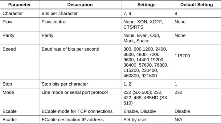
Table 3 displays the configuration parameter descriptions and settings with the default settings indicated in a separate column.
Table 3 Factory Default Settings
Parameter Description Settings Default Setting
Character Bits per character 7, 8 8
Flow Flow control None, XON, XOFF,
CTS/RTS
None
Parity Parity None, Even, Odd,
Mark, Space
None Speed Baud rate of bits per second 300, 600,1200, 2400,
3600, 4800, 7200, 9600, 14400,19200, 38400, 57600, 76800, 115200, 230400, 460800, 921600 115200
Stop Stop bits per character 1, 2 1
Mode Line mode or serial port protocol 232 (SX-500); 232, 422, 485, 485HD (SX-510)
232
Ecable ECable mode for TCP connections Enable, Disable Disable
Advanced Configuration Silex Page 27
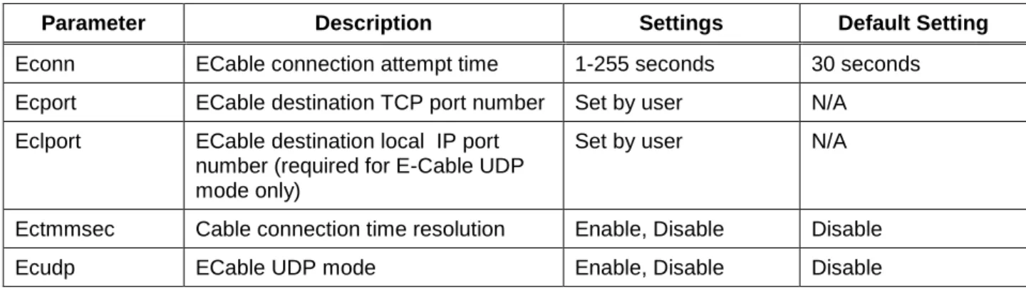
Parameter Description Settings Default Setting
Econn ECable connection attempt time 1-255 seconds 30 seconds Ecport ECable destination TCP port number Set by user N/A
Eclport ECable destination local IP port number (required for E-Cable UDP mode only)
Set by user N/A
Ectmmsec Cable connection time resolution Enable, Disable Disable
Ecudp ECable UDP mode Enable, Disable Disable
Restoring Factory Default Settings
The factory default settings can be restored at any time To do this, hold down the Reset pushbutton for more than five seconds.
Modifying TCP/IP Settings
You can modify the TCP/IP settings using ExtendView, the web browser interface or the Serial Device Server Serial Device Server’s internal configuration console.
To modify TCP/IP settings:
1. Using ExtendView, click the TCP/IP tab. The TCP/IP window displays.
2. Verify the settings, as defined in Table 4.
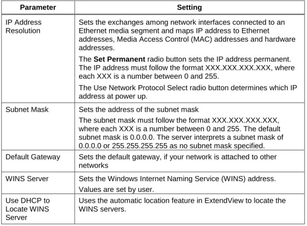
Table 4 TCP/IP Settings Parameter Setting
IP Address Resolution
Sets the exchanges among network interfaces connected to an Ethernet media segment and maps IP address to Ethernet
addresses, Media Access Control (MAC) addresses and hardware addresses.
The Set Permanent radio button sets the IP address permanent. The IP address must follow the format XXX.XXX.XXX.XXX, where each XXX is a number between 0 and 255.
The Use Network Protocol Select radio button determines which IP address at power up.
Subnet Mask Sets the address of the subnet mask
The subnet mask must follow the format XXX.XXX.XXX.XXX, where each XXX is a number between 0 and 255. The default subnet mask is 0.0.0.0. The server interprets a subnet mask of 0.0.0.0 or 255.255.255.255 as no subnet mask specified. Default Gateway Sets the default gateway, if your network is attached to other
networks
WINS Server Sets the Windows Internet Naming Service (WINS) address. Values are set by user.
Use DHCP to Locate WINS Server
Uses the automatic location feature in ExtendView to locate the WINS servers.
3. To change the Telnet/HTTP password, click Telnet/HTTP Password. The Change Password window displays.
Figure 3 Change Password Window
Type the new password in the New Password field, then in the Verify Password field. Click OK to change the password or click Cancel to exit.
Advanced Configuration Silex Page 29
Figure 4 Advanced TCP/IP Configuration Window
5. Configure the settings, as defined in Table 5.
Table 5 TCP/IP Configuration Settings Parameter Setting
TCP Connection Timeout
Sets the timeout and reset values for the TCP connections Unsolicited ARP Blocks or broadcasts unsolicited ARP
DNS Sets the DNS addresses
6. To accept changes, click OK. To cancel, click Cancel. For additional help, click Help.
NOTE: You can configure the same settings using the Web Page configuration. Simply log in using the Serial Device Server IP address and select TCP/IP. For the changes to become effective, click the
Submit button, then reset the Serial Device Server.
Configuring SNMP
The Serial Device Server Serial Device Server contains a Simple Network Management Protocol (SNMP) agent that collects and stores management information for network managers using standard SNMP commands. The management information is referenced as a hierarchically organized database called a Management Information Base (MIB).
To prevent naming conflicts, all of the manageable features of all products from all vendors are arranged in a single tree structure. Each vendor of SNMP equipment has an exclusive section of the MIB Tree. Each branch of the MIB Tree has a number and name. The path from the top of the tree down to the point of interest forms the name of that point. A name created in this way is known as an Object ID or OID.
Table 6 describes the messages used to communicate between the network manager and the SNMP agent, as defined in RFC 1157. Each SNMP message must contain a Community Name, which is used like a password. The default Community name for the Serial Device Server Serial Device Server is PUBLIC.
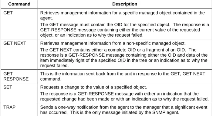
Table 6 SNMP Commands Command Description
GET Retrieves management information for a specific managed object contained in the agent.
The GET message must contain the OID for the specified object. The response is a GET-RESPONSE message containing either the current value of the requested object, or an indication as to why the request failed.
GET NEXT Retrieves management information from a non-specific managed object. The GET NEXT contains either a complete OID or a fragment of an OID. The response is a GET-RESPONSE message containing either the OID and data of the item immediately right of the specified OID in the tree or an indication as to why the request failed.
GET
RESPONSE
This is the information sent back from the unit in response to the GET, GET NEXT command.
SET Requests a change to the value of a specified object.
The response is a GET-RESPONSE message with either an indication that the requested change had been made or with an indication as to why the request failed. TRAP Sends a one-way notification from the agent to the manager that a significant event
has occurred. This is the only message initiated by the SNMP agent.
To configure the SNMP server settings:
7. Log into the Serial Device Server internal web pages using a standard web browser. Click Server Settings to access the screen shown in Figure 10. You can then enter the relevant SNMP information for your network.
Advanced Configuration Silex Page 31
Figure 5 SNMP Configuration
8. Click the Submit button to save the changes. You must then restart the Serial Device Server to make the changes take effect.
Configuring Serial Port Monitor Alert and Trap Configuration
The Serial Device Server can be configured to scan and compare the data received on the serial port to user-defined strings. A match with a string can be a source for SNMP traps and/or email alerts.
The match strings and corresponding email or web page message strings are configured from the Internal Configuration Console interface (accessible via TELNET).
Table 7 describes the Monitor Alert and Trap Configuration Commands.
Table 7 Port Monitor Alert Commands
Command Description
SHOW PORT S1 TRIGMON
Shows strings and index numbers being monitored
SET PORT S1 TRIGMON <trig #> <string>
Assigns a string to be monitored on the serial port
Example:
Local> show port s1 trigmon Index # Monitor String --- ---
Local> set port s1 trigmon 0 trigger on seeing this string Local> show port s1 trigmon
Index # Monitor String
--- ---
0: trigger on seeing this string
SHOW PORT S1 TRIGXMT Shows email or web page strings associated with TRIGMON index numbers
SET PORT S1 TRIGXMT <index #> <string> Index # = 0 to 7
Assigns email or web page string to specified TRIGMON index number
Local> show port s1 trigxmt Index # Xmit String
--- ---
0: xmit string 0 <<< default msg string
Local> set port s1 trigxmt 0 The trigger string was seen! Local> show port s1 trigxmt
Index # Xmit String --- ---
0: The trigger string was seen!
Setting up Email Alerts and SNMP Traps
After you have created the Serial Port alerts and traps, you can the use the Serial Device Server internal web pages to set up the recipient Email addresses and/or computer systems. After you have logged into the internal web pages, click Alerts and Traps on the left side of the screen and select either Email Alerts or SNMP IP Traps. (note that the Alerts and Traps menu item will not appear unless you have previously configured match strings using the Internal Configuration Console as described in the previous section). The Email Alert Configuration screen is shown below.
This screen allows you to define up to eight Email addresses that can receive alert information. Each address can receive any combination of the alerts that you have defined previously. You must enter the IP address of your SMTP server and the Email address(es) where you want the alerts to go. For example, in the above screen, the user has configured two serial port match strings. He has decided to send an alert to the mail address [email protected] if the first match string is seen on the serial port. If desired, he could create up to seven more Email addresses that could each receive any combination of these alerts.
The SNMP Trap Configuration page works exactly the same way as the Email Alert Configuration page, except that you enter the Trap Community plus the IP address and port of the destination computer(s) instead of the Email information. Up to eight separate IP addresses can be configured with any
combination of the alerts that you have defined. Note that you may also use the console command SET IP TRAP n TRIGGER console command (see appendix B) to set up the traps.
When you have finished configuring the alerts, be sure to click the Submit button to save the settings. You will also need to restart the Serial Device Server in order for the changes to take effect.
Advanced Configuration Silex Page 33
Using AT Modem Commands
The Serial Device Server firmware has an optional data filter for configuring using AT style modem commands with the serial port. This feature allows devices with an existing AT command interface to configure the unit, if the AT commands can be properly modified. You must be familiar with the general operation of AT commands. Note that AT command processing is not enabled by default. Use the command SET PORT S1 FILTER AT to enable this feature.
All commands begin with AT and are terminated by a new line unless noted below. While standard AT commands are defined to be 40 characters or less (not including the AT), the server accepts commands of up to 80 characters.
Standard AT Commands Supported
The Serial Device Server recognizes a subset of the standard AT command set. The data channel must be in the command mode for commands to be recognized. The data channel will be in command mode upon power up or reset.
There are two operating modes for the unit when the AT command option is enabled. In command mode, data received from the serial port is passed to the AT command processor, and responses are returned to the serial port. No data is sent to any network application, and any data received from the network is ignored. In data mode, data from the serial port passes to the network application, and vice versa. This is equivalent to the normal serial port operating mode without the AT command option.
Table 8 describes the AT Commands. Table 9 details the Extended AT Commands that allow the configuration of the network server operating parameters. Any AT command received, except the listed commands, are acknowledged with OK status. This allows existing modem applications to transmit commands without causing an error. These include AT<X>n, but not currently AT&<X>n, AT%<X>n, AT\<X>n, where <X> is a letter.
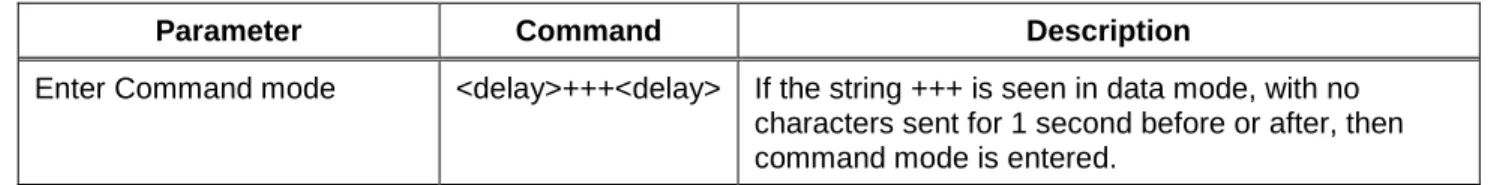
Table 8 AT Commands
Parameter Command Description
Enter Command mode <delay>+++<delay> If the string +++ is seen in data mode, with no characters sent for 1 second before or after, then command mode is entered.
Parameter Command Description
Initiate Connection Command
ATD <destination> Standard modem dialing command, redefined to initiate an internet connection to a remote computer. Indicates the IP address of the target, and optionally the TCP port number to use for connection. The T or P option (ATDT or ATDP) can be present and has no effect. If present, the IP address must be exactly 12 decimal digits with 3 for each byte of the address.
If no IP address is given, then the ECable destination address defined for the port is used.
If the destination TCP port is defined, it is separated from the IP address by a '#' character, and is 1 to 5 decimal digits.
If TCP port is defined, the ECable destination port defined for the serial port is used. If the destination port is 0, the standard Telnet port (23) is used. If the destination string ends with a semicolon, the server remains in the command mode, not the data mode, once a connection is made.
In command mode data is not passed from the remote computer, so data could be lost if the unit stays in command mode.
If the connection cannot be attempted, NO CARRIER status is returned. If the connection attempt fails, NO ANSWER status is returned.
If the connection succeeds, CONNECT status is returned.
Echo control ATEn If n=0, commands are not echoed.
If n=1, subsequent commands will be echoed. The default, upon unit reset, is for no echo (ATE0). Disconnect ATHn If n=0, any connection to a remote host is dropped.
Other value of n is ignored.
Return to data mode ATOn Exits command mode and places the serial port in the data mode.
All subsequent data is sent to the network application, if connected, until an enter command mode sequence is received. Any value of n is ignored, if present.
Quiet mode ATQn If n = 1, no result codes are returned.
If n = 0, result codes are returned to the local device. 0 is the reset default value.
Verbose mode ATVn If n = 0 and not in quiet mode, result codes are returned in numerical form.
If n = 1, results are returned as text. 1 is the reset default value.
Advanced Configuration Silex Page 35
Table 9 Extended AT Commands
Parameter Command Description
Console pass through AT#C<string> Passes the string to the server configuration console. The string can be any valid console command. Refer to your server documentation for console commands available on your unit.
Since this command does not follow the normal AT command format of <command><number>, it must be the last command on the line unless the next command is a '#' command. All characters up to the end of line or a '# will be considered part of the console command.
If console quiet mode is not is enabled, then the response will be the standard console task response. Example:
AT#Cset nw ssid silex#Csave Console Quiet mode AT#Qn If n = 0, a response to a #C command is given.
If n = 1, the response is not provided. The default after reset is 1.
Response Codes
Table 10 details the response codes for codes other than #C commands.
Table 10 Response Codes Numeric Code Description
0 OK
2 No Carrier
4 Error
5 Connect
8 No Answer
Using ExtendView for Bulk Configuration
The ExtendView Utility has a powerful bulk configuration capability that allows you download configuration information to multiple Serial Device Servers simultaneously. This can save you a significant amount of time compared to configuring each Serial Device Server individually. To use this capability:
1. From the ExtendView menu bar, select View and then Multi-Select Mode.
2. The display will change slightly so that there is checkbox by each of the Serial Device Servers listed on the main screen. Click the boxes next to each of the Serial Device Servers that you wish to configure.
3. From the ExtendView menu bar, select Server and then Multiple Configuration. The Configure Multiple Devices window will appear. This Window lets you set parameters such as subnet mask, router address, basic wireless security, and much more. When you have set all of the desired parameters, click OK and the parameters will be downloaded into the selected Serial Device Servers.
Troubleshooting Silex Page 37
Chapter 6
Troubleshooting
If you have experience problems with the Serial Device Server, please check the following troubleshooting steps:
1. Make sure that you are getting power to the Serial Device Server. The orange LED should be on solid if the proper power is being received. If it is not on, check the power supply connections, and if possible, try a different Silex Serial Device Server power supply.
2. Make sure that you have a valid network connection.
a. Make sure that your network is operating properly (that is, other devices should be able to communicate using the same hub, switch, or access poi