Tangible Teleconferencing
Jeorg Hauber1, Mark Billinghurst1, Holger Regenbrecht2 1Human Interface Technology Lab (New Zealand), University of Canterbury,Private Bag 4800, Christchurch, New Zealand
{jeorg.hauber/mark.billinghurst}@hitlabnz.org 2
DaimlerChrysler AG, P.O.Box 2360, 89013 Ulm, Germany
Abstract. This paper describes a teleconferencing application that uses real objects to interact with virtual on-screen content. A variety of tangible interaction techniques can be used to load, translate, rotate and scale shared virtual models. In addition, snapshots of real documents can be easily introduced into the system and enlarged using a tangible lens. We describe the teleconferencing interface and present results from a pilot user study.
1 Introduction
The ultimate goal of teleconferencing systems is to enable remote people to work together as easily as if they are face to face. Unfortunately this is still far from being achieved. For example, with an audio only interface such as ThunderWire [7], participants are unable to exchange non-verbal cues, while with desktop video conferencing there is often a lack of spatial cues [14]. Even in high end immersive virtual environments such as GreenSpace [10] remote users are represented as virtual avatars that cannot display all the nuances of face to face communication.
In a face to face meeting real objects and interactions with the real world play an important role [6]. However, with current technology it is difficult to bring elements of the real world into a remote communication space. In most video conferencing applications users cannot share real documents, or manipulate tangible objects.
In this paper we describe a virtual conferencing space that uses tangible interaction techniques [8] to bridge between the real and virtual spaces. Our goal is to bring real documents and objects into screen-based collaborative environments.
2 Related Work
Over the past decade teleconferencing options have increased. People can now use cell phones, on-line chat services or free video conferencing suites such as Microsoft’s NetMeeting. More sophisticated users may have access to desktop virtual conferencing spaces in which they can navigate through an on-screen virtual space.
Computer supported collaborative work (CSCW) systems vary widely in the functions they provide. Some applications such as IBM Lotus Notes or Microsoft Outlook utilize the desktop metaphor from today's graphical user interfaces and bring them into a distributed, collaborative context. The main shortcoming of these systems is their lack of synchronous, distributed communication. Often, simultaneous telephone conferencing is needed to substitute for this lack of synchronicity.
Recent video conferencing systems overcome this limitation by partially integrating CSCW content (e.g. chat and whiteboard) with synchronous video and audio. In most cases, application or 2D data sharing is offered as an option. These systems are typically used in special rooms or facilities in large companies. Although able to share audio and video data, there is often limited ability to interact with three dimensional virtual content or share spatial cues.
Collaborative virtual environments do connect distributed users in a three-dimensional shared graphical environment [2, 5]. These environments can be highly realistic and vivid, but are mostly synthetic or abstract and cannot really be a substitute for real world communication. For example, the representations of the users are either symbolic or as virtual avatars (dynamic 3D geometry). Neither are able to convey the non-verbal nuances of real face to face conversation.
In projects such as the "Office of the future" work [12] remote participants and places are integrated into one shared environment. A similar approach to integrating participants in a spatial simulation of reality is project VIRTUE [9]. Here, a combination of advanced computer vision and computer graphics methods are used to provide a comprehensive system for video conferencing. With this system the impression is created that three remote participants actually sit around the same table.
Although developments have been made in collaborative interfaces that share natural audio and visual cues between remote users, there has been less work on incorporating real objects into the interface. Projects such as Psybench [4] and inTouch [3] allow remote users to move real objects together. In these cases the focus is on remote control of physical objects, rather than using physical objects to control virtual information.
Unlike this previous work, our research combines elements of tangible user interface design with a desktop virtual environment conferencing interface. In this way we can seamlessly link real and virtual worlds in a collaborative setting. In the next section we describe the cAR/PE! interface that our work is based on, and then we present our tangible conferencing interface.
3 The cAR/PE! Conferencing Space
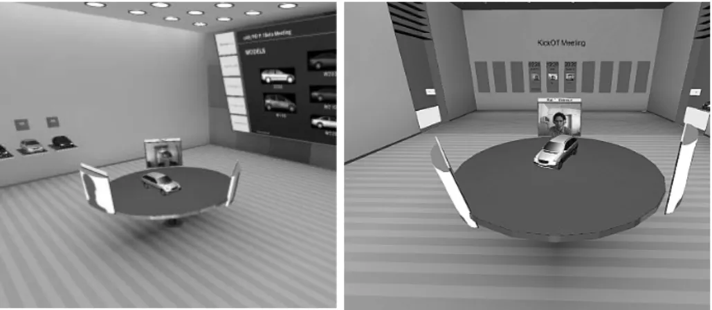
Our work is an enhancement of the cAR/PE! desktop collaborative virtual environment [13]. This is software that runs on a desktop computer with a web camera attached, showing a three dimensional virtual conference room environment (see figure 1). Remote users are shown as virtual avatars in the conferencing space with live video texturing onto their virtual representations.
Fig. 1. The cAR/PE! interface
The cAR/PE! interface allows multiple remote participants to communicate over a network in an environment simulating a traditional face-to-face meeting. Integrated into the virtual environment are live video streams of the participants spatially arranged around a virtual table, a large virtual presentation screen for 2D display, and shared 3D virtual models (figure 2). In the center of the room there is table on which alternative 3D virtual models can be placed. Each participant can change his/her view into the virtual environment using a SpaceMouse input device. User movements are transmitted to the other participants and used to control the orientation of the virtual video avatars. Thus each user can see where the other participants are looking.
Fig. 2. The cAR/PE! virtual environment
The cAR/PE! application is written in C++ and uses the OpenInventor graphics library [11] for its 3D graphics components and interaction. It runs on the Microsoft Windows operating system. Although designed for low-end hardware, cAR/PE! represents the state-of-the art in desktop collaborative virtual environments.
3 Tangible Teleconferencing
Although the cAR/PE! conferencing space supports intuitive spatial conferencing it still creates an artificial separation between the real and virtual worlds. Our research goal was to extend this conferencing application to support the following:
• The use of real objects to load three-dimensional virtual content • The use of real objects to manipulate virtual content
• Allowing users to bring real documents into the shared conferencing space
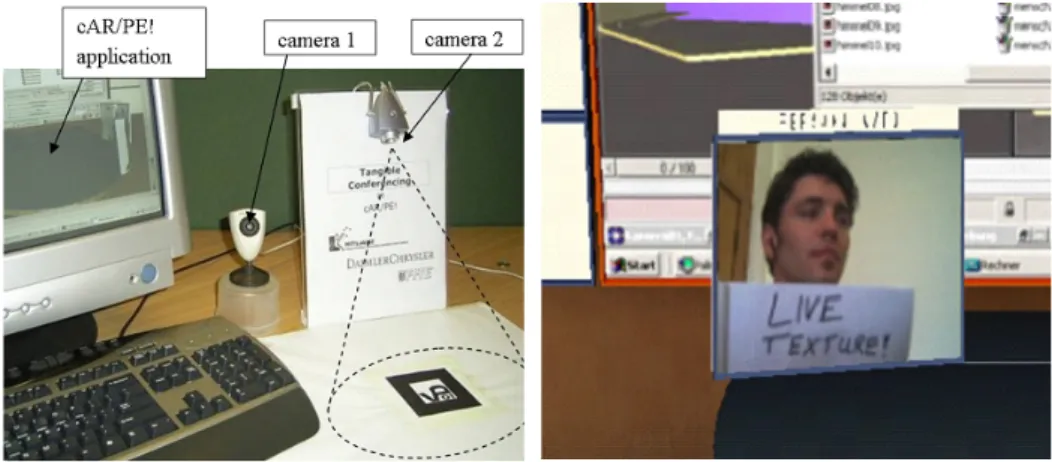
Figure 3 shows the hardware setup. Two web-cams are connected to a desktop PC running the conferencing application. Camera 1 is used for capturing the user’s face. Its images are mapped onto a virtual avatar’s using live video texturing (Figure 4). Permanently updating the avatar video texture is a very resource consuming task, so the camera resolution is just 160 x 120 pixels. The second camera (Camera 2) is used for detecting tangible interaction objects. It is placed 24 cm above the table and points down at a marker on the table. When objects are moved in front of this marker they are detected by the camera. The camera is used to take high quality snapshots so its resolution is set to 800 x 600 pixels.
Fig. 3: Tangible conferencing hardware setup Fig. 4: Avatar with live video texture
3.1 Model Loading
In our collaborative interface we first needed an intuitive way to load virtual models into the conferencing space. This is accomplished through the use of small square cardboard model markers Each of these markers is associated with a different virtual model. When a marker is placed under the desktop camera (camera 2), the ARToolKit tracking library [2] is used to recognize the pattern on the marker and load the appropriate 3D model into the conferencing space. When different model markers are in view of the camera the individual virtual models associated with them are loaded onto the table in the virtual conferencing space. Thus the markers allow users to easily load a variety of different virtual models.
3.2 Model Manipulation
Once models have been loaded into the conferencing space they can be manipulated using a different set of tangible interface objects. In our work we have explored two different approaches to model manipulation:
• Mouse based: Tangible markers are used to attach virtual manipulators to the model which the user can then interact with using mouse input. • Tool-based: Physical tools are used to select the manipulation mode and
also perform the virtual object manipulation.
3.2.1 Mouse-based Manipulation
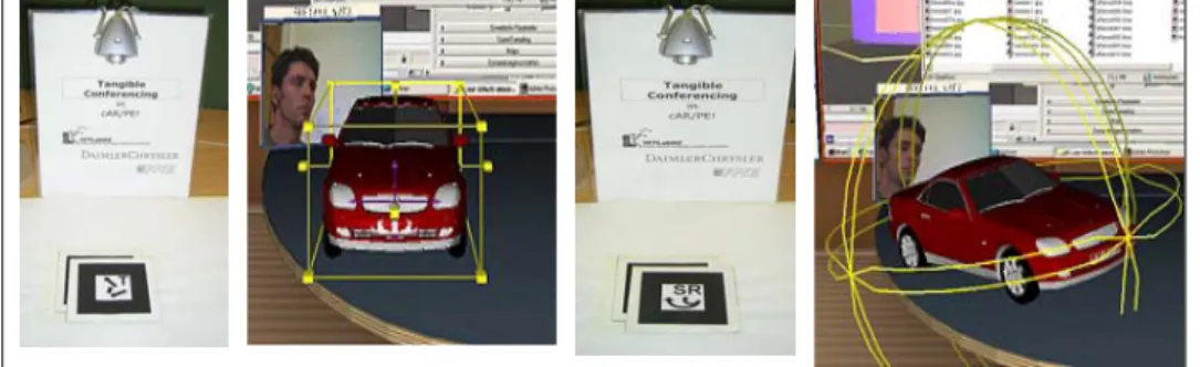
We enable users to rotate, translate, and scale the virtual models by using three manipulation markers. When these markers are placed on top of a model marker, an Open-Inventor manipulator widget appears on the virtual model. This allows a user to perform mouse- and keyboard-operated manipulations to the virtual model.
Placing a translation marker over the model marker representing a red car causes a virtual translation widget to appear over the car model. Selecting the widget with the mouse allows a user to freely translate the model (figure 5a). Similarly, placing a rotation/scaling marker over the car model marker causes the rotation/scaling widget to appear (figure 5b). When different model markers are in view different virtual manipulators appear on the models on the table in the virtual space
Fig. 5a: Model translation Fig. 5b: Model rotation
3.2.2 Tool-based Manipulation
As an alternative to using marker and mouse/keyboard input we also explored the use of physical tools that could be used for model translation, rotation and scaling.
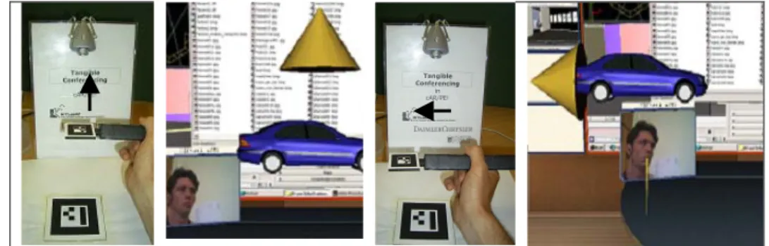
Translation: The translation tool can be used to move a model along all three axes in space. The tool consists of a ARToolKit marker attached to a handle. When this is held under the desktop camera the motion of the tool is mapped onto the virtual model (Figure 6). A distance vector is calculated between the current tool position
and its initial position. This vector is used to update the positon of the virtual model. Thus the translation tool is a relative input device. For example, when the marker is moved upwards after being detected, the virtual object will start moving upwards as well. The translation speed itself depends on the distance to the initial position; a large offset causes a fast translation while a small offset produces slow motion. Six virtual arrow cones are shown around the model to give visual feedback about the direction and amount of the actual translation speed. The diameter of every cone is used as an indicator for the amount of translation speed component.
Fig. 6: Tool-based model translation
Rotation: The Rotation tool (figure 7) can be used to rotate a model about its x- y- or z-axis in space. The tool consists of three markers that are arranged in a triangular shape. Each marker represents one of the three rotation axes. Once one of the markers is held under the dekstop camera, rotation about the corresponding axis begins. The speed and direction can be controlled by the distance of the tool to the camera. For example, if the rotation tool is close to the camera with the z-axis marker facing the camera, the virtual model will start rotating clockwise about the z-axis. As the tool is moved away the rotation speed decreases until it finally reverses its direction.
Fig. 7: The rotation tool Fig. 8: The scaling tool
Scaling: Model scaling is achieved by using a physical tool shaped like a magnifying glass and placing it under the desktop camera (figure 8). The scale tool’s initial
position is detected and stored and as the user moves the tool, the relative distance to the camera is calculated and used to determine a scale-factor that is applied to the virtual model. The closer the scale tool is to the camera, the more the model is scaled.
3.3 Incorporating Real Documents
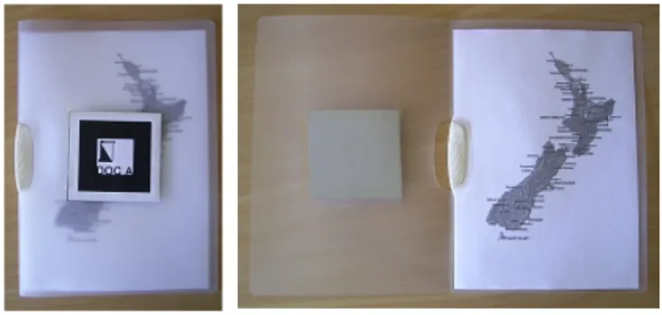
The final functionality we wanted to add to the interface was the ability to bring real documents into the virtual environment. The document we want to capture is placed inside a folder with a marker on the cover (figure 9). If the closed folder is brought into the tangible interaction space, the marker is detected and a virtual model of the document pops up on the table. In this way a virtual representation of the real document can easily be loaded into the cAR\PE! environment.
Fig. 9: The Document folder
Photo Texture: After the document model is loaded into the scene the user is able to take a snapshot of the real document and display this as a texture map on the surface of the virtual document model. When the real folder is opened the cover marker is no longer visible and our software knows to take a picture of the document and texture map it onto the virtual model (figure 10). This allows the user to share text or pictures from any real document with another person in the cAR/PE! environment.
Shared Snapshot: If the user wants to share a document he or she can show a large snapshot on the virtual projection screen where it is visible to everyone. To do this he or she has to move the virtual document model close to the projection wall and open the real folder. The photo snapshot now appears on the projection wall.
Our software also allows the user to immediately add physical annotations to the shared document view with conventional pens . To update the shared snapshot all the user has to do is close and reopen the document folder. So the user can write on the document and have those annotations appear in the cAR\PE! environment (figure 11).
Fig. 11: Adding Annotations
Texture Zooming: For some tasks the user may want to zoom into part of a
document to share a closer view. The user can magnify and move the image texture with the scale tool. Holding the scale tool over the real document enlarges the virtual image texture shown on the projection wall. The closer the scale tools is to the camera, the bigger the texture’s updated zoom factor. By moving the tool the user can also pan around the texture. Thus with these two techniques it is easy for the user to pan and zoom into any part of the document image.
4. User Feedback
In order to test the usability of our interface we conducted a simple pilot usability study with nine subjects. At the beginning of each test, every participant was given a 30 minute introduction on how the different markers and tools were supposed to be used. During this introduction, every participant was allowed to try the markers/tools and make himself or herself familiar with the different forms of actions they affected. After this introduction, two simple tasks were completed with the interface.
Task1: Object Manipulation: A car model had to be loaded into the scene and then manipulated so that it would fit into a semi-transparent box which was placed on a podium next to the virtual table. Once the car’s orientation, position and size was within a tolerable range the appearance of the box turned from red to green and the task was completed. In order to perform the manipulation, the participants chose between the mouse- based manipulation technique or the fully tangible tools.
Task 2: Document Annotation: In the second task the participants were asked to reconstruct a snapshot that showed a finished Tic Tac Toe game. A shared snapshot had to be created from a real document with an incomplete Tic Tac Toe board, physical annotations had to be added and the image had to be magnified.
After the tasks were completed, we asked the participants how easy it was to learn how to use the various interface elements, and how well they felt they could use the interface. They filled out a simple survey where they were asked to rate ease of learning and ease of interaction for each tool on a scale of 1 to 7 (1 was ‘not very easy’ and 7 was ‘very easy’). They were also timed how long to complete each task.
4.1 Results
In general subjects found the interface easy to use and were able to complete the tasks relatively quickly. The time for the completion of the manipulation task averaged 5 minutes, while the document task ould be completed in 3 minutes.
The Translation- tool and the Scaling-tool were rated as very easy to learn by most of the participants, with average scores of 6.2 and 6.3 respectively. The translation tool was also thought to be relatively easy to use, with an average grade of 5.1. The subjects especially liked the high sensitivity of the tool and the visual feedback showing the actual motion in space.
However the Rotation-tool was found to be not as easy to learn, receiving an average score of 5.7. It was also graded as less usable with an average score of only 4.4. Many subjects commented that this was because of the unnatural mapping of a translation movement to a rotation. It was difficult to mentally map up and down motion of the tool to clockwise and counter-clockwise rotation of the virtual model. Users almost always tried to rotate the virtual model by initially turning the model marker itself, suggesting an interesting direction for further interaction analysis.
In terms of document interaction, most of the subjects liked the folder metaphor and could immediately understand how to update snapshots and add annotations. Adding annotations was given average score of 6.1 on the ease of use scale.
Eight of the nine subjects thought that the use of physical objects as controls was helpful. Furthermore, when they had to decide between using mouse-based or tool-based operations for model manipulation, six out of nine participants preferred the fully tangible tools. This may have been due to the difficulty of mouse selection of the virtual manipulators. For example, the translation-tool allowed simultaneous movement along all three axes in space. In contrast, the mouse-based translation-tool “handlebox”, only allows the models to be translated along a single axis.
5. Conclusions
The main theme of our work is to seamlessly blend elements of the real world with shared digital content in a desktop collaborative virtual environment. With the tools that we have developed people can use real objects to place virtual models into the cAR/PE! environment and to translate, rotate and scale these models. In addition we
have developed document interaction tools that enable users to bring real documents into the virtual environment, and annotate the documents using pen and pencil. In this way we hope to make CSCW systems easier to use and to reach more potential users.
We also completed an initial pilot study that highlighted some of the advantages and disadvantages of our system. Users felt that the system was easy to learn because of use of real object interaction, and preferred tangible tools were over combined maker and mouse interaction. However they found the rotation tool difficult to use and also sometimes had trouble with failure with the computer vision marker detection.
This feedback has given us some good directions for future work. We next plan on completing a more rigorous user study and building further intuitive tangible interaction methods based on the results from this study.
6 References
1. ARToolKit website: http://www.hitl.washington.edu/artoolkit/
2. Benford, S. D., Brown, C. C., Reynard, G. T. and Greenhalgh, C. M (1996): "Shared Spaces: Transportation, Artificiality and Spatiality", In Proceedings of CSCW ‘96, Nov. 16th -20th, 1996, New York, NY: ACM Press.
3. Brave, S., and Dahley, D. inTouch: a medium for haptic interpersonal communication. Extended Abstracts of CHI’97 (Atlanta GA, Mach 1997). ACM Press, 363-364.
4. Brave, S., Ishii, H. and Dahley, A., Tangible Interfaces for Remote Collaboration and Communication , in Proceedings of CSCW '98, (Seattle, Washington USA, November 1998), ACM Press, pp. 169-178.
5. Frecon, E., Smith, G., Steed, A., Stenius, M., Stahl, O. (2001) An Overview of the COVEN Platform, Presence: Teleoperators and Virtual Environments, 10(1), February 2001, pp. 109-127 , MIT Press
6. Garfinkel, H. (1967) Studies in Ethnomethodology. Englewood Cliffs, NJ: Prentice-Hall. 7. Hindus, D., Ackerman, M., Mainwaring, S., Starr, B. Thunderwire: A Field study of an
Audio-Only Media Space. In Proceedings of CSCW ‘96, Nov. 16th -20th, 1996, New York, NY: ACM Press.
8. Ishii, H., Ullmer, B. Tangible Bits: Towards Seamless Interfaces between People, Bits and Atoms. In proceedings of CHI 97, Atlanta, Georgia, USA, ACM Press, 1997, pp. 234-241. 9. Kauff, P. & Schreer, O. (2002). An Immersive 3D Video-Conferencing System Using
Shared Virtual Team User Environments. ACM Collaborative Environments, CVE 2002, Bonn, Germany, Sept./Oct. 2002.
10. Mandeville, J., Davidson, J., Campbell, D., Dahl, A., Schwartz, P., and Furness, T. A Shared Virtual Environment for Architectural Design Review. In CVE ‘96 Workshop Proceedings, 19-20th September 1996, Nottingham, Great Britain.
11. OpenInventor website: http://oss.sgi.com/projects/inventor/
12. Raskar R., Welch, G., Cutts, M., Lake, A., Stesin, L., and Fuchs, H. (1998). The Office of the Future : A Unified Approach to Image-Based Modeling and Spatially Immersive Displays. "ACM SIGGRAPH 1998, Orlando FL
13. Regenbrecht, Ott, C., Wagner, M., H., Lum, T., Kohler, P., Wilke, W., Mueller, E. (2003). An Augmented Virtuality Approach to 3D Videoconferencing. International Symposium on Mixed and Augmented Reality, Tokyo/Japan, October 2003.
14. Sellen, A., Buxton, B. Using Spatial Cues to Improve Videoconferencing. In Proceedings CHI ‘92, May 3-7, 1992, ACM: New York , pp. 651-652.