Cinterion
®
BGS5
AT Command Set
Version:
01.100
DocId:
BGS5_ATC_V01.100
GENERAL NOTE
THE USE OF THE PRODUCT INCLUDING THE SOFTWARE AND DOCUMENTATION (THE "PRODUCT") IS SUBJECT TO THE RELEASE NOTE PROVIDED TOGETHER WITH PRODUCT. IN ANY EVENT THE PROVI-SIONS OF THE RELEASE NOTE SHALL PREVAIL. THIS DOCUMENT CONTAINS INFORMATION ON GEMALTO M2M PRODUCTS. THE SPECIFICATIONS IN THIS DOCUMENT ARE SUBJECT TO CHANGE AT DISCRETION OF GEMALTO M2M. GEMALTO M2M GMBH GRANTS A NON-EXCLUSIVE RIGHT TO USE THE PRODUCT. THE RECIPIENT SHALL NOT TRANSFER, COPY, MODIFY, TRANSLATE, REVERSE ENGI-NEER, CREATE DERIVATIVE WORKS; DISASSEMBLE OR DECOMPILE THE PRODUCT OR OTHERWISE USE THE PRODUCT EXCEPT AS SPECIFICALLY AUTHORIZED. THE PRODUCT AND THIS DOCUMENT ARE PROVIDED ON AN "AS IS" BASIS ONLY AND MAY CONTAIN DEFICIENCIES OR INADEQUACIES. TO THE MAXIMUM EXTENT PERMITTED BY APPLICABLE LAW, GEMALTO M2M GMBH DISCLAIMS ALL WAR-RANTIES AND LIABILITIES. THE RECIPIENT UNDERTAKES FOR AN UNLIMITED PERIOD OF TIME TO OBSERVE SECRECY REGARDING ANY INFORMATION AND DATA PROVIDED TO HIM IN THE CONTEXT OF THE DELIVERY OF THE PRODUCT. THIS GENERAL NOTE SHALL BE GOVERNED AND CONSTRUED ACCORDING TO GERMAN LAW.
Copyright
Transmittal, reproduction, dissemination and/or editing of this document as well as utilization of its contents and communication thereof to others without express authorization are prohibited. Offenders will be held liable for payment of damages. All rights created by patent grant or registration of a utility model or design patent are reserved.
Copyright © 2013, Gemalto M2M GmbH, Gemalto Company
Trademark Notice
Gemalto, the Gemalto logo, are trademarks and service marks of Gemalto and are registered in certain coun-tries.
Microsoft and Windows are either registered trademarks or trademarks of Microsoft Corporation in the United States and/or other countries. All other registered trademarks or trademarks mentioned in this document are property of their respective owners.
Document Name:
Cinterion
®
BGS5 AT Command Set
Version:
01.100
Date:
November 25, 2013
DocId:
BGS5_ATC_V01.100
1. Introduction... 12
1.1 Scope of the document ... 12
1.2 Related documents ... 13
1.3 Glossary of Terms ... 15
1.4 Document Conventions ... 16
1.4.1 Quick Reference Table ... 16
1.4.2 Superscript notation for parameters and values ... 17
1.5 AT Command Syntax ... 18
1.5.1 Using Parameters ... 18
1.5.2 Concatenating AT Commands... 19
1.5.3 Application Design Considerations ... 19
1.6 Communication between Customer Application and BGS5 ... 20
1.7 Supported character sets ... 21
1.7.1 GSM alphabet tables and UCS2 character values ... 23
1.7.2 UCS2 and GSM character coding and conversion ... 25
1.7.2.1 Output of SIM data (ME to TE) ... 25
1.7.2.2 Input of SIM data (TE to ME) ... 26
1.8 Unsolicited Result Code Presentation... 27
1.8.1 Common URCs... 27
1.9 Errors and Messages ... 29
2. Configuration Commands... 30
2.1 AT&F Reset AT Command Settings to Factory Default Values ... 30
2.2 AT&V Display current configuration ... 31
2.2.1 AT&V responses... 32
2.3 AT&W Store AT Command Settings to User Defined Profile ... 33
2.4 ATQ Result Code Presentation Mode ... 34
2.5 ATV Result code format mode ... 35
2.5.1 Verbose and numeric result codes ... 35
2.6 ATX CONNECT Result Code Format ... 36
2.7 ATZ Restore AT Command Settings from User Defined Profile ... 37
2.8 AT+CFUN Functionality Level... 38
2.9 AT^SMSO Switch Off BGS5 ... 40
2.10 AT+CMEE Error Message Format ... 41
2.10.1 CME/CMS Error Code Overview ... 42
2.11 AT+CSCS Character Set ... 50
2.12 AT^SCFG Extended Configuration Settings ... 51
2.13 AT^SPOW Set UART Mode and SLEEP Mode on UART ... 69
3. Status Control Commands ... 71
3.1 AT+CEER Extended Error Report... 71
3.1.1 Release causes for L3 Call Control (CC)... 72
3.1.2 Internal failure causes... 74
3.1.3 Release causes for packet switched features ... 76
3.1.4 SS network reject causes ... 77
3.1.5 SS network error causes ... 78
Contents
Contents
3.2 AT^SIND Extended Indicator Control... 79
3.3 AT+CPAS Activity Status ... 86
4. Serial Interface Control Commands... 87
4.1 AT\Q Flow Control... 87
4.2 AT&C Set Data Carrier Detect (DCD) Line Mode ... 88
4.3 AT&D Set Data Terminal Ready (DTR) Line Mode... 89
4.4 AT&S Set Data Set Ready (DSR) Line Mode ... 90
4.5 ATE AT Command Echo ... 91
4.6 AT+IPR Bit Rate... 92
4.6.1 Autobauding... 93
4.7 AT+CMUX Multiplex mode... 94
5. Identification Commands... 96
5.1 ATI Display product identification information ... 96
5.2 AT+CGMI Request manufacturer identification... 97
5.3 AT+CGMM Request model identification ... 98
5.4 AT+CGMR Request revision identification of software status... 99
5.5 AT+CGSN Request International Mobile Equipment Identity (IMEI)... 100
5.6 AT+GSN Request International Mobile Equipment Identity (IMEI) ... 100
5.7 AT+CIMI Request International Mobile Subscriber Identity (IMSI)... 101
6. Security Commands ... 102
6.1 AT+CPIN PIN Authentication ... 102
6.2 AT+CPIN2 PIN2 Authentication ... 104
6.3 AT+CLCK Facility lock ... 106
6.4 AT+CPWD Change Password ... 110
7. Call related Commands... 113
7.1 ATA Connect to Incoming Call ... 113
7.2 ATD Mobile originated call to specified number ... 114
7.3 ATD><mem><n> Mobile originated call using specific memory and index number ... 116
7.4 ATD><n> Mobile originated call from active memory using index number ... 118
7.5 ATD><str> Mobile originated call from active memory using corresponding field ... 119
7.6 ATDL Redial last number used ... 120
7.7 ATH Disconnect existing connection... 121
7.8 AT+CHUP Hang up call ... 122
7.9 AT^SHUP Hang up call(s) indicating a specific 3GPP TS 24.008 release cause ... 123
7.10 ATS0 Set number of rings before automatically answering a call ... 124
7.11 ATO Switch from command mode to data mode / PPP online mode... 125
7.12 +++ Switch from data mode or PPP online mode to command mode ... 126
7.13 AT+CBST Select Bearer Service Type ... 127
7.14 AT+CSTA Select type of address ... 129
7.15 AT+CRLP Configure RLP Parameters for Outgoing Non-Transparent Data Calls ... 130
7.16 AT+CLCC List of current calls... 131
7.17 AT+CR Service reporting control ... 133
7.18 AT+CRC Incoming Call Indication Format ... 134
7.19 ATS6 Set pause before blind dialing ... 136
7.20 ATS7 Set number of seconds to wait for connection completion ... 137
7.21 ATS8 Comma Dial Pause Time ... 138
8. Network Service Commands ... 140
8.1 AT+COPN Read operator names ... 140
8.2 AT+COPS Operator Selection ... 141
8.3 AT+CREG Network Registration Status... 144
8.4 AT+CSQ Signal quality ... 146
8.5 AT+CPOL Preferred Operator List ... 147
8.6 AT+CPLS Select Preferred Operator List ... 148
8.7 AT+CTZR Time Zone Reporting ... 149
8.8 AT+CTZU Automatic Time Zone Update ... 151
8.9 AT^SMONP Display Neighbor Cell Information ... 152
8.9.1 AT^SMONP (Enhanced) Responses... 152
8.10 AT^SMONI Display Server Cell Information... 154
8.10.1 AT^SMONI (Enhanced) Responses ... 154
8.10.2 Service states ... 155
8.11 AT^SNMON Network monitoring... 157
9. Supplementary Service Commands ... 159
9.1 AT+CACM Accumulated call meter (ACM) reset or query ... 159
9.2 AT+CAMM Accumulated call meter maximum (ACMmax) set or query... 160
9.3 AT+CAOC Advice of Charge Information... 161
9.4 AT+CCUG Closed User Group ... 162
9.5 AT+CCFC Call forwarding number and conditions control ... 164
9.6 AT+CCWA Call Waiting ... 167
9.7 AT+CHLD Call Hold and Multiparty... 170
9.8 AT+CLIP Calling Line Identification Presentation ... 172
9.9 AT+CLIR Calling Line Identification Restriction ... 174
9.10 AT+COLP Connected Line Identification Presentation ... 175
9.11 AT+CPUC Price per unit and currency table... 177
9.12 AT+CSSN Supplementary service notifications ... 179
9.13 AT+CUSD Unstructured Supplementary Service Data ... 181
10. Internet Service Commands ... 183
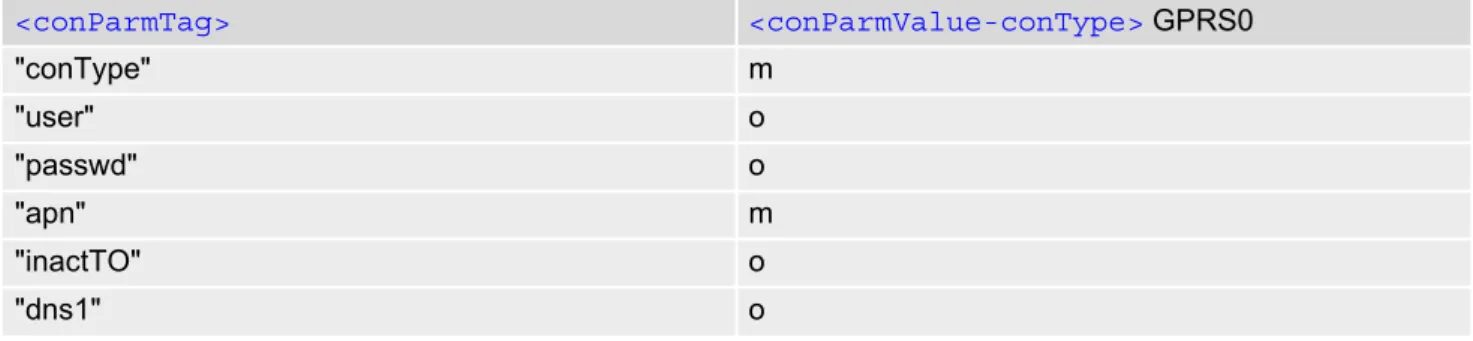
10.1 AT^SICS Internet Connection Setup Profile... 187
10.1.1 Example: GPRS connection profile ... 189
10.2 AT^SICI Internet Connection Information... 190
10.2.1 Checking Connection Profile Status ... 191
10.3 AT^SIPS Internet Profile Storage... 193
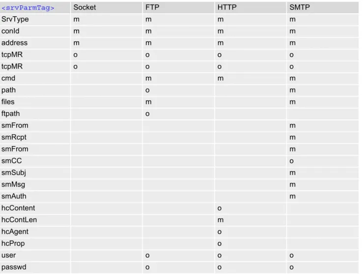
10.4 AT^SISS Internet Service Setup Profile ... 194
10.5 AT^SISI Internet Service Information ... 201
10.6 AT^SISO Internet Service Open ... 203
10.7 AT^SISC Internet Service Close ... 207
10.8 AT^SISR Internet Service Read Data ... 208
10.8.1 Example: Socket Host Reads Small Amounts of UDP Data Packets (URC Mode)... 210
10.9 AT^SISW Internet Service Write Data... 211
10.9.1 Usage of parameter <eodFlag>... 213
10.10 AT^SIST Enter Transparent Access Mode ... 214
10.11 AT^SISH Internet Listener Service Disconnect... 216
10.12 AT^SISX Internet Service Execution... 217
10.13 AT^SISE Internet Service Error Report... 219
Contents
10.14.1 Information Elements Related to the Service Application... 221
10.14.2 Information Elements Related to FTP Service... 223
10.14.3 Information Elements Related to HTTP Service ... 224
10.14.4 Information Elements Related to SMTP Service ... 224
10.15 Examples of how to Configure and Use Internet Service Profiles... 225
10.15.1 Selecting URC Mode or Polling Mode ... 225
10.15.2 Configuring Socket Listener... 225
10.15.3 Configuring Socket Client for Calling a Socket Listener on Another Host ... 226
10.15.4 Accepting / Rejecting Socket Connect Request from Remote Client ... 226
10.15.5 Autoanswering Socket Connect Request from Remote Client ... 227
10.15.6 Socket Client Sends Data via TCP Connection (Polling Mode)... 228
10.15.7 Socket Client Sends Data via TCP Connection with URCs... 229
10.15.8 UDP Scenario ... 229
10.15.9 Creating Transparent TCP Socket Client ... 231
10.15.10 Opening and Closing Transparent TCP Service... 231
10.15.11 Transparent TCP Client Receives Data While in AT Command Mode... 232
10.15.12 Server Disconnects While Transparent TCP Service is in Transparent Access Mode 233 10.15.13 Server Disconnects While Transparent TCP Service is in AT Command Mode and Data is Pending ... 234
10.15.14 FTP Download to FFS (URC Mode) ... 235
10.15.15 FTP Upload Single File (URC Mode)... 236
10.15.16 HTTP Download Using TLS... 237
10.15.17 HTTP Post ... 237
10.15.18 SMTP Sending Mail with Attachment from FFS ... 238
10.15.19 Ping... 239
11. Packet Domain Related Commands ... 241
11.1 AT+CGACT PDP context activate or deactivate ... 241
11.2 AT+CGANS Manual response to a network request for PDP context activation ... 243
11.3 AT+CGATT GPRS attach or detach ... 245
11.4 AT+CGAUTO Automatic response to a network request for PDP context activation ... 246
11.5 AT+CGDATA Enter data state ... 248
11.5.1 Automatic deactivation of PDP context during dial-up PPP... 249
11.6 AT+CGDCONT Define PDP Context ... 250
11.7 AT+CGCMOD PDP Context Modify... 252
11.8 AT+CGEREP GPRS event reporting ... 253
11.9 AT+CGPADDR Show PDP address ... 255
11.10 AT+CGQMIN Quality of Service Profile (Minimum acceptable) ... 256
11.11 AT+CGQREQ Quality of Service Profile (Requested) ... 259
11.12 AT+CGREG Packet Domain Network Registration Status ... 262
11.13 AT+CGSMS Select service for MO SMS messages ... 264
11.14 ATA Manual acceptance of a network request for PDP context activation ... 265
11.15 ATD*99# Request Packet Domain Service ... 266
11.16 AT^SGAUTH Set Type of Authentication for PDP-IP Connections... 267
11.17 AT^SGCONF Configurable GPRS Multislot Class ... 269
12. Short Message Service (SMS) Commands... 270
12.1 SMS Parameters ... 270
12.2 AT+CMGC Send SMS Command... 274
12.4 AT+CMGF Select SMS message format ... 276
12.5 AT+CMGL List SMS messages from preferred store... 277
12.6 AT+CMGR Read SMS messages... 279
12.7 AT+CMGS Send SMS... 281
12.8 AT+CMGW Write Short Messages to Memory ... 282
12.9 AT+CMMS More Messages to Send... 284
12.10 AT+CMSS Send short messages from storage ... 285
12.11 AT+CNMA New Message Acknowledgement to ME/TE... 286
12.12 AT+CNMI SMS Event Reporting Configuration ... 287
12.13 AT+CPMS Preferred SMS message storage... 290
12.14 AT+CSCA SMS Service Center Address... 292
12.15 AT+CSCB Select Cell Broadcast Message Indication ... 293
12.16 AT+CSDH Show SMS text mode parameters... 294
12.17 AT+CSMP Set SMS Text Mode Parameters ... 295
12.18 AT+CSMS Select Message Service... 297
12.19 AT^SMGL List Short Messages from preferred store without setting status to REC READ ... 299
12.20 AT^SMGR Read short message without setting status to REC READ ... 300
13. SIM related Commands ... 301
13.1 AT+CCID SIM Card Identification Number... 301
13.2 AT+CRSM Restricted SIM Access... 302
13.3 AT+CSIM Generic SIM Access ... 304
14. SIM Application Toolkit (SAT) Commands... 305
14.1 AT^SSTA Remote-SAT Interface Activation ... 305
14.2 AT+STKPRO SAT Proactive Command URCs... 308
14.3 AT+STKTR SAT Terminal Response Commands ... 314
14.4 AT+STKENV SAT Envelope Command... 319
14.5 AT+STKCC SAT Call Control Notification... 321
14.6 AT+STKCNF SAT Proactive Session Status ... 323
14.7 Examples of how to Configure and Use the SAT ... 325
15. Phonebook Commands... 327
15.1 AT+CNUM Read own numbers... 327
15.2 AT+CPBR Read from Phonebook... 328
15.3 AT+CPBS Select phonebook memory storage ... 331
15.4 AT+CPBW Write into Phonebook ... 333
15.5 AT+CPBF Find phonebook entries ... 335
15.6 AT+CSVM Set voice mail number... 337
16. Audio Commands ... 339
16.1 AT+CMUT Mute control ... 339
16.2 AT+VTD Tone duration ... 340
16.3 AT+VTS DTMF and tone generation... 341
16.4 AT^SNFI Set microphone path parameters ... 343
16.5 AT^SNFM Set microphone audio path and power supply... 344
16.6 AT^SNFO Set audio output (= loudspeaker path) parameter ... 345
16.7 AT^SNFS Select audio hardware set... 346
Contents
17. Java related Commands ... 350
17.1 AT^SJAM Manage Java Application ... 350
17.2 AT^SJDL Java Download... 353
17.3 AT^SJNET Set Dialup Network Access Parameters... 355
17.4 AT^SJOTAP Over The Air Application Provisioning ... 357
17.5 AT^SJMSEC Java Midlet Security ... 360
17.6 AT^SJRA Run Java Application ... 363
18. Miscellaneous Commands... 364
18.1 A/ Repeat Previous Command Line ... 364
18.2 ATS3 Command Line Termination ... 365
18.3 ATS4 Response Formatting ... 366
18.4 ATS5 Command Line Editing ... 367
18.5 AT^SFDL Firmware Download... 368
18.6 AT^SFSA Flash File System Access ... 369
19. Hardware related Commands ... 378
19.1 AT+CCLK Real Time Clock... 378
19.2 AT+CALA Alarm Configuration ... 379
19.3 AT^SCTM Critical Operating Temperature Monitoring... 382
19.4 AT^SLED LED Feature ... 384
19.5 AT^SRADC Configure and Read ADC Measurement... 386
19.6 AT^SSPI Serial Protocol Interface ... 389
19.6.1 Selecting SPI Mode ... 391
19.6.2 Transmitting Data over AT Interface... 392
19.6.2.1 Structure of Messages on the I²C Bus ... 393
19.6.2.2 Structure of Messages on the SPI ... 394
19.6.3 Error Handling on the I²C Bus... 394
19.6.4 Example: Using I²C Bus... 396
19.6.5 Example: Transfer and Response Messages on SPI ... 397
19.7 AT^SWDAC PWM Signal Configuration for DAC... 398
20. General Purpose I/O (GPIO) Pin related Commands... 400
20.1 AT^SCPIN Pin Configuration ... 400
20.1.1 GPIO Configuration Table ... 401
20.2 AT^SGIO Get IO state of a specified pin or port ... 403
20.3 AT^SSIO Set IO state of a specified pin or port ... 404
20.4 AT^SCPOL Polling Configuration... 405
20.5 AT^SSCNT Start and Stop Pulse Counter ... 406
20.5.1 Using the Pulse Counter in Start-Stop Counter Mode ... 407
20.6 AT^SCCNT Configure Pulse Counter ... 408
20.6.1 Using the Pulse Counter in Limit Counter Mode... 409
20.7 AT^SPIO GPIO Driver Open/Close ... 410
21. Appendix ... 411
21.1 Restricted access to SIM data after SIM PIN authentication... 411
21.2 Star-Hash (*#) Network Commands... 412
21.3 Available AT Commands and Dependency on SIM PIN ... 415
21.4 Availability of AT Commands Depending on Operating Mode of ME... 421
21.5 AT Command Settings storable with AT&W... 427
21.7 Summary of Unsolicited Result Codes (URC)... 429 21.8 Alphabetical List of AT Commands ... 432
List of Tables
Table 1.1: Symbols used to mark the type of parameters ... 17
Table 1.2: Symbols used to indicate storage options or correlations with other commands ... 17
Table 1.3: Symbols used to mark different types of default values of parameters ... 17
Table 1.4: Types of AT commands and responses ... 18
Table 1.5: Exemplary escape sequences generated by BGS5 for its non-UCS2 output ... 22
Table 2.1: General "CME ERROR" Codes (3GPP TS 27.007) ... 42
Table 2.2: General "CME ERROR" Codes (proprietary) ... 43
Table 2.3: GPRS related "CME ERROR" Codes (3GPP TS 27.007) ... 43
Table 2.4: SMS related "CMS ERROR" Codes (3GPP TS 27.005) ... 45
Table 10.1: Applicability of AT^SICS<conParmTag> values ... 187
Table 10.2: Applicability of AT^SISS<srvParmTag> values ... 194
Table 19.1: BGS5 Status and Mode Indication via LED ... 384
Table 19.2: Special characters for ASCII coding ... 392
Table 19.3: Structure of Transfer and Response Messages on the I²C bus... 393
Table 19.4: Structure of Transfer and Response Messages for SPI ... 394
Table 21.1: Star-Hash (*#) Command Overview ... 412
Table 21.2: Abbreviations of Codes and Parameters used in Table 21.1 ... 413
Table 21.3: Star-Hash Command Response Parameters ... 413
Table 21.4: Star-Hash Commands for Supplementary Services ... 414
Table 21.5: Available AT Commands and Dependency on SIM PIN... 415
Table 21.6: Availability of AT Commands Depending on Operating Mode of ME ... 421
Table 21.7: Settings Stored to User Profile ... 427
Table 21.8: Factory Default Settings Restorable with AT&F ... 428
Table 21.9: Summary of Unsolicited Result Codes (URC) ... 429
Table 21.10: Alphabetical List of AT Commands... 432
List of Tables
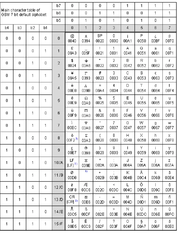
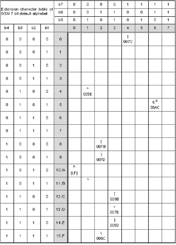
Figure 1.1: Main character table of GSM 7 bit default alphabet... 23 Figure 1.2: Extension character table of GSM 7 bit default alphabet... 24 Figure 19.1: SPI modes selectable on SPI ... 391
List of Figures
1. Introduction
1.
Introduction
1.1
Scope of the document
This document presents the AT Command Set for BGS5 GSM Mobile Engine, Release 01.100.
Before using the BGS5 or upgrading to a new firmware version please read the latest product information pro-vided in "BGS5 Release Notes, Version 01.100".
More information is available at http://m2m.gemalto.com/.
DISCLAIMER:
AT commands or parameters not documented in this document are subject to change and reserved for future use. Gemalto M2M GmbH reserves the right to modify or even eliminate these options in later releases.
1.2
Related documents
[1] BGS5 Release Notes, Version 01.100
[2] BGS5 Hardware Interface Description, Version 01.100 [3] Java User's Guide
[4] Multiplexer User's Guide
[5] 3GPP TS 27.010 (descendant of 3GPP TS 07.10): Terminal Equipment to User Equipment (TE-UE)
multi-plexer protocol
[6] Multiplex Driver Developer's Guide [7] Multiplex Driver Installation Guide
[8] Application Note 02: Audio Interface Design [9] Application Note 16: Updating BGS5 Firmware
[10] 3GPP TR 21.905 (descendant of 3GPP TR 01.04): Vocabulary for 3GPP Specifications
[11] International Organization for Standardization (ISO): ISO/IEC10646: Universal Multiple-Octet Coded
Char-acter Set (UCS) - Part 1: Architecture and Basic Multilingual Plane.
This international standard is closely related to the Unicode Standard published by the Unicode Consortium
[12] The Unicode Consortium: Mapping of ETSI GSM 03.38 7-bit default alphabet characters into Unicode
[.TXT!]
[13] ITU-T V.24 List of definitions for interchange circuits between data terminal equipment (DTE) and data
cir-cuit-terminating equipment (DCE)
[14] ITU-T V.250 Serial asynchronous automatic dialling and control
[15] 3GPP TS 11.11: Specification of the Subscriber Identity Module - Mobile Equipment (SIM - ME) interface [16] 3GPP TS 31.101: UICC-terminal interface; Physical and logical characteristics
[17] 3GPP TS 31.102: UICC-terminal interface; Physical and logical characteristics
[18] 3GPP TS 11.14: Specification of the SIM Application Toolkit for the Subscriber Identity Module - Mobile
Equipment (SIM - ME) interface
[19] 3GPP TS 31.111: Universal Subscriber Identity Module (USIM) Application Toolkit (USAT) [20] ETSI TS 102 223: Smart Cards; Card Application Toolkit (CAT)
[21] 3GPP TS 22.002 (descendant of 3GPP TS 22.02): Circuit Bearer Services (BS) supported by a Public Land
Mobile Network (PLMN)
[22] 3GPP TS 22.004 (descendant of 3GPP TS 02.04): General on supplementary services
[23] 3GPP TS 22.030 (descendant of 3GPP TS 02.30): Man-Machine Interface (MMI) of the Mobile Station (MS) [24] 3GPP TS 22.060 (descendant of 3GPP TS 02.60): General Packet Radio Service (GPRS); Service
descrip-tion; Stage 1
[25] 3GPP TS 23.060 (descendant of 3GPP TS 03.60): General Packet Radio Service (GPRS); Service
descrip-tion; Stage 2
[26] 3GPP TS 22.081 (descendant of 3GPP TS 02.81): Line Identification Supplementary Services; Stage 1 [27] 3GPP TS 22.082 (descendant of 3GPP TS 02.82): Call Forwarding (CF) Supplementary Services; Stage 1 [28] 3GPP TS 22.083 (descendant of 3GPP TS 02.83): Call Waiting (CW) and Call Holding (HOLD);
Supple-mentary Services; Stage 1
[29] 3GPP TS 22.085 (descendant of 3GPP TS 02.85): Closed User Group (CUG) supplementary services;
Stage 1
[30] 3GPP TS 22.088 (descendant of 3GPP TS 02.88): Call Barring (CB) supplementary services; Stage 1 [31] 3GPP TS 22.090 (descendant of 3GPP TS 02.90): Unstructured Supplementary Service Data (USSD);
Stage 1
[32] 3GPP TS 23.038 (descendant of 3GPP TS 03.38): Alphabets and language specific information
[33] 3GPP TS 23.040 (descendant of 3GPP TS 03.40): Technical realization of the Short Message Service
(SMS)
Cinterion
BGS5 AT Command Set
1.2 Related documents
[35] 3GPP TS 23.107: Quality of Service (QoS) concept and architecture
[36] 3GPP TS 24.011 (descendant of 3GPP TS 04.11): Point-to-Point (PP) Short Message Service (SMS)
sup-port on mobile radio interface
[37] 3GPP TS 24.008 (descendant of 3GPP TS 04.08): Mobile radio interface Layer 3 specification; Core
net-work protocols; Stage 3
[38] 3GPP TS 24.080 (descendant of 3GPP TS 04.80): Mobile radio interface layer 3 supplementary services
specification; Formats and coding
[39] 3GPP TS 25.331 Radio Resource Control (RRC)
[40] 3GPP TS 27.005 (descendant of 3GPP TS 07.05): Use of Data Terminal Equipment - Data Circuit
terminat-ing Equipment (DTE - DCE) interface for Short Message Service (SMS) and Cell Broadcast Service (CBS)
[41] 3GPP TS 27.007 (descendant of 3GPP TS 07.07): AT command set for User Equipment (UE)
[42] 3GPP TS 27.060 (descendant of 3GPP TS 07.60): Mobile Station (MS) supporting Packet Switched
Ser-vices
[43] 3GPP TS 22.101 (descendant of 3GPP TS 02.07 and 3GPP TS 02.40): Service principles [44] Common PCN Handset Specification (CPHS) v4.2 [.ZIP!]
[45] 3GPP TS 45.008 (descendant of GSM 05.08): Radio subsystem link control [46] USB Language Identifiers (LANGIDs) [.PDF!].
1.3
Glossary of Terms
Acronym Definition
GSM Global System for Mobile Communications ...
PLMN Public Land Mobile Network ...
Cinterion
BGS5 AT Command Set
1.4 Document Conventions
1.4
Document Conventions
Throughout this document BGS5 is also referred to as GSM Mobile Engine or short ME, MS (Mobile Station) or Mobile Terminal (MT). In related documents the equivalent terms DCE (Data Communication Equipment), fac-simile DCE or FAX modem may be found.
AT commands are used to control the BGS5. The controlling device is referred to as Customer Application or short TE. Related documents may use the equivalent term DTE (Data Terminal Equipment).
All abbreviations and acronyms used throughout this document are based on GSM or 3GPP specifications. For definitions please refer to 3GPP TR 21.905 [10].
1.4.1
Quick Reference Table
Each AT command description includes a table similar to the example shown below. The table is intended as a quick reference to indicate the following functions:
Example:
PIN: Is the AT command PIN protected?
+
Yes-
No±
Usage is dependent on conditions specified for the command, or not all command types are PIN protected (for example write command PIN protected, read command not).Note: The table provided in Section 21.3, Available AT Commands and Dependency on SIM PIN uses the same symbols.
Is the AT command supported in AIRPLANE mode?+
Yes-
No±
In AIRPLANE mode, not all described functions are available. For example, the test or read com-mand is usable, the write or execute comcom-mand is not. Furthermore, only some of the listed parameters can be changed in AIRPLANE mode. A typical example is AT^SCFG that controlsdif-ferent features.
Last: If commands are concatenated, this AT command must be the last one.
+
Yes-
NoNote: See also Section 1.5, AT Command Syntax for details on concatenated AT commands.
PIN
Last-1.4.2
Superscript notation for parameters and values
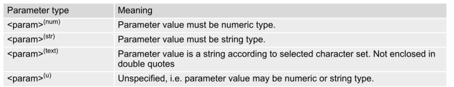
Table 1.1: Symbols used to mark the type of parameters
Table 1.2: Symbols used to indicate storage options or correlations with other commands
Table 1.3: Symbols used to mark different types of default values of parameters
Parameter type Meaning
<param>(num) Parameter value must be numeric type. <param>(str) Parameter value must be string type.
<param>(text) Parameter value is a string according to selected character set. Not enclosed in double quotes
<param>(u) Unspecified, i.e. parameter value may be numeric or string type.
Parameter option Meaning
<param>(+CSCS) Parameter value has to be (is) coded according to current setting of
<chset> (see
AT+CSCS for details)
<param>(&W) Parameter value is stored to user profile in non-volatile memory after executing
AT&W
<param>(NV) Parameter is stored in non-volatile memory.
Value option Meaning
[x] Default value set if parameter is omitted. x(&F) Factory value restored by AT&F
x(P) Powerup value of a parameter not stored in non-volatile memory.
x(D) Delivery value of a parameter which may be overridden from non-volatile setting (refer to symbol (NV) and symbol (&W) above).
Cinterion
BGS5 AT Command Set
1.5 AT Command Syntax
1.5
AT Command Syntax
The "AT" or "at" prefix must be set at the beginning of each command line. To terminate a command line enter <CR>. Commands are usually followed by a response that includes "<CR><LF><response><CR><LF>". Throughout this document, only the responses are presented, <CR><LF> are omitted intentionally.
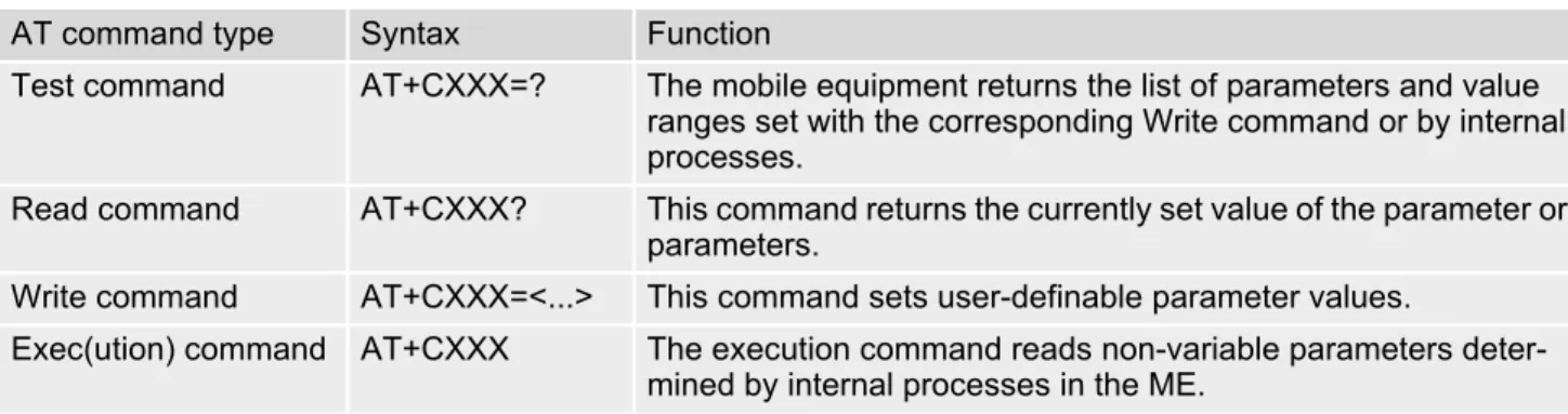
Table 1.4: Types of AT commands and responses
1.5.1
Using Parameters
• Multiple parameters are separated by commas. This applies to write commands, command responses, URCs and result codes. Please note that throughout this document spaces behind commas may be added for better readability.
• Optional parameters are enclosed in square brackets. If optional parameters are omitted, the current settings are used until you change them.
• Optional parameters or subparameters can be omitted unless they are followed by other parameters. If you want to omit a parameter in the middle of a string it must be replaced by a comma. See also example 1. • A parameter value enclosed in square brackets represents the value that will be used if an optional parameter
is omitted.
• When the parameter is a character string, e.g. <text> or <number>, the string must be enclosed in quotation
marks, e.g. "Charlie Brown" or "+49030xxxx". Symbols in quotation marks will be recognized as strings. • All spaces will be ignored when using strings without quotation marks.
• It is possible to omit the leading zeros of strings which represent numbers.
• If an optional parameter of a ITU-T V.250 command is omitted, its value is assumed to be 0.
Example 1: Omitting parameters in the middle of a string
Example 2: Using default parameter values for optional parameters
AT command type Syntax Function
Test command AT+CXXX=? The mobile equipment returns the list of parameters and value ranges set with the corresponding Write command or by internal processes.
Read command AT+CXXX? This command returns the currently set value of the parameter or parameters.
Write command AT+CXXX=<...> This command sets user-definable parameter values.
Exec(ution) command AT+CXXX The execution command reads non-variable parameters deter-mined by internal processes in the ME.
AT+CCUG? Query current setting
+CCUG: 1,10,1 OK
AT+CCUG=,9 Set only the middle parameter
OK
AT+CCUG? Query new setting
+CCUG: 1,9,1 OK
AT+CREG= Setting default values for AT+CREG.
OK
AT+CREG? Query settings.
+CREG: 0,0 AT+CREG default values are set. OK
1.5.2
Concatenating AT Commands
Concatenating AT commands on the same line is possible, though not recommended because of restrictions listed below (for more details see ITU-T V.250 [14]).
When concatenating AT commands you need to enter the "AT" or "at" prefix only once at the beginning of a mand line. Basic commands (i.e., ITU-T V.250 commands) are concatenated without delimiter. Extended com-mands (i.e., comcom-mands starting with AT+ or AT^) use a semicolon as delimiter.
Disadvantages and restrictions:
• There is no way to control the minimum time to wait between finishing an AT command and sending the next one. Please refer to Section 1.6, Communication between Customer Application and BGS5 for details about timing.
• The sequence of processing the AT commands may be different from the sequential order of command input. • Many AT commands cannot be concatenated (see list below). Concatenating these commands might end up
with an error result code, or leads to an unexpected order of responses.
1.5.3
Application Design Considerations
When designing your application keep in mind that parameters given in AT command responses, result codes and unsolicited result codes are only separated by commas with no spaces in between. Please take care that your application ignores any additional spaces that may, nevertheless, be inserted in some AT command responses, result codes and unsolicited result codes provided by BGS5.
AT command type Comment
3GPP TS 27.007 commands Cannot be concatenated with extended commands (prefix AT^S)
3GPP TS 27.005 commands (SMS) To be used standalone Commands starting with AT& To be used standalone
Cinterion
BGS5 AT Command Set
1.6 Communication between Customer Application and BGS5
1.6
Communication between Customer Application and BGS5
After power-up or restart ensure that the ME is in ready state before trying to send any AT command or data. For detailed information on timing conditions, signal states and particularly the startup behavior of the BGS5's signal lines refer to the Hardware Interface Description [2].
Leaving hardware flow control unconsidered the Customer Application (TE) is coupled with the BGS5 (ME) via a receive and a transmit line.
Since both lines are driven by independent devices collisions may (and will) happen. For example, if the TE issues an AT command and the BGS5 starts sending a URC. This will probably cause the TE to misinterpret the URC being part of the AT command's response. To avoid this conflict the following measures must be taken: • If an AT command is finished (with "OK" or "ERROR") the TE shall always wait at least 100 ms before sending
the next one. This applies to bit rates of 9600 bps or higher (see AT+IPR). At bit rates below 9600 bps the
delay must be longer: 300 ms at 1200 bps, and 500 ms at 300 bps.
The pause between two AT commands gives the BGS5 the opportunity to the transmission of pending URCs and get necessary service.
• The TE shall communicate with the BGS5 using activated echo (ATE1), i.e. the BGS5 echoes characters
received from the TE.
Hence, when the TE receives the echo of the first character "A" of the AT command just sent by itself it has control both over the receive and the transmit paths.
Using Backspace at command line:
• As the standard GSM alphabet does not provide a backspace functionality the BGS5 is designed to use the character "08" (hex 0x08) as backspace for command line input. This allows the user to easily erase the last character when writing an AT command. On the other hand, this solution requires entering the escape sequence \08 for writing the "ò" character in GSM character string parameters.
• If command echo is enabled (ATE1) Backspace may cause 08 - 32 - 08 (decimal) character sequence or no
1.7
Supported character sets
BGS5 supports two character sets: GSM 7 bit, also referred to as GSM alphabet or SMS alphabet (3GPP TS
23.038 [32]) and UCS216 bit (ISO-10646 [11]). See AT+CSCS for information about selecting the character set.
Character tables can be found below.
Explanation of terms • Escape Character
There are two types of escape sequences which lead to an alternative interpretation on subsequent charac-ters by the ME:
- AT command interface
Escape sequences starting with character value 0x5C are used for the ME's non-UCS2 input and output. - GSM 7 bit default alphabet
The escape sequence used within a text coded in the GSM 7 bit default alphabet is starting with character value 0x1B and needs to be correctly interpreted by the TE, both for character input and output. To the BGS5, an escape sequence appears like any other byte received or sent.
For SMS user data input after the prompt '>' in text mode (AT+CMGF)=1 and AT+CSCS="GSM" the character
0x1A is interpreted as 'CTRL-Z'. The character 0x1B (interpreted as 'ESC') as well as the escape character 0x5C (is interpreted as 'Ö'), therefore both escape mechanisms are not supported in this case.
• TE Character Set
The character set currently used by the Customer Application is selected with AT+CSCS. It is recommended
to select UCS2 setting. • Data Coding Scheme (DCS)
DCS is part of a short message and is saved on the SIM. When writing a short message to the SIM in text mode, the DCS stored with AT+CSMP is used and determines the coded character set.
• International Reference Alphabet (IRA)
The International Reference Alphabet is equivalent to ASCII (American Standard Code for Information Inter-change) and ISO 646, i.e. it defines a 7-bit coded character set. The mapping can be obtained from the char-acter set tables below (UCS2 values 0x0000 to 0x007F).
When you enter characters that are not valid characters of the supported alphabets the behavior is undefined. If GSM alphabet is selected, all characters sent over the serial line (between TE and ME) must be in the range from 0 to 127 (7 bit range).
Note: If the ME is configured for GSM alphabet, but the Customer Application (TE) uses ASCII, bear in mind that some characters have different code values, such as the following:
• "@" character with GSM alphabet value 0 is not displayable by an ASCII terminal program, e.g. Microsoft© Hyperterminal®.
• "@" character with GSM alphabet value 0 will terminate any C string! This is because value 0 is defined as C string end tag. Therefore, the GSM Null character will cause problems on application level when using 'C'-functions, e.g. "strlen()". Using an escape sequence as shown in the table below solves the problem. By the way, this may be the reason why even network providers sometimes replace '@' with "@=*" in their SIM appli-cation.
• Some other characters of the GSM alphabet may be misinterpreted by an ASCII terminal program. For exam-ple, GSM "ö" (as in "Börse") is assumed to be "|" in ASCII, thus resulting in "B|rse". This is because in both alphabets there are different characters assigned to value 7C (hexadecimal).
If the TE sends characters differently coded or undefined in ASCII or GSM (e.g. Ä, Ö, Ü) it is possible to use escape sequences. The ME's input parser translates the escape sequence to the corresponding GSM character value.
Note:
The ME also uses escape sequences for its non-UCS2 output: Quotation mark (") and the escape character itself (\, respectively Ö in GSM alphabet) are converted, as well as all characters with a value below 32 (hexadecimal 0x20).
Hence, the input parser of the Customer Application needs to be able to translate escape sequences back to the corresponding character of the currently used alphabet.
Cinterion
BGS5 AT Command Set
1.7 Supported character sets
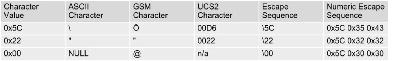
Table 1.5: Exemplary escape sequences generated by BGS5 for its non-UCS2 output
Usually terminal programs are not able to recognize escape sequences, and thus, handle them as normal char-acters.
To prevent misinterpretation of control characters or special characters it is recommended to always use USC2 alphabet and PDU mode.
Character
Value ASCIICharacter GSMCharacter UCS2Character EscapeSequence Numeric EscapeSequence
0x5C \ Ö 00D6 \5C 0x5C 0x35 0x43
0x22 " " 0022 \22 0x5C 0x32 0x32
1.7.1
GSM alphabet tables and UCS2 character values
This section provides tables for the GSM default alphabet (3GPP TS 23.038 [32]) supported by the BGS5. Below any GSM character find the corresponding two byte character value of the UCS2 alphabet. For details refer to "ETSI GSM 03.38 mapping into Unicode" [12].
1) This code is an escape to the following extension of the 7 bit default alphabet table.
2) This code is not a printable character and therefore not defined for the UCS2 alphabet. It shall be treated as the accom-panying control character.
3) See Section 1.6 for further details on using backspace and "ò" character.
Cinterion
BGS5 AT Command Set
1.7 Supported character sets
1) This code value is reserved for the extension to another extension table. On receipt of this code, a receiving entity shall display a space until another extension table is defined.
2) This code represents the EURO currency symbol. The code value is the one used for the character 'e'. Therefore a receiv-ing entity which is incapable of displayreceiv-ing the EURO currency symbol will display the character 'e' instead.
3) This code is defined as a Page Break character and may be used for example in compressed CBS messages. Any mobile which does not understand the 7 bit default alphabet table extension mechanism will treat this character as Line Feed.
If the Customer Application receives a code where a symbol is not represented in Figure 1.2, Extension character table of GSM 7 bit default alphabet it shall display the character shown in the main GSM 7 bit default alphabet table (see Figure 1.1, Main character table of GSM 7 bit default alphabet).
1.7.2
UCS2 and GSM character coding and conversion
This section provides basic information on how to handle input and output character conversion, e.g. for SMS text mode, if the character representation of ME and Customer Application differ, i.e. if the Data Coding Scheme and the TE character set use different mappings.
1.7.2.1
Output of SIM data (ME to TE)
Note: The ratio of SIM bytes to output bytes is given in parentheses.
Case 1
Every GSM character is sent to the TE as it is (8-bit value with highest bit set to zero). Example: 47'H, 53'H, 4D'H 47'H, 53'H, 4D'H, displayed as "GSM"
Case 2
Every data byte is sent to the TE as 2 IRA characters each representing a halfbyte. Example: B8'H (184 decimal) 42'H, 38'H, displayed as "B8"
Case 3
Every 16-bit UCS2 value is sent to the TE as 4 IRA characters.
Example: C4xA7'H (50343 decimal) 43'H, 34'H, 41'H, 37'H, displayed as "C4A7"
Problem: An odd number of bytes leads to an error because there are always two bytes needed for each USC2 character
Case 4
Every GSM character is sent to the TE as 4 IRA characters to show UCS2 in text mode. Example: 41'H ("A") 30'H, 30'H, 34'H, 31'H, displayed as "0041"
Case 5
Every data byte is sent to the TE as IRA representation of UCS2 (similar to case 4). Example: B2'H 30'H, 30'H, 42'H, 32'H, displayed as "00B2"
Case 6
Every 16-bit value is sent to the TE as IRA representation of it. It is assumed that number of bytes is even. Example: C3x46'H 43'H, 33'H, 34'H, 36'H, displayed as "C346"
Used character set DCS = 7 bit
GSM DCS = 8 bitData DCS = 16 bitUCS2
GSM Case 1
GSM (1:1) Case 28 bit to IRA (1:2) Case 3UCS2 to IRA (2:4)
UCS2 Case 4
Cinterion
BGS5 AT Command Set
1.7 Supported character sets
1.7.2.2
Input of SIM data (TE to ME)
Note: The ratio between the number of input characters and bytes stored on the SIM is given in parentheses.
Case 1
Every character is sent from TE to ME as GSM character (or ASCII with standard terminal emulation, e.g. Hyper-terminal®).
Character value must be in range from 0 to 127 because of 7-bit GSM alphabet.
To reach maximum SMS text length of 160 characters in 140 bytes space characters will be compressed on SIM. This must be set using the parameter <dcs> of AT+CSMP (add 64).
Example: "ABCDEFGH" typed is sent and stored uncompressed as 4142434445464748'H (stored com-pressed as 41E19058341E91'H)
Case 2
Every data byte is sent as 2 IRA characters.
Maximum text length is 280 IRA characters which will be converted into 140 bytes SMS binary user data Example: "C8" typed is sent as 43'H, 38'H stored as C8'H
Case 3
Every 16-bit value is sent as 4 IRA characters.
Maximum text length is 280 IRA characters which will be converted into 70 UCS2 characters (16-bit each) Number of IRA characters must be a multiple of four because always 4 half bytes are needed for a 16-bit value Example: "D2C8" typed is sent as 44'H, 32'H, 43'H, 38'H stored as D2C8'H
Case 4
Every GSM character is sent as 4 IRA characters representing one UCS2 character. Example: To store text "ABC" using UCS2 character set you have to type "004100420043".
This is sent as 30'H,30'H,34'H,31'H, 30'H,30'H,34'H,32'H, 30'H,30'H,34'H,33'H detected as IRA representa-tion of 3 UCS2 characters, converted to GSM character set and stored as 41'H, 42'H, 43'H.
Maximum input is 640 IRA characters representing 160 UCS2 characters when compression is active. These are converted to 160 GSM 7-bit characters.
Without compression only 140 GSM characters can be stored which are put in as 560 IRA characters. Values of UCS2 characters must be smaller than 80'H (128 decimal) to be valid GSM characters. Number of IRA characters must be a multiple of four. Problems:
• "41" Error, there are four IRA characters (two bytes) needed • "0000" Error, not an UCS2 character
• "4142" Error, value of UCS2 character > 7F'H • "008B" Error, value of UCS2 character > 7F'H This affects the maximum input length of a string)
Case 5
Every UCS2 character is sent as 4 IRA characters and is converted into two 8-bit values. This means that the first two characters have to be '00'.
Example: UCS2 character 009F'H typed as "009F" is sent as 30'H,30'H,39'H,46'H converted into 8-bit value 9F'H.
Maximum number of UCS2 characters is 140 which are represented by 560 IRA characters. Number of IRA char-acters must be a multiple of four.
Case 6
Every UCS2 character is sent as 4 IRA characters each and is converted into a 16-bit value again.
Example: UCS2 character 9F3A'H typed as "9F3A" is sent as 39'H,46'H,33'H,41'H converted into 9F3A'H. Maximum number of UCS2 characters is 70 which are represented by 280 IRA characters. Number of IRA char-acters must be a multiple of four.
Invalid UCS2 values must be prevented. Used character set DCS = 7 bit
GSM DCS = 8 bitData DCS = 16 bitUCS2
GSM Case 1
GSM (1:1) Case 2IRA to 8 bit (2:1) Case 3IRA to 16 bit (4:2)
UCS2 Case 4
1.8
Unsolicited Result Code Presentation
URC stands for Unsolicited Result Code and is a report message issued by the ME without being requested by the TE, i.e. a URC is issued automatically when a certain event occurs. Hence, a URC is not issued as part of the response related to an executed AT command.
Typical events leading to URCs are incoming calls ("RING"), waiting calls, received short messages, changes in temperature, network registration etc.
For most of these messages, the ME needs to be configured whether or not to send a URC. Descriptions of these URCs are provided with the associated AT command. URCs which are not user definable are described in Sec-tion 1.8.1, Common URCs. A summary of all URCs can be found in Section 21.7, Summary of Unsolicited
Result Codes (URC).
Important: If the interface used for URC output is reserved by an active data connection or a long running AT
command, URCs are buffered internally and will be issued after the interface becomes idle again. A pending URC will be signaled on the URC output interface via RING line. This allows to systematically suspend any longer data connection (refer +++ and ATO) to check for pending URCs after being signaled!
For detailed information regarding configuration of URC signaling refer to AT^SCFG, "URC/Ringline",
<urcRin-glineCfg>.
Parameter Description
200 URC will be send 40 seconds after syste-up when the JRC midlet was not tried to start (no autostart, no midlet at all, whatever). Used to see in logs, that midlet is not running, as example.
201 The JRC midlet was started, but did not succeed to full init itself within a (JRC midlet defined) timeout. 5 seconds after this URC, the module will restart. 202 The midlet was tried to start 5x, but was restarted (with ^SYSINFO: 201). Now,
the JRC midlet start was cancelled. No JRC midlet is running. A shutdown timer of 10 minutes is started. After this timer, the module will be switched off.
1.8.1
Common URCs
This section describes all URCs not associated to a certain AT command. They cannot be defined by the user and appear automatically when the conditions described below occur.
URC 1
^SYSLOADING
Indicates that the ME is in the process of starting up. Do not enter AT commands until the "^SYSSTART" URC
has shown up.
URC 2
^SYSSTART
Indicates that the ME has been restarted to Normal mode or Airplane mode and is ready to operate. For Normal and Airplane mode see AT+CFUN.
Note: Autobaud mode (see AT+IPR) requires an "AT" or "at" string be given after restarting the ME. This
enables the ME to detect the bit rate set in the TE. After detecting the bit rate the ME will send the "
^SYS-START" URC.
Cinterion
BGS5 AT Command Set
1.8 Unsolicited Result Code Presentation
URC 3
+PBREADY
After SIM PIN authentication has completed this URC indicates that the ME has completed reading data from the SIM and that phonebook and SMS functions are ready for read and write operation.
Any attempt to use phonebook or SIM PIN dependent SMS AT commands before the ME has finished reading SIM data will be denied with error codes, such as "+CME ERROR: SIM busy" or "+CMS ERROR: SIM busy".
URC 4
^SYSINFO: <info>
1.9
Errors and Messages
The command result codes "+CME ERROR: <err>" and "+CMS ERROR: <err>" indicate errors related to mobile equipment or network functionality.
The format of <err> can be either numeric or verbose and is selectable via AT+CMEE.
A result error code terminates the execution of the command and prevents the execution of all remaining com-mands that may follow on the same command line. If so, neither "ERROR" nor "OK" result codes are returned for these commands. A 30 seconds timeout will deliver "ERROR" when the input of a command is not complete.
Using the wrong command syntax may result in errors: For example, using the execute command syntax although the command has no execute format, causes "ERROR" to be returned. Likewise, using the write com-mand syntax although the comcom-mand has no write format causes "+CME ERROR: <err>" to be returned.
See also:
• Section 2.10.1, CME/CMS Error Code Overview • Section 2.5.1, Verbose and numeric result codes • Section 3.1, AT+CEER
2. Configuration Commands
2.
Configuration Commands
The AT Commands described in this chapter allow the external application to determine the BGS5's behaviour under various conditions.
2.1
AT&F Reset AT Command Settings to Factory Default Values
AT&F resets AT command settings to their factory default values.
For a list of affected parameters refer to Section 21.6, Factory Default Settings Restorable with
AT&F.
Syntax
Parameter Description
[0] Reset parameters in Section 21.6, Factory Default Settings
Restor-able with AT&F to their factory default values.
Exec Command AT&F[<value>]
Response(s)
OK
PIN
Last Reference(s)- + - V.250
2.2
AT&V Display current configuration
AT&V returns the current parameter setting. The configuration varies depending on whether or not PIN
authen-tication has been done.
Syntax
Parameter Description
[0] Profile number Note
• The parameter of AT+CSDH will only be displayed in SMS Text mode, see AT+CMGF.
Exec Command AT&V[<value>]
Response(s)
ACTIVE PROFILE:
... (see Section 2.2.1, AT&V responses) OK
PIN
Last Reference(s)- + - V.250
Cinterion
BGS5 AT Command Set
2.2 AT&V
2.2.1
AT&V responses
The following tables show four different kinds of responses depending on whether or not the PIN is entered.
PIN authentication done No PIN authentication
ACTIVE PROFILE:
E1 Q0 V1 X4 &C1 &D2 &S0 \Q0
S0:000 S3:013 S4:010 S5:008 S6:000 S7:060 S8:000 S10:002 +CBST: 7,0,1 +CRLP: 61,61,78,6 +CR: 0 +CRC: 0 +CMGF: 1 +CSDH: 0 +CNMI: 0,0,0,0,1 +CMEE: 2 +CSMS: 0,1,1,1 +CREG: 0,1 +CLIP: 0,2 +COPS: 0,0,"operator",0 +CGSMS: 3 OK ACTIVE PROFILE:
E1 Q0 V1 X4 &C1 &D2 &S0 \Q0
S0:000 S3:013 S4:010 S5:008 S6:000 S7:060 S8:000 S10:002 +CBST: 7,0,1 +CRLP: 61,61,78,6 +CR: 0 OK
2.3
AT&W Store AT Command Settings to User Defined Profile
AT&W stores the current AT command settings to a user defined profile in non-volatile memory of BGS5. The AT
command settings will automatically be restored from the user defined profile during power-up or if ATZ is used.
AT&F restores AT command factory default settings. Hence, until first use of AT&W, ATZ works as AT&F.
A list of parameters stored to the user profile can be found at Section 21.5, AT Command Settings storable
with AT&W.
Syntax
Parameter Description
[0] User Profile Number
Exec Command AT&W[<value>]
Response(s)
OK ERROR
+CME ERROR: <err>
PIN
Last Reference(s)- + - V.250
Cinterion
BGS5 AT Command Set
2.4 ATQ
2.4
ATQ Result Code Presentation Mode
ATQ controls if the BGS5 transmits any result code to the TE. Other information text transmitted as response is
not affected.
Syntax
Parameter Description
Result Code Presentation Mode.
It is not recommended to change this value.
[0](&F)(D) ME transmits result code.
1 Result codes are suppressed and not transmitted.
Exec Command ATQ[<n>] Response(s) If <n>=0: OK If <n>=1: (none)
PIN
Last Reference(s)- + - V.250
2.5
ATV Result code format mode
This command determines the contents of header and trailer transmitted with AT command result codes and information responses. Possible responses are described in Section 2.5.1, Verbose and numeric result codes.
Syntax
Parameter Description
[0] Information response: <text><CR><LF> Short result code format: <numeric code><CR> 1(&F)(D) Information response: <CR><LF><text><CR><LF>
Long result code format: <CR><LF><verbose code><CR><LF>
2.5.1
Verbose and numeric result codes
Exec CommandATV[<value>]
Response(s)
OK ERROR
PIN
Last Reference(s)- + - ITU-T V.250 [14]
<value>(num)(&V)(&W)
Verbose format Numeric format Meaning
OK 0 command executed, no errors
CONNECT 1 link established
RING 2 ring detected
NO CARRIER 3 link not established or disconnected
ERROR 4 invalid command or command line too long
NO DIALTONE 6 no dial tone, dialling impossible, wrong mode
BUSY 7 remote station busy
NO ANSWER 8 no answer
CONNECT 2400/RLP 10 link with 2400 bps
CONNECT 4800/RLP 11 link with 4800 bps
Cinterion
BGS5 AT Command Set
2.6 ATX
2.6
ATX CONNECT Result Code Format
ATX determines whether or not the BGS5 transmits particular result codes to the TE. It also controls whether or
not the ME verifies the presence of a dial tone when it begins dialing, and if engaged tone (busy signal) detection is enabled.
Syntax
Parameter Description
[0] CONNECT result code only returned. Dial tone and busy detection are dis-abled.
1 CONNECT <text> result code only returned. Dial tone and busy detection are
both disabled.
2 CONNECT <text> result code returned. Dial tone detection is enabled, busy
detection is disabled.
3 CONNECT <text> result code returned. Dial tone detection is disabled, busy
detection is enabled.
4(&F) CONNECT <text> result code returned. Dial tone and busy detection are
both enabled. Exec Command ATX[<value>] Response(s) OK ERROR
PIN
Last Reference(s)- + - V.250
2.7
ATZ Restore AT Command Settings from User Defined Profile
ATZ is supported for compatibility with other products. The command command restores the user defined profile
on user request.
Syntax
Parameter Description
1...65535 The stored profile will be restored with any valid number.
Exec Command
ATZ[<value>]
Response(s)
OK
PIN
Last Reference(s)- + - V.250
Cinterion
BGS5 AT Command Set
2.8 AT+CFUN
2.8
AT+CFUN Functionality Level
AT+CFUN controls BGS5's functionality level. It can also be used to reset the ME.
Syntax
Parameter Description
0 Switch off ME. ME returns OK followed by "^SHUTDOWN" URC.
See also AT^SMSO command.
1(D) Full functionality level.
4 Airplane mode.
Shut down TX and RX RF-circuits whereby BGS5 logs off from the network and switches to AT+COPS=2. All AT commands whose execution requires a radio
connection will return an error response (such as "NO CARRIER" or "+CME ERROR: NO NETWORK SERVICE". A list of AT commands supported during Airplane mode can be found in Section 21.4, Availability of AT
Com-mands Depending on Operating Mode of ME.
After leaving Airplane mode by setting AT+CFUN=1 the AT+COPS write
com-mand shall be used to register to a network once again.
Test Command AT+CFUN=? Response(s)
+CFUN: (list of supported <fun>s), (list of supported <rst>s)
OK ERROR
+CME ERROR: <err>
Read Command AT+CFUN? Response(s)
+CFUN: <power_mode>, <STK_mode>
OK ERROR
+CME ERROR: <err>
Write Command
AT+CFUN=<fun>[, <rst>]
Response(s)
OK ERROR
+CME ERROR: <err>
If <fun>= 0: OK ^SHUTDOWN If <rst>= 1: OK ^SYSSTART
PIN
Last Reference(s)- + - 3GPP TS 27.007 [41]
6 This mode was implemented in BGS5 Release 1 for activating the SAT inter-face. As of BGS5 Release 2 the mode is deprecated and no longer effective. SAT can now be used in Automatic or Explicit Response Mode depending on
AT^SSTA settings.
7 Reserved for future use.
8 Reserved for future use.
Parameter <rst> applies only to <fun> 1 and 4.
[0] ME switches to <fun> level without reset.
1 ME resets and restarts to full functionality level or Airplane mode, depending on given <fun> value. "^SYSSTART" URC indicates that the ME is ready to
operate.
Note: Autobaud mode (see AT+IPR) requires an "AT" or "at" string be given
after restart. This enables the ME to detect the bit rate set in the TE. After detecting the bit rate the ME will send the "^SYSSTART" URC.
1 ME is switched on
2 Invalid mode
4 Airplane mode
0 Deprecated. See above <fun> value 6.
6 Deprecated. See above <fun> value 6.
7 Reserved for future use.
8 Reserved for future use.
<rst>(num)
<power_mode>(num)
Cinterion
BGS5 AT Command Set
2.9 AT^SMSO
2.9
AT^SMSO Switch Off BGS5
AT^SMSO initiates BGS5's power-off procedure. Do not send any other AT command after this.
Low level of the ME's V180 signal and the URC "^SHUTDOWN" notify that the procedure has completed and the
ME has entered the POWER DOWN mode. Therefore, be sure not to disconnect the operating voltage until the V180 signal has gone low and until the URC "^SHUTDOWN" is displayed. Otherwise, you run the risk of losing
data. For further details on how to turn off the ME refer to [2]. If a fast switch off (see parameter <fso> in
AT^SCFG) is enabled, there is no reply like OK, ERROR or any "^SHUTDOWN" URC.
Syntax
Unsolicited Result Code
^SHUTDOWN
Indicates that the power-off procedure is finished and the module will be switched off in less than 1 second.
If <fso> is used to enable a fast ME switch off, there will be no "^SHUTDOWN" URC.
Note
• If <fso> is used to enable a fast ME switch off, flash access cycles (writing/deleting) will be finalized, but there
will no longer be any network deregistration, the current settings will not be saved and there will be no further output on the interfaces. All other jobs will be deleted and logical data consistance cannot be guaranteed.
Test Command AT^SMSO=? Response(s) OK Exec Command AT^SMSO Response(s) ^SMSO: MS OFF OK ERROR PIN
Last - + +2.10
AT+CMEE Error Message Format
AT+CMEE controls the format of error result codes that indicates errors related to BGS5 functionality. Format can
be selected between plain "ERROR" output, error numbers or verbose "+CME ERROR: <err>" and "+CMS ERROR: <err>" messages.
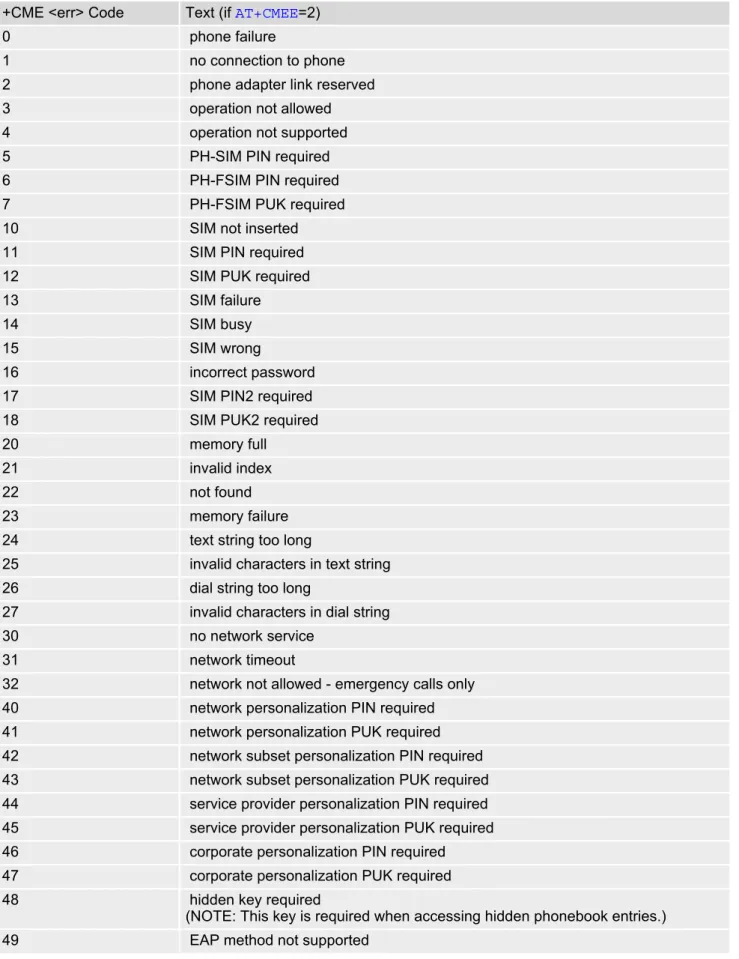
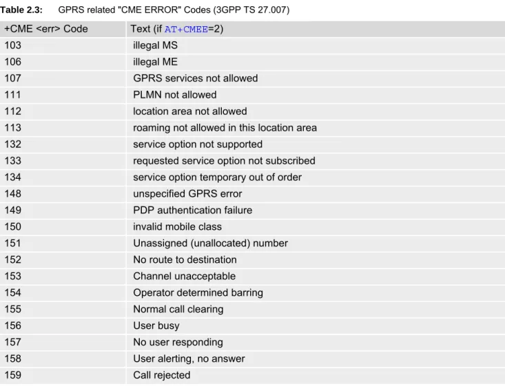
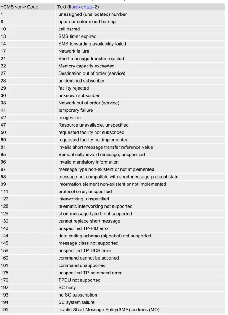
Possible error result codes are listed in Table 2.1, General "CME ERROR" Codes (3GPP TS 27.007), Table 2.2, General "CME ERROR" Codes (proprietary), Table 2.3, GPRS related "CME ERROR" Codes (3GPP TS 27.007) and Table 2.4, SMS related "CMS ERROR" Codes (3GPP TS 27.005).
Syntax
Parameter Description
0(&F)(D) Disable result code, i.e. only "ERROR" will be displayed.
1 Enable error result code with numeric values.
2 Enable error result code with verbose (string) values.
Example
To obtain enhanced error messages it is recommended to choose <errMode>=2.
Test Command AT+CMEE=? Response(s)
+CMEE: (list of supported<errMode>s)
OK Read Command AT+CMEE? Response(s) +CMEE: <errMode> OK Write Command AT+CMEE=<errMode> Response(s) OK ERROR
+CME ERROR: <err>
PIN
Last Reference(s)- + - 3GPP TS 27.007 [41], 3GPP TS
27.005 [40]
<errMode>(num)(&V)(&W)
AT+CMEE=2 OK
Cinterion
BGS5 AT Command Set
2.10 AT+CMEE
2.10.1
CME/CMS Error Code Overview
Table 2.1: General "CME ERROR" Codes (3GPP TS 27.007)
+CME <err> Code Text (if AT+CMEE=2)
0 phone failure
1 no connection to phone
2 phone adapter link reserved
3 operation not allowed
4 operation not supported
5 PH-SIM PIN required
6 PH-FSIM PIN required
7 PH-FSIM PUK required
10 SIM not inserted
11 SIM PIN required
12 SIM PUK required
13 SIM failure
14 SIM busy
15 SIM wrong
16 incorrect password
17 SIM PIN2 required
18 SIM PUK2 required
20 memory full
21 invalid index
22 not found
23 memory failure
24 text string too long
25 invalid characters in text string
26 dial string too long
27 invalid characters in dial string
30 no network service
31 network timeout
32 network not allowed - emergency calls only 40 network personalization PIN required 41 network personalization PUK required 42 network subset personalization PIN required 43 network subset personalization PUK required 44 service provider personalization PIN required 45 service provider personalization PUK required 46 corporate personalization PIN required 47 corporate personalization PUK required
48 hidden key required
(NOTE: This key is required when accessing hidden phonebook entries.)
Table 2.2: General "CME ERROR" Codes (proprietary)
Table 2.3: GPRS related "CME ERROR" Codes (3GPP TS 27.007)
50 Incorrect parameters
100 Unknown
256 operation temporary not allowed
257 call barred
261 SS not executed
500 CTS Handover on Progress
501 Cellular Protocol Stack Out of service state
502 CTS Unspecified Error
+CME <err> Code Text (if AT+CMEE=2)
615 network failure
616 network is down
639 service type not yet available
640 operation of service temporary not allowed
764 missing input value
765 invalid input value
767 operation failed
+CME <err> Code Text (if AT+CMEE=2)
103 illegal MS
106 illegal ME
107 GPRS services not allowed
111 PLMN not allowed
112 location area not allowed
113 roaming not allowed in this location area
132 service option not supported
133 requested service option not subscribed 134 service option temporary out of order
148 unspecified GPRS error
149 PDP authentication failure
150 invalid mobile class
151 Unassigned (unallocated) number
152 No route to destination
153 Channel unacceptable
154 Operator determined barring
155 Normal call clearing
156 User busy
157 No user responding
158 User alerting, no answer
159 Call rejected
Cinterion
BGS5 AT Command Set
2.10 AT+CMEE
160 Number changed
161 Non selected user clearing
162 Destination out of order
163 Invalid number format (incomplete number)
164 Facility rejected
165 Response to STATUS ENQUIRY
166 Normal, unspecified
167 No circuit/channel available
168 Network out of order
169 Temporary failure
170 Switching equipment congestion
171 Access information discarded
172 requested circuit/channel not available 173 Resources unavailable, unspecified 174 Quality of service unavailable 175 Requested facility not subscribed 176 Incoming calls barred within the CUG 177 Bearer capability not authorized
178 Bearer capability not presently available 179 Service or option not available, unspecified
180 Bearer service not implemented
181 ACM equal to or greater than ACMmax 182 Requested facility not implemented
183 Only restr. digital information bearer capability 184 Service or option not implemented, unspecified 185 Invalid transaction identifier value
186 User not member of CUG
187 Incompatible destination
188 Invalid transit network selection
189 Semantically incorrect message
190 Invalid mandatory information
191 Message type non-existent or not implemented 192 Message type not compatible with protocol state 193 Information element non-existent or not implemented
194 Conditional IE error
195 Message not compatible with protocol state
196 Recovery on timer expiry
197 Protocol error, unspecified
198 Interworking, unspecified
199 Number not allowed
200 CCBS possible
596 GPRS - invalid CID value
Table 2.4: SMS related "CMS ERROR" Codes (3GPP TS 27.005) +CMS <err> Code Text (if AT+CMEE=2)
1 unassigned (unallocated) number
8 operator determined barring
10 call barred
13 SMS timer expired
14 SMS forwarding availability failed
17 Network failure
21 Short message transfer rejected
22 Memory capacity exceeded
27 Destination out of order (service)
28 unidentified subscriber
29 facility rejected
30 unknown subscriber
38 Network out of order (service)
41 temporary failure
42 congestion
47 Resource unavailable, unspecified 50 requested facility not subscribed 69 requested facility not implemented
81 invalid short message transfer reference value 95 Semantically invalid message, unspecified
96 invalid mandatory information
97 message type non-existent or not implemented
98 message not compatible with short message protocol state 99 information element non-existent or not implemented 111 protocol error, unspecified
127 interworking, unspecified
128 telematic interworking not supported 129 short message type 0 not supported
130 cannot replace short message
143 unspecified TP-PID error
144 data coding scheme (alphabet) not supported
145 message class not supported
159 unspecified TP-DCS error
160 command cannot be actioned
161 command unsupported
175 unspecified TP-command error
176 TPDU not supported
192 SC busy
193 no SC subscription
194 SC system failure
Cinterion
BGS5 AT Command Set
2.10 AT+CMEE
196 Destination SME barred (MO)
197 SM rejected duplicated SM (MO)
198 TP-VPF (validity period format) not supported (MO) 199 TP-VP (validity period) not supported (MO)
208 (U