NETWORK MONITORING AND
ANALYSIS SYSTEMS
HARDWARE USER’S GUIDE
IQMediaMonitor Series M1
Singulus G1-T
Revision D
Copyright © 2004 IneoQuest Technologies, Inc.
All Rights Reserved. IneoQuest Technologies, Inc.
170 Forbes Boulevard Mansfield, Massachusetts 02048
Contents
Contents... i
1 Technical Support Information...1
1.1 Address and Telephone Numbers...1
1.2 Internet Addresses...1
2 General Safety Information...3
2.1 Safety terms ...3
2.2 General Precautions to avoid Injury...3
2.3 General Precautions to avoid Property Damage ...4
3 Introduction ...5
4 Singulus G1-T ...7
4.1 Laser Safety...7
4.2 Hardware and Connections...8
4.3 System Start-up ...10
4.3.1 System Management Port IP Configuration...10
4.3.2 Operating Mode Selection ...12
4.4 Specifications - Singulus G1-T...13
4.4.1 Power and Cooling...13
4.4.2 Reference Clock and Calibration ...13
4.4.3 Environmental...14
4.4.4 Regulatory Information ...14
4.4.5 Relevant Standards Compliance ...15
4.4.6 IneoQuest Part Numbers...16
4.5 Cleaning - Singulus G1-T...16
5 IQMediaMonitor Series M1...17
5.1 Laser Safety...17
5.2 Hardware and Connections...17
5.3 System Start-up ...19
5.3.1 System Management Port IP Configuration...20
5.3.2 Configure Using a Network Connection with a Web Browser ...20
5.3.3 Configure Using a Network Connection with a Telnet application ...20
5.4 Specifications - IQMediaMonitor Series M1...21
5.4.2 Reference Clock and Calibration ...22
5.4.3 Environmental ...22
5.4.4 Regulatory Information ...23
5.4.5 Relevant Standards Compliance ...23
5.4.6 IneoQuest Part Numbers...24
5.5 Cleaning - IQMediaMonitor Series M1 ...25
6 Configuration via Web (HTML) Pages ...27
6.1 Accessing unit with a Web Browser ...27
6.2 Configuring the Unit with the Web Browser ...29
6.2.1 System Status ...29
6.2.2 Network Statistics Pages ...30
6.2.3 System Configuration Pages...30
6.2.4 Monitor Configuration Pages ...30
6.2.5 Media Configuration Pages ...31
6.2.6 Configuration Management Pages ...31
6.2.7 Account Management Pages ...31
6.2.8 Factory Management Pages...31
7 SNMP Communications...33
8 IQFirmware and IQSoftwareSuite Updates ...35
8.1 Upgrading a unit using IQFirmwareUpdate...35
1 Technical Support Information
The IQController software and all support documentation are included on the CD that was shipped with the Singulus G1-T. Updated documentation, firmware and information for this and other products are available on the IneoQuest web site or FTP site.
1.1 Address and Telephone Numbers
Address, USA:
IneoQuest Technologies Inc. 170 Forbes Blvd.
Mansfield, MA 02048
Telephone, USA:
+1 508 339 2497
FAX Telephone Number, USA
+1 508 339 4727
1.2 Internet Addresses
E-Mail: techsupport@ineoquest.com URL: http://www.ineoquest.com FTP Server: ftp.ineoquest.com2 General Safety Information
Observe all safety precautions listed within this document to avoid injury and prevent damage to this product or any product connected to it. To avoid any hazardous conditions, use this product only as specified.
2.1 Safety terms
Safety statements throughout this manual are identified as follows:
WARNING!
Warning statements indicate conditions that could result in injury or loss of
life and describe how to avoid them.
CAUTION!
Caution statements indicate conditions that could result in damage to this
product or other property and describe how to avoid these problems.
2.2 General Precautions to avoid Injury
WARNING!
-
Do not operate in wet or damp environments or outside recommended
operating conditions. This product is intended for indoor use.
-
Only use power supply specified for this product with properly grounded
power outlet.
-
Do not operate this product in an explosive atmosphere.
-
Do not operate product if damaged. Have a qualified service person inspect
damaged equipment before use.
-
This test system is designed to be used for test, monitoring and analysis of
network equipment and systems. It is not intended to be used as a part of
any life support system, safety system or critical communications link.
2.3 General Precautions to avoid Property Damage
CAUTION!
-
Excessive electrostatic discharge may damage some components, take
precautions against electrostatic discharge.
-
Use care in handling, delicate connectors can be easily damaged.
-
Provide proper ventilation to prevent the product from overheating.
-
This test system is designed to be used for test, monitoring and analysis of
network equipment and systems. It is not intended to be used as a part of
any life support system, safety system or critical communications link.
3 Introduction
The Singulus and IQMediaMonitor platforms are based on state-of-the-art, reconfigurable FPGA technology. This means that you can find stability in an unstable market. As new standards, formats and protocols appear, IneoQuest products can be upgraded to future-proof you against test tool obsolescence.
This User's Guide covers hardware setup and configuration. Refer to separate application User's Guides for information about IneoQuest software that can be used with this hardware. IneoQuest applications that can be used to control and monitor the Singulus G1-T:
• IQMediaStimulus
• IQMediaMonitor
• IQMediaAnalyzer
• IQMediaController
IneoQuest applications that can be used to control and monitor the IQMediaMonitor:
• IQMediaMonitor
• IQMediaAnalyzer
Many configuration settings are stored within the Singulus or IQMediaMonitor test system. Storing configuration settings in the test system allows the system to list streams and report alarms consistently to many monitoring applications, such as IQMediaMonitor, running simultaneously at different locations.
The test systems use a Hypertext Transfer Protocol (HTTP) web browser interface for basic system status, configuration management, setting alarm thresholds and account
management. Overall control and transfer of detailed information is accomplished using Simple Network Management Protocol (SNMP).
4 Singulus G1-T
The Singulus G1-T platform is the “Swiss Army Knife” test tool for field troubleshooting, engineering and debugging of Triple Play networks. The Singulus G1-T is a multifunctional tool providing Network Traffic Stimulus, Analysis and Monitoring. The Singulus G1-T supports 10/100/1000 Ethernet with Built in / inline Hardware Sniffer ideal for Video over IP applications.
Singulus is based on Reconfigurable Technology that allows the user to configure the
hardware into alternate modes of operation. Singulus can be configured as an advanced, high powered network development and debug platform as well as a nimble, simple remote video monitoring platform. The user can easily switch operational modes using a simple web page interface served up by the Singulus.
IneoQuest applications that can be used to control and monitor the Singulus G1-T:
• IQMediaStimulus
• IQMediaMonitor
• IQMediaAnalyzer
• IQController
Note: Detailed information for each application can be found in separate Application
User's Guides.
4.1 Laser Safety
This monitoring and analysis system includes a Class 1 laser device that complies with CDRH 21 CFR 1040.10 and 1040.11 and the IEC 825-1.
WARNING!
-
User of controls, adjustments, and procedures other than those specified in User's Guide may result in hazardous laser radiation exposure.4.2 Hardware and Connections
Before attempting to set up the hardware, ensure that you received the following items with your shipment:
• 1, Singulus G1-T Chassis
• 1, 24V Power Supply
• 1, Power Cord (Regional Specific)
• 1, Serial Cable
• 1, CD-ROM containing IQSoftwareSuite applications and documentation In order to use the Singulus G1-T network test and analysis system, it must be correctly connected to the network and the host. Use the following figures and explanations to help you connect your system correctly.
Figure 1 shows the back of the Singulus G1-T network test and analysis system, and Figure 2 shows the front panel. The figures include reference numbers that correspond with the descriptions that follow.
Figure 1 Back of Singulus G1-T Chassis
Figure 2 Front of Singulus G1-T Chassis
The following list describes each of the numbered items on the front and back panels of the Singulus G1-T Unit.
1. DC Power Input connection. Connect the IneoQuest 24V power supply to this port on the back of the Singulus G1-T unit.
2. Chassis System Management Port Network Connection. Connect a standard 10/100 Base-Tx Ethernet cable to the port on the back of the unit. Use this port to connect the Singulus G1-T unit to your network for communication with IQMediaStimulus, IQMediaAnalyzer, IQController, IQMediaMonitor or another SNMP application running on the host
workstation. Be sure to set an appropriate IP configuration for this port before connecting to your network.
3. DC power On/Off and On-reset switch. Main power (AC) disconnect is accomplished by unplugging the power cord from the AC outlet.
4. Chassis Serial port. 9-pin D-subminiature serial port on the back of the unit. Use this port to connect to a host computer. This connection is required when assigning an IP address to the chassis during the first use. For proper operation, use the null modem cable that came with your Singulus G1-T. Serial communications settings are as follows: Bits per second: 9600, Data bits: 8, Parity: None, Stop bits: 1, Flow control: None.
5. ASI-Port, BNC (75 ohm) video port. The port can be used with video analysis equipment or video decoder and monitor. User selected IP video streams can be output to this port as an ASI transport stream.
6. Standard Device Under Test (DUT) Port 1. Used to connect Singulus to the DUT. Either a fiber cable to the Small Form-factor Pluggable (SFP) module or a copper CAT5 cable to the 10/100/1000 RJ45 connector can be used. The default configuration of this port is ARP disabled.
7. TAP Port 2. Used when the Singulus is connected in line and passes through the Tx and Rx data with optional filtering or is configured as a Remote Video Link (RVL) port. Either a fiber cable to the Small Form-factor Pluggable (SFP) module or a copper CAT5 cable to the
10/100/1000 RJ45 connector can be used.
A cable clamp is included on the rear panel that can be used to secure the DC power cord in place. To install cable, remove screw, washers and clamp. Install clamp around DC power cable and install as shown in Figure 3.
Note: If the DC power cable clamp is used, be sure to install clamp as shown in Figure
3. Installing the clamp too close to the barrel jack could impart excessive stress
on the connector and cause damage.
Figure 3 DC Power Cable Clamp
4.3 System Start-up
This section will describe how to set the System Management Port IP configuration and prepare the system for monitoring and analysis functions.
Quick Start:
1. Setup the System Management Port IP Configuration as described in section 4.3.1. 2. Connect test port(s) as needed. Port 1 on the front is needed for all testing. Port 2 on
the front is used for output of replicated stream in IQMediaStimulus mode or in IQMediaAnalyzer mode tap, forwarding, packet remap (PacketMorph) and Remote Video Link (RVL) functions. The ASI port on the back is used to output selected IP streams as ASI transport streams.
3. Verify or select the system operational mode as described in section 4.3.2. 4. Install application software on the host computer as described in the application
User's Guide.
5. Configure system for testing using a web browser. Once configuration is complete, use the browser in conjunction with IQSoftwareSuite applications; IQMediaStimulus, IQMediaAnalyzer or IQMediaMonitor. Refer to the IQController application User's Manuals. Configuration via Web (HTML) Pages section of this document provides a brief description of configuring the Singulus via the web browser. A more detailed description is provided in the Network Monitoring and Analysis Systems Web Page Interface User’s Guide.
4.3.1 System Management Port IP Configuration
The System Management Port IP configuration is set at the factory for system test and burn in. The IP address set at the factory is taken from a revolving list and is not a single standard value. The address will usually vary unit to unit but two or more units may have the same
address. A serial connection to the system is needed to change IP configuration of the System Management Port or if the factory settings can be used on your network, the system can be connected to the network and configured without the need for the serial connection. The following sections describe the ways to change the System Management Port IP configuration.
4.3.1.1 Configure Using a Serial Connection with a Serial Terminal application
Be sure to use the null modem serial cable that was shipped with your system. Serial communication settings are as follows: Bits per second: 9600, Data bits: 8, Parity: None, Stop bits: 1, Flow control: None.
1. Verify the DC power switch is in the Off (down) position. 2. Connect power cabling and serial cable to the back of the system.
3. Connect the other end of the serial cable to the serial port of the host computer that will be used.
4. Start the Serial Terminal (such as HyperTerminal) application on the host and configure settings as listed above.
5. Switch the test system DC power switch to the On (center) position.
6. Verify start up text scrolling in terminal window and wait for the system prompt characters with ">".
7. Type the ".shell" command and carriage return to list the current configuration of the System Management Port.
8. Type the "shell" command and carriage return to increment thru each setting and change any settings that are needed using carriage returns to continue.
9. Type ‘y’ to save configuration settings to FLASH memory and reset the unit. 10. End terminal application session when finished.
11. Reset or power cycle the Singulus for the settings to be operational. 12. Connect System Management Port to the network.
4.3.1.2 Configure Using a Serial Connection with the IQController Application
Be sure to use the null modem serial cable that was shipped with your system. Refer to the IQController Application User's Guide for additional details.
1. Verify the DC power switch is in the Off (down) position. 2. Connect power cabling and serial cable to the back of the system.
3. Connect the other end of the serial cable to the serial port of the host computer that will be used.
4. Switch the test system DC power switch to the On (center) position. 5. Load and start the IQController application.
6. Select the Connect Serial button in the main tool bar or select Serial Connection from the Tools menu.
7. Select the correct port of the host computer, a speed of 9600 Baud and then the connect button.
8. The current IP Configuration will appear in the "Chassis Status:" section. 9. Modify the configuration as needed and select the "Update" button.
10. Close the Chassis Setup window.
11. Reset or power cycle the Singulus for the settings to be operational. 12. Connect System Management Port to the network.
4.3.1.3 Configure Using a Network Connection with a Web Browser
Be sure the current IP configuration of the System Management Port will work on your network without conflict before continuing. Factory test and burn in settings were shipped with your system. Network configuration methods require the Singulus to be in the operational mode for use with IQMediaStimulus, IQMediaAnalyzer or IQMediaMonitor. Refer to the Operating Mode Selection section for additional details.
1. Verify the DC power switch is in the Off (down) position.
2. Connect power cabling and network connection to the System Management Port on the back of the system.
3. Switch DC power switch to the On (center) position.
4. Use a web browser application on a host computer and enter the IP address of the Singulus System Management Port to establish communications with the system. 5. Input username and password. For initial setup the default username is Admin and
default password is Su. The usernames and passwords are case sensitive.
6. Select either IQMedia Stimulus, IQMediaAnalyzer/ IQMediaMonitor to set the Singulus into the operational mode that will allow configuration. The Singulus will reboot and will require you to refresh the browser after the system is back active.
7. Select the System IP Config link below the System Configuration heading from the list in the left hand side and configure settings as needed.
8. Once configuration is complete, select the Save Config link from the left hand side of the browser. Select Save & Reset and press the Save Config button for the settings to be operational after the system resets.
4.3.2 Operating Mode Selection
The Singulus uses a triple-boot firmware setup to fully utilize the available resources for a given operational mode. This setup requires the user to manually change operational modes. One mode is specifically for the IQMediaAnalyzer and IQMediaMonitor application or other SNMP applications, one is for IQMediaStimulus application and the other is for IQController. A Hypertext Transfer Protocol (HTTP) web browser interface with web pages served up by the Singulus is used as a configuration interface. A change of operational mode will reboot the chassis for proper operation. Configuration of other settings within the Singulus is accomplished within the web interface for IQMediaStimulus and IQMediaAnalyzer. The IQController browser can only be used for firmware downloads. See section 6,
Configuration via Web (HTML) Pages for additional information about the configuration using a web browser.
Note: This functionality requires installation of the proper firmware image. Be sure
the required firmware is installed on the Singulus prior to continuing. The
Ineoquest web page contains the latest major and point releases of the firmware
and IQSoftwareSuite applications.
1. Use a web browser application on a host computer and enter the IP address of the Singulus System Management Port to establish communications with the system.
2. Input username and password. For initial setup the default username is Admin and default password is Su. Usernames and passwords are case sensitive.
3. Verify operational mode and if a mode change is needed select IQController, IQMediaStimulus or IQMediaAnalyzer / IQMediaMonitor to set the Singulus into the intended operational mode. If the operational mode is changed, the Singulus will reboot and will require you to refresh the browser after the system is active again.
4.4 Specifications - Singulus G1-T
4.4.1 Power and Cooling
Table A- 1 Power and Cooling
Description Specification Power Requirements -
External Power Supply Mains Supply : 100 to 240VAC, 1.5A, 50 to 60Hz, voltage fluctuations up to +/- 10% of the nominal voltage.
The power supply contains no user serviceable parts and must not be disassembled.
Power Requirements - Singulus G1-T Input
24volts DC, 0.7A Typical
Singulus Cooling Fans 2 internal cooling fans draw air in the right side of the enclosure and out the left side. A minimum of 2" (51mm) of clearance should be maintained on right and left sides for proper cooling.
4.4.2 Reference Clock and Calibration
Table A- 2 Reference Clock and Calibration Description Specification Internal Reference Clock 100 MHz +/- 50ppm accuracy
Calibration The Singulus G1-T requires no periodic calibration adjustments during its lifetime.
4.4.3 Environmental
Table A- 3 Environmental
Description Specification Operating Temperature 0 to 40°C
Storage Temperature -20 to 60°C
Environment Indoor use only in a non-explosive atmosphere.
Pollution degree 2 Operating Altitude 2000m maximum
Operating Humidity 80% maximum for temperatures of to 310 C,
decreasing linearly to 50%relative humidity at 400C.
4.4.4 Regulatory
Information
Table A- 4 Regulatory Information
Category Standard or Description
EC Declaration of
Conformity - EMC Complies with the following: EMC Emissions
EN 55022 : 1994/A1 : 1995/A2 : 1997 Class A ITE emissions requirements (EU) EMC Immunity
EN 61326 : 1998 Electrical equipment for measurement, control and laboratory use – General Use
EC Declaration of
Conformity -Low Voltage Complies with the following:
EN 61010-1 : 2001 Safety requirements for electrical equipment for measurement, control and laboratory use
FCC Complies with the following:
FCC 47 CFR Part 15 Class A emissions requirements
Category Standard or Description Product Safety CSA Listed file # 230516
Complies with the following:
UL Std No. 61010-1, 2nd edition – Safety
Requirements for Electrical Equipment for Measurement, Control and Laboratory Use, Part 1: General Requirements
CAN/CSA C22.2 No. 61010-1-04 – Safety Requirements for Electrical Equipment for Measurement, Control and Laboratory Use, Part 1: General Requirements.
Laser Safety The Singulus G1-T employs a Class 1 laser device that complies with CDRH 21 CFR 1040.10 and 1040.11 and the IEC 825-1.
Note: To ensure compliance with the listed standards, any communication cables (other
than fiber optic cables) connected to this equipment should be well shielded with
low impedance connections to a conductive housing at each end.
4.4.5 Relevant Standards Compliance
The Singulus G1-T is compliant to the relevant sections of the following standards. Table A- 5 Relevant Standards Compliance
IEEE 802.3-2002, IEEE Standard for Information
technology--Telecommunications and information exchange between systems--Local and metropolitan area networks--Specific requirements--Part 3: Carrier Sense Multiple Access with Collision Detection (CSMA/CD) Access Method and Physical Layer Specifications.
Small Form-factor Pluggable (SFP) Transceiver MultiSource Agreement (MSA), September 14, 2000.
IGMP v2 Internet Group Management Protocol, Version 2. RFC 2236, November 1997.
Information Technology--Generic coding of moving pictures and associated audio information Systems, ISO/IEC 13818-1:2000(E)
One-way Loss Pattern Sample Metrics, RFC 3357.
RTP: A Transport Protocol for Real-Time Applications, RFC 3550.
Candidate Standard Amendment No. 1 to ATSC Digital Television Standard, Doc. A/53C (AVC/H.264 Version).
4.4.6 IneoQuest Part Numbers
Table A- 6 IneoQuest Part Numbers IneoQuest Part Number Description
950-00001-001 Power Supply
870-00016-001 Power Cord, North America 870-00016-002 Power Cord, UK
870-00016-003 Power Cord, Europe 870-00016-004 Power Cord, Israel 870-00016-005 Power Cord, Japan 870-00016-006 Power Cord, Swiss 870-00003-001 Serial Cable, 6' (1.83m) 350-00002-002
- or -
350-00002-003
Fiber Optic Transceiver, SFP, LC 1000Base-SX
4.5 Cleaning - Singulus G1-T
External surfaces may be cleaned using a clean cloth dampened with water or 70% isopropyl alcohol.
5 IQMediaMonitor Series M1
IQMediaMonitor is a real-time Streaming Video over IP monitoring solution capable of monitoring ALL videostreams simultaneously on a fully loaded GbE network.
IQMediaMonitor enables visibility into the video at the switch for ensuring QoS on Triple Play networks.
IneoQuest applications that can be used to control and monitor the IQMediaMonitor:
• IQMediaMonitor
• IQMediaAnalyzer
Note: Detailed information for each application can be found in separate Application
User's Guides.
5.1 Laser Safety
This monitoring and analysis system includes a Class 1 laser device that complies with CDRH 21 CFR 1040.10 and 1040.11 and the IEC 825-1.
WARNING!
-
User of controls, adjustments, and procedures other than those specified in User's Guide may result in hazardous laser radiation exposure.The use of optical instruments with this product will increase eye hazard.
5.2 Hardware and Connections
Before attempting to set up the hardware, ensure that you received the following items with your shipment:
• 1, IQMediaMonitor Chassis
• 1, 24V Power Supply
• 1, Power Cord (Regional Specific)
• 1, Serial Cable
In order to use the IQMediaMonitor network monitoring system, it must be correctly connected to the network and the host. Use the following figures and explanations to help you connect your system correctly.
Figure 4 shows the back of the IQMediaMonitor network monitoring system, and Figure 5 shows the front panel. The figures include reference numbers that correspond with the descriptions that follow.
Figure 4 Back of IQMediaMonitor Chassis
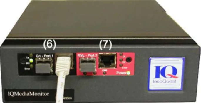
Figure 5 Front of IQMediaMonitor Chassis
The following list describes each of the numbered items on the front and back panels of the IQMediaMonitor Unit.
1. DC Power Input connection. Connect the IneoQuest 24V power supply to this port on the back of the IQMediaMonitor unit.
2. Chassis System Management Port network connection. Connect a standard 10/100 Base-Tx Ethernet cable to the port on the back of the unit. Use this port to connect the
IQMediaMonitor unit to your network for communication with IQMediaMonitor or another SNMP application running on the host workstation. Be sure to set an appropriate IP configuration for this port before connecting to your network.
3. DC power On/Off and On-reset switch. Main power (AC) disconnect is accomplished by unplugging the power cord from the AC outlet.
4. Chassis Serial port. 9-pin D-subminiature serial port on the back of the unit. Use this port to connect to a host computer. This connection is required when assigning an IP address to the chassis during the first use. For proper operation, use the null modem cable that came with your IQMediaMonitor. Serial communications settings are as follows: Bits per second: 9600, Data bits: 8, Parity: None, Stop bits: 1, Flow control: None.
5. ASI-Port, BNC video port. The port can be used with video analysis equipment or video decoder and monitor.
6. Standard Device Under Test (DUT) Port 1. Used to connect IQMediaMonitor to the DUT. Either a fiber cable to the Small Form-factor Pluggable (SFP) module or a copper CAT5 cable to the 10/100/1000 RJ45 connector can be used. The default configuration of this port is ARP disabled.
7. RVL Port 2. Used when the IQMediaMonitor is connected in line and passes through the Tx and Rx data with optional filtering or is configured as a Remote Video Link (RVL) port. Either a fiber cable to the Small Form-factor Pluggable (SFP) module or a copper CAT5 cable to the 10/100/1000 RJ45 connector can be used.
A cable clamp is included on the rear panel that can be used to secure the DC power cord in place. To install cable, remove screw, washers and clamp. Install clamp around DC power cable and install as shown in Figure 6.
Note: If the DC power cable clamp is used, be sure to install clamp as shown in Figure
4. Installing the clamp too close to the barrel jack could impart excessive stress
on the connector and cause damage.
Figure 6 DC Power Cable Clamp
5.3 System Start-up
This section will describe how to set the System Management Port IP configuration and prepare the system for monitoring and analysis functions.
Quick Start:
1. Setup the System Management Port IP Configuration as described in section 5.3.1. 2. Connect test port(s) as needed. Port 1 on the front is needed for all testing. Port 2 on
the front is used for tap, forwarding, packet remap (PacketMorph) and Remote Video Link (RVL) functions. The ASI port on the back is used to output selected IP streams as ASI transport streams.
3. Install application software on the host computer as described in the application user's guide.
4. Configure system for testing using IQController application or a web browser if using IQMediaAnalyser or IQMediaMonitor applications. Refer to the IQController application user's manuals or the Configuration via Web (HTML) Pages section for detailed information.
5.3.1 System Management Port IP Configuration
The System Management Port IP configuration is set at the factory for system test and burn in. The IP address set at the factory is taken from a revolving list and is not a single standard value so the address will usually vary unit to unit but two or more units may have the same address. If the factory setting can be used on your network the System Management Port can be used to change IP configuration of that port, otherwise a serial connection is needed. The IP configuration of the System Management Port can be changed using any of the following methods:
5.3.2 Configure Using a Network Connection with a Web Browser
Be sure the current IP configuration of the System Management Port will work on your network without conflict before continuing. Factory test and burn in settings were shipped with your system.
1. Verify the DC power switch is in the Off (down) position.
2. Connect power cabling and network connection to the back of the system. 3. Switch DC power switch to the On (center) position.
4. Use a web browser application on a host computer and enter the IP address of the IQMediaMonitor System Management Port to establish communications with the system.
5. Select the System IP Config link below the System Configuration heading from the list in the left hand side and configure settings as needed.
6. Once configuration is complete, select the Save Config link from the left hand side of the browser. Select Save & Reset and press the Save Config button for the settings to be operational after the system resets.
5.3.3 Configure Using a Network Connection with a Telnet application
Be sure the current IP configuration of the System Management Port will work on your network before continuing. Factory test and burn in settings were shipped with your system.
1. Verify the DC power switch is in the Off (down) position.
2. Connect power cabling and network connection to the back of the system. 3. Switch DC power switch to the On (center) position.
4. Use a telnet application on a host computer to establish communications with the Test System.
5. Type the ".shell" command and carriage return to list the current configuration of the System Management Port.
6. Type the "shell" command and carriage return to increment thru each setting and change any settings that are needed using carriage returns to continue.
7. End Telnet session when finished
8. Reset or power cycle the test system for new settings to be operational.
5.3.3.1 Configure Using a Serial Connection with a Serial Terminal application
Be sure to use the null modem serial cable that was shipped with your system. Serial communication settings are as follows: Bits per second: 9600, Data bits: 8, Parity: None, Stop bits: 1, Flow control: None.
1. Verify the DC power switch is in the Off (down) position. 2. Connect power cabling and serial cable to the back of the system.
3. Connect the other end of the serial cable to the serial port of the host computer that will be used.
4. Start the Serial Terminal (such as HyperTerminal) application on the host and configure settings as listed above.
5. Switch the test system DC power switch to the On (center) position.
6. Verify start up text scrolling in terminal window and wait for system prompt characters with ">".
7. Type the ".shell" command and carriage return to list the current configuration of the System Management Port.
8. Type the "shell" command and carriage return to increment thru each setting and change any settings that are needed using carriage returns to continue.
9. End terminal application session when finished.
10. Reset or power cycle the test system for new settings to be operational.
5.4 Specifications - IQMediaMonitor Series M1
5.4.1 Power and Cooling
Table A- 7 Power and Cooling
Description Specification Power Requirements -
External Power Supply
Mains Supply:
100 to 240VAC, 1.5A, 50 to 60Hz, voltage fluctuations up to +/- 10% of the nominal voltage.
The power supply contains no user serviceable parts an must not be disassembled.
Description Specification Power Requirements -
IQMediaMonitor Input 24VDC, 0.7A Typical
IQMediaMonitor Fans 2 internal cooling fans draw air in the right side of the enclosure and out the left side. A minimum of 2" (51mm) of clearance should be maintained on right and left sides for proper cooling.
5.4.2 Reference Clock and Calibration
Table A- 8 Reference Clock and Calibration Description Specification Internal Reference Clock 100 MHz +/- 50ppm accuracy
Calibration The IQMediaMonitor requires no periodic calibration adjustments during its lifetime.
5.4.3 Environmental
Table A- 9 Environmental
Description Specification Operating Temperature 0 to 40°C
Storage Temperature -20 to 60°C
Environment Indoor use only in a non-explosive atmosphere.
Pollution degree 2 Operating Altitude 2000m maximum
Operating Humidity 80% maximum for temperatures of to 310 C,
decreasing linearly to 50%relative humidity at 400C.
5.4.4 Regulatory
Information
Table A- 10 Regulatory Information
Category Standard or Description
EC Declaration of
Conformity - EMC Complies with the following: EMC Emissions
EN 55022 : 1994/A1 : 1995/A2 : 1997 Class A ITE emissions requirements (EU) EMC Immunity
EN 61326 : 1998 Electrical equipment for measurement, control and laboratory use - General Use
EC Declaration of
Conformity -Low Voltage
Complies with the Following:
EN 61010-1 : 2001 Safety requirements for electrical equipment for measurement, control and laboratory use
FCC Complies with the Following:
FCC 47 CFR Part 15 Class A emissions requirements
Product Safety CSA Listed file # 230516 Complies with the following:
UL Std No. 61010-1, 2nd edition – Safety
Requirements for Electrical Equipment for Measurement, Control and Laboratory Use, Part 1: General Requirements
CAN/CSA C22.2 No. 61010-1-04 – Safety Requirements for Electrical Equipment for Measurement, Control and Laboratory Use, Part 1: General Requirements.
Laser Safety The IQMediaMonitor employs a Class 1 laser device that complies with CDRH 21 CFR 1040.10 and 1040.11 and the IEC 825-1.
Note: To ensure compliance with the listed standards, any communication cables (other
than fiber optic cables) connected to this equipment should be well shielded with
low impedance connections to a conductive housing at each end.
5.4.5 Relevant Standards Compliance
Table A- 11 Relevant Standards Compliance IEEE 802.3-2002, IEEE Standard for Information
technology--Telecommunications and information exchange between systems--Local and metropolitan area networks--Specific requirements--Part 3: Carrier Sense Multiple Access with Collision Detection (CSMA/CD) Access Method and Physical Layer Specifications.
Small Form-factor Pluggable (SFP) Transceiver MultiSource Agreement (MSA), September 14, 2000.
IGMP v2 Internet Group Management Protocol, Version 2. RFC 2236, November 1997.
Information technology--Generic coding of moving pictures and associated audio information Systems, ISO/IEC 13818-1:2000(E)
One-way Loss Pattern Sample Metrics, RFC 3357.
RTP: A Transport Protocol for Real-Time Applications, RFC 3550.
Candidate Standard Amendment No. 1 to ATSC Digital Television Standard, Doc. A/53C (AVC/H.264 Version).
The BSD Syslog Protocol, RFC 3164.
5.4.6 IneoQuest Part Numbers
Table A- 12 IneoQuest Part Numbers IneoQuest Part Number Description
950-00001-001 Power Supply
870-00016-001 Power Cord, North America 870-00016-002 Power Cord, UK
870-00016-003 Power Cord, Europe 870-00016-004 Power Cord, Israel 870-00016-005 Power Cord, Japan 870-00016-006 Power Cord, Swiss 870-00003-001 Serial Cable, 6' (1.83m) 350-00002-002
- or -
350-00002-003
Fiber Optic Transceiver, SFP, LC 1000Base-SX
5.5 Cleaning - IQMediaMonitor Series M1
External surfaces may be cleaned using a clean cloth dampened with water or 70% isopropyl alcohol.
6 Configuration via Web (HTML) Pages
Many configuration settings are stored within the Singulus and IQMediaMonitor test
systems. Storing configuration settings in the test system allows the system to list streams and report alarms consistently to many monitoring applications, such as IQMediaMonitor
running simultaneously at different locations.
The test systems use a Hypertext Transfer Protocol (HTTP) web browser interface for basic system status, configuration management, setting alarm thresholds and account
management. Overall control and transfer of detailed information is accomplished using Simple Network Management Protocol (SNMP). The SNMP Management Information Base (MIB), and other details are explained in SNMP Communications section.
The web browser configuration interface is user privilege and password protected, with two levels; administrative and user. Administrative privileges give the user full access to all configuration parameters, while User privileges give the user access to a subset of the configuration parameters. Firmware updates can only be done in Administrative privileges, for example. The IQSoftwareSuite applications do not support privileges. For this reason, most configuration parameters are done within the web browser interface.
6.1 Accessing unit with a Web Browser
The status and management connection to the target is accomplished via an HTTP web browser. Simply enter the IP address of the system in an HTTP web browser and connect. A password window will appear as shown in Figure 7.
Figure 7 Network Password Window
Enter an appropriate user defined case-sensitive User Name and Password and click on the OK button. If a user defined password is not yet configured then use the default
Default administrator User Name: Admin
Default administrator Password: Su
The target will serve up Hypertext Markup Language (HTML) pages enabling basic status and management functions. Additional output data is obtained and control functions are done using IQMediaStimulus, IQMediaAnalyzer, IQMediaMonitor or another SNMP interface program.
By default, the Singulus will initially start-up in a mode of operation for use with IQMediaAnalyzer software. To change between operating modes, select the
Mode=IQMediaAnalyzer hyperlink at the top of the left browser window. At the system mode page, select either IQMediaStimulus or IQController to change operational mode and reset the system. The user is prompted for a valid Administrative username and password prior to the system successfully changing modes.
Figure 8 Singulus G1-T Operational Mode HTML Page
To switch the Singulus modes between IQMediaAnalyzer, IQMediaStimulus and IQController application modes, select corresponding hypertext. This will change modes and reset the Singulus. Allow the Singulus to reboot (this may take a few moments) then reconnect with the web browser or select the refresh button if the browser is still open. IQMediaMonitor M1 test systems do not support multiple operational modes and do not include the HTML page to switch modes. A password window will appear if you reconnected with a new browser session.
1) The target system chassis network port (management port) located on the
back panel must be connected to a network accessible by the client computer.
2) The target system must be properly connected, powered up and configured
with a valid network address. The initial IP address can be setup using the
serial interface of the target system located on the back panel.
6.2 Configuring the Unit with the Web Browser
The web browser interface allows the user to configure the unit and also, if the unit is in IQMediaStimulus mode, generate a stimulus. The browser interface is divided into several sections. A brief overview is given here, but more detailed decription is provided in the ‘Network Monitoring and Analysis Systems Web Page Interface User’s Guide for Singulus G1-T and IQMediaMonitor M1’, which is located on the IneoQuest web site.
6.2.1 System Status
The system status page, Figure 9, lists the current configuration settings and port status of the monitoring system. Use appropriate configuration pages to change settings. This page includes several sections; System Status, SNMP Configuration, Port Configurations, and Global Parameter settings.
Figure 9 System Status HTML Page
6.2.2 Network Statistics Pages
The network statistics section includes HTML page links for viewing per port statistics for RMON and IP TOS, an overview of the currently detected media streams, multicast testing statistics, and the historical alarm log.
6.2.3 System
Configuration Pages
The system configuration pages allow the user to set and update the system management port IP configurations, system data and time, front data port IP configurations and packet morph configuration. After any fields are changed, use the Save&Reset System button to update located on the ‘Save Config’ page and reset the test system for changes to take effect.
Note: Remember, if the system IP address is changed you must change IP address in
your browser to reconnect.
6.2.4 Monitor
Configuration Pages
The Monitor Configuration pages allow the user to configure global parameters and alarms, multicast scan mode and parameters, and the ASI output port scan parameters. Global parameters are IQMediaAnalyzer/Monitor specific and affect the overall behavior stream acquisition. Global alarms parameters are those that effect unit level alarms. In the multicast configuration page, the IGMP mode (autoscan, manual or disabled) and stream join/leave characteristics. The ASI configuration pages control the characteristics of the rear panel ASI output stream.
6.2.5 Media Configuration Pages
The Media Configuration pages allow the user to configure IP Flow aliases, recognition characteristics, and alarm templates for both video and voice flows. Alias files can be either manually generated through these browser pages or downloaded into the unit via the ‘Download Configuration’ browser page. Using either method requires a ‘System Save and Reset’ for the settings to be saved after a power cycle.
6.2.6 Configuration Management Pages
The Configuration Management pages allow the user download new firmware releases into the unit, download and upload configuration files, save to FLASH the running configuration and reset the unit.
6.2.7 Account Management Pages
The Account Management pages allow the user to download or examine unit’s existing license status and set up user accounts.
6.2.8 Factory Management Pages
The Factory Management pages allow the user to view the current hardware level settings of the unit, such as original unit manufacture date, current firmware revision, unit and hardware component level serial numbers and a listing of the FLASH file system. The user also has the ability to upload the displayed information to a text file.
7 SNMP Communications
System configuration and alarm threshold settings can all be set with HTML pages as described in the previous chapter. Operational monitoring is done using IQMediaMonitor or another Simple Network Management Protocol (SNMP) management tool. The detailed statistics and performance data describing the network traffic can be gathered using an SNMP management tool.
The IneoQuest IQMediaMonitor application can be used as the SNMP interface to setup single or test systems for network monitoring. Details describing the setup and operation the IQMediaMonitor application are included in a separate IQMediaMonitor application User's Manual.
For users familiar with or requiring the use of an SNMP tool other than IQMediaMonitor, the latest Management Information Base (MIB) is available from IneoQuest Technologies. A few basic notes regarding SNMP and the MIB:
• The default Get Community Name is public. This is a user-defined name. Refer to the SNMP configuration HTML page section of this chapter for details.
• The default Set Community Name is private. This is a user-defined name. Refer to the SNMP configuration HTML page section of this chapter for details.
• The Media Delivery Index (MDI) is displayed in microseconds.
• The network utilization and but rate thresholds are in percentages scaled up by 100. For example: a network utilization of 10 means 0.10%; the min. bit rate threshold of 2500 means generate an alarm if the stream bitrate goes 25% below the current bitrate.
• Users can change thresholds to their needs at runtime using SNMP. All the thresholds are in the Media Status Table.
• Users can clear the alarmlog using the SNMP MIB command clearLogTable in ioqFmAlmLog branch.
8 IQFirmware and IQSoftwareSuite Updates
The Singulus G1-T and IQMediaMonitor M1 operate using both firmware stored in the physical unit and application software executing on a PC connected via a management port to the unit. When upgrading a unit, both the firmware and IQSoftwareSuite applications should be downloaded to ensure there are no incompatibilities between the releases. There are two methods of updating the firmware in the Singulus G1-T and the
IQMediaMonitor M1; using the IQFirmwareUpdate application and via the web browser. Firmware prior of release 1.1a must be upgraded using the IQFirmwareUpdate application. IQFirmwareUpgrade is obsolete and not to be used on firmware releases after release 1.1a. The web browser method of upgrading firmware must be used.
Updated firmware files are available on the IneoQuest web site or FTP site listed below and must be downloaded to a local drive prior to running the IQFirmwareUpdate application or the web browser.
IneoQuest web site URL: http://www.ineoquest.com IneoQuest FTP Server: ftp.ineoquest.com
8.1 Upgrading a unit using IQFirmwareUpdate
The IQFirmwareUpdate application connects the host computer with the chassis via the chassis network port. The host and the Singulus must both be connected to a network that will allow a link between the two. Once the network link is established within the
IQFirmwareUpdate application, firmware can be remotely updated and the Singulus rebooted.
Note: If this application is not available please download the latest software from the
IneoQuest website.
Earlier versions of IQController contained a similar Update Firmware...
function within the IQController window.
The following steps outline how to update the firmware on the Singulus using the IQFirmwareUpdate application (Version 2.1.D and later).
• Download the intended firmware version file (.iqz file extension) to the host computer. The firmware is available from the Downloads area of the IneoQuest web site or from the IneoQuest FTP site.
• Start the IQFirmwareUpdate application. By default this application should be installed in an "IneoQuest" folder in the Windows Start menu, see Figure 10.
Figure 10 Start IQFirmwareUpdate Application
• The IneoQuest Firmware Update Application window will open. Click on the "Browse" button to find and select the downloaded firmware file then click on the Open button, see Figure 11.
Figure 11 Select firmware file
• The versions of all the files contained in the .iqz file will be displayed in the Update Firmware, Host Version section of this window, see Figure 12.
Figure 12 Host Versions
Input the IP address of the chassis to be updated into the Target Definition, IP Address location (also input the port if defined differently). Click on the Connect button. This will connect the IQFirmwareUpdate host application with the target chassis and compare the host file versions with the target file versions, see Figure 13.
.
• Files now shown with a green diamond have the same or newer versions on the target. Files shown with a red diamond have older versions on the target. Files in Figure 13 show all file versions match. Files can be updated (overwritten) even if they match.
• Click the Update All Files button to update all files in the connected chassis or select one or more files (also use CTRL+left mouse to select several or shift+left mouse for a group select) then click on the Update Selected button, as shown in Figure 14.
Figure 14 Select Files to Update
• After selecting the update button the target reboots into maintenance mode and the files get updated.
Figure 15 Updating Files
• The chassis reboots to show the updated files.
• The Reset Target button can be used with or without file updates to reset the connected chassis.
• Select disconnect to complete the process. The chassis will reboot when disconnect is selected or if the Firmware Update window is closed. Allow sufficient time for the chassis to reboot before connecting again with any application.
8.2 Upgrading a Unit Using the Web Browser
Firmware versions later than 1.0a support firmware upgrades using the web browser. The following steps outline how to update the firmware on the Singulus G1-T or IQMediaMonitor M1 using the web browser.
• Download the intended firmware version file (.iqz file extension) to the host computer. The firmware is available from the Downloads area of the IneoQuest web site or from the IneoQuest FTP site.
• Connect to the unit using the web browser by using the management IP address previously assigned to the unit.
• Select ‘Download Firmware’ from the menu at the left side of the browser page, under the Configuration Management pages section.
• At the ‘Browse’ button, navigate to the location of the firmware to be installed. The file will be a TB-XXXX.XX.iqz file for the Singulus G1-T or a MA-XXXX.XX.iqz for an IQMediaMonitor M1.
• After the file has been selected, press ‘OK’, then press the ‘Download Firmware’ button to download the file into RAM on the target.
• The unit will proceed to download the file into RAM on the target system. After the status message, ‘Firmware downloaded and Validated’, press the ‘Update Firmware’ button. The target will sequence through a series of status messages as it removes the previous version and decompresses the new version. When the update is complete, the target will indicate that it is rebooting and the user should wait 30 seconds before continuing.
• After the firmware update is complete and the target comes out of reset, it will be operating in IQMediaAnalyzer mode. It can optionally be reconfigured forIQMediaStimulus or IQController mode via the Operating mode browser page.