Design
of
a High-speed Optical Interconnect for Scalable Shared Memory
Multiprocessors
Avinash Karanth Kodi and Ahmed Louri Department of Electrical and Computer Engineering
University of Arizona Tucson, A Z - 85721, USA E-mail:louri @ece.arizona.edu
Abstract
This paper proposes a highly connected optical inter- connect based architecture that maximizes the channel availabilifyforfuture scalable parallel computers such as Distributed Shared Memory (DSM) multiprocessors and cluster networks. As the system size increases, various messages (requests, responses and acknowledgments) in- crease in the network resulting in contention. This results in increasing the remote memory access latency and sig- nificantly affects the peformance of these parallel com- puters. As a solution, we propose an architecture called RAPID (Recon$gurable and scalable All-Photonic Inter- connect for Distributed-shared memory), that provides low remote memory access latency by providing fust and efi- cient unicast, multicast and broadcast capabilities using a combination of aggressively designed WDM, TDM and
SDM
techniques. We evaluated RAPID based on network characteristics and by simulation using synthetic traffic workloads and compared it against other networks such as electrical ring, torus, mesh and hypercube networks. We found that RAPID outpeijorms all networks and satisfies most of the requirements of parallel computer design such as low latency, high bandwidth, high connectivity. and easy scalability.1 Introduction
Large-scale distributed shared-memory (DSM) ar-
chitectures provide a shared address space supported by physically distributing the memory among different processors[l, 21. The key strength of DSM systems is that communication occurs implicitly as a result of con- ventional memory access instruction (i.e. loads and stores) which makes them easier to program. One of the funda- mental communication problem in DSM systems that sig- nificantly affects scalability, is the increase in remote mem- ory access latency
as
the number of processors increase in the system. Latency redncing[3] techniques and latencyhiding techniques[l,
2,
31 are commonly used to toler- ate large remote latencies. However, these successful and efficient latency-tolerating techniques require much more bandwidth, and create much more memory traffic in the network. In addition, every transaction in a DSM system consists of 3 request, response (data) and several acknowl- edgment messages. As the system size increases, more processorsare
injecting more messages (both transaction related messages and latency tolerating requests) into the network that causes network contention[4] for various shared resources. Moreover, communication paradigms such as multicast and broadcast algorithms (essential for synchronization and to reduce hot spots) are generally more complex to implement and expensive (in terms of la- tency) using electrical interconnects.One technology that has the potential
for
providing higher bandwidths and lower latencies at lower power re- quirements than current electronic-based interconnects is optical interconnects[5,6]. The use of optics has been rec- ognized widelyas a solution to overcome many fundamen- tal problems in high-speed and parallel data communica- tions. This paper proposes an integrated solution to solve the remote memory access latency in DSMs and still be able to scale the network significantly using low-latency, high-bandwidth optical technology. The proposed archi- tecture, called RAPID dramatically reduces the critical re- mote memory latency in high-performance DSMs, ( I ) by increasing the connectivity and maximizing the channel availability,(2)
by using a decentralized media access pro- tocol and wavelength re-use schemes, and (3) by using pas- sive optical interconnects, thereby making the architecture cheaper and faster.2
Architecture Overview
In this section, we describe and explain the design of RAPID architecture. A RAPID network is defined by a 3-tuple:(D,G,C) where C is the total number
of
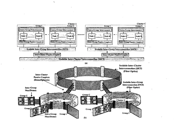
clusters,Figure 1. shows the RAPID network. Figure l(a) shows D nodes connected using Intra Group Interconnect, G groups connected using SlGl and C clusters connected using SIC1 interconnects.
Figure l(b) shows the conceptual diagram of RAPID network.
total number of nodes per group. Each node is identified as R(d,g,c) where 1 5 d 5 D 15 g 5 G; 1
I
c5 C such
that G5 D-1 and C
5 D. This condition enables every
group to communicate to every other grouplcluster.Figures I(a) and l(b) show the RAPID architecture. In fig.l(a) each node in RAPID network, contains the pro- cessor and its caches, a portion of the machines physi- cally distributed main memory, and a node controller. 1 up to
D
nodes are connected together to form a group. All nodes are connected to two suh-networks; a scalable Intra- Group interconnection (IGI) and a scalable Inter-Group Interconnection (SIGI) via the Inter-Group Passive Cou- plers (IGPC). SIC1 is further connected to the Scalable Inter-Cluster Interconnection (SKI) using the Inter-Cluster Passive Couplers to increase the scalability of the archi- 'tecture. We have separated intra-group (local) and inter- grouplinter-cluster (remote) communications from one an- other in order to provide a more efficient implementation for both communications. Figure I(b) shows the concep- tual diagram of RAPID network.Figure 2 shows the functional diagram of RAPID. As seen, the figure shows D
=
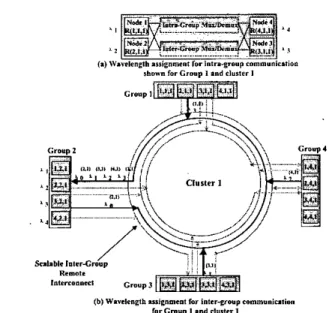
4 (nodes), G = 4 (groups) and C = 1 (cluster). Within a group, all nodes are con- nected to multiplexers and demultiplexers for intra- and inter-grouplinter-cluster communication. We will use thissystem to discuss the wavelength allocation, message rout- ing for both local and remote communication and, the de- sign of RAPID to support multicast and broadcast commu- nications.
Wavelength Assignment a n d Routing for Group Com- munication: We propose an efficient wavelength assign- ment strategy based on wavelength re-use and spatial di- vision multiplexing (SDM) techniques[lOl. The proposed methodology allows wavelengths to be re-used when they are spatially separated, that is, when they are used at the
lo-
cal (intra-group)level, remote (inter-group) level or remote (inter-cluster) level. The number of wavelengths'employed for intra-group communication equals the maximum num- ber of nodes, D located in each group of the system. Figure 2(a) shows an example of the intra-group wavelength as- signment and shows group 1 of cluster 1. The wavelengths located next to each node correspond to the wavelength that each node receives on. This same wavelength assign- ment applies to all groups in the system i.e. R(l,g,c) will always receive on XI for intra-group communication. For example, for node R ( I , I , l ) to transmit to node R(3,IJ) in group 1, node R( I ,I ,
I)
would simply transmit on the wave- length assigned to node R(3,l,l) (e.g. Az). Therefore, dis- tinct wavelength allocation in different groups is possible by assigning an unique wavelength to every node at which.
Remalr,ntrmanort c,o"p,
(b) Wavelength ulivmemt for i n t e r y o u p c o r n m ~ ~ i ~ i i o m
rorcnvp I ."dCl".,"l
Figure 2. Wavelength assignment for intra- and inter-group communication.
it can receive optical packet from other intra-group nodes. For the remote wavelength assignment scheme, we study two cases: (1) a single cluster configuration R(d,g,l) and (2) multi-cluster configuration R(d,g,c). In our remote wavelength assignment scheme shown in Figure 2(b) for R(d,g,l), the objective here is to selectively merge dif- ferent wavelengths from various groups to provide high connectivity and at the same time to maximize the chan- nel utilization. All nodes within the source
group
areas-
signed a unique wavelength at which the nodes can trans- mit to communicate with any destination group. At the destination group, each node receives optical signals at a unique wavelength as shown by the wavelength located next to each node in Figure 2(b) for group 2. Remote wave- lengths are indicated by
Ayk),
where i is the wavelength, j is the group number and k is the cluster number from which the wavelength originates. In Figure 2(b), any node ingroup
3 can communicate with group 2 on Ay"), any node in group 4 can communicate with group 2 on A?,') and any node in group 1 can communicate with group.2 on A y " ) . For clarity, only the wavelengths received by group 2 are shown in bold in fig 2(b). Note here that, the wavelength Af") is the wavelength at whichgroup 2 com- municates with itself. This wavelength is used to multicast transaction requests to all nodes within a group. Now, the multipl&xed signal received by group 2 is demultiplexed and node R(1,2,1) receives signals on wavelengthAy'),
node R(2,2,1) receives signals on wavelength A?"), node R(3,2,1) receives signals on wavelength A y " ) and the sig-nal on wavelength Af") is broadcast to every node within group
2.
For remote traffic, the number of wavelengths required to obtain the connectivity mentioned above, is G i.e. (G - 1) wavelengths are required to communicate with every other group and I wavelength for multicast commu- nication. This givesus
the criteria, that the there should exist at leastG
- 1 nodes within a group to receive data from other groups. The maximum number of wavelengths then required for either intra-group or remote inter-group communication for R(d,g,l) configuration is, simplyD.
This represents an order of magnitude reduction in the to- tal number of wavelengths required compared to a straight forward wavelength.assignment where each group is
asso-
ciated with a distinct wavelength.Remote inter-group communication takes place when both the source and destination nodes are
on
differentR ( z ,
g, 1) can transmit the packet on a specific wavelength to grouph.
The destination node in grouph
which can receive the packet from group g may not b e node y (the in- tended destination). To illustrate this, consider Figure 2(b). Let the source node be R(l,3,1) (group 3) and the desti- nation node be R(3,2,1) (group 2). The source node can transmit to group 2 on wavelength Ay"). The destination node which receives packets for remote communication in group 2 on wavelengthA y " )
is R(1,2,1). Node R(I.2,l) then uses the intra-group interconnection to forward the packet to node R(3,2,1) on wavelength As. In some cases, source node R(x,g,l) may directly transmit to destination node R(y,h,l). As in the previous example, if the destina- tion was node R(1,2,1), then node R(1,3,1) could directly transmit onA?')
which is received by node R(1,2,1), the intended destination.Wavelength Assignment a n d Routing for Inter-Cluster Communication: Inter-cluster communication for con- figuration R(d,g,c), we extend the basic configuration of R(d,g,l) shown in Figure 2(b) by replacing group 4 and connecting cluster 1 to SIC1 using low loss passive bi- directional demultiplexers as shown in Figure 3. For inter- cluster communication, different wavelengths from differ- ent clusters are selectively merged and and dropped at ev- ery cluster by demultiplexing the signals propagating on the S K I . Remote inter-cluster communication takes place when both the source and destination nodes are on differ- lustrate this, consider that the source node is R(2,3,1) and the destination node is R(4,3,2). Cluster 2 is reachable by group 1 within cluster 1 by using the same wavelength as- signment
as
explained above. Node R(2,3,1) transmits on wavelength A?') and is received by the intermediate node l a shown by R(2,1,1). In order to communicate to clus- ter 2, node R(2,1,1) transmits on wavelength A y " ) , This groups, R(x,g,l),,,,,,#
R(y,h,l)d,,tin,tion. Now, nodelntrrrnrdialc Node Is
,
Figure 3. Scalable Inter-Cluster Interconnection.path is shown by the hold dotted lines to indicate the trans- mission from group 1 in cluster 1 to group 3 in cluster 2. Note, that the signals from cluster 1 is first demnltiplexed and merged with SIC1 selectively such that different wave- lengths are multiplexed to different fibers. At cluster I , the multiplexed signals are again demultiplexed, and wave- length Ay") is received by intermediate node Ib R(1,3,2) as shown in Figure 3. In order to reach the intended des- tination R(4,3,2), node R(1,3,2) transmits using the intra- group interconnection on wavelength Xq. The maximum diameter of R(d,g,c) is 4. From the previous
example,
if the intended destination was located in a group other than group 3, then it would require an additional hop. The con- figuration R(d,g,c) trade-offs wavelength usage to latency for smaller system sizes. For example, by using 4 wave- lengths and passive optical components, R(d,g,c) can ac- commodate 64 nodes, where as in R(d,g,l) configuration, to design a network with 64 nodes, 16 wavelengths are re- quired. With 16 wavelengths, R(d,g,c) has the potential to scale to as many as 4096 nodes. However, R(d,g,l) has a lower latency due to lower diameter than the R(d,g,c) con- figuration.Time division multiple access (TDMA) protocol is used as a control mechanism.to achieve mutual exclu- sive access to the shared local and remote communica-
tion channels[7,
81.
In this paper, we consider an optical token based TDMA protocol with pre-allocation to pre- vent collision of requests by different processors. A novel media access protocol is discussed for RAPID so as to minimize the remote access latency. The optical tokens generated for inter-grouplinter-cluster communications are shared among the nodes locally connected and not among all nodes. This is a significant feature of the proposed network, as the queuing time to transmit the packets re- duces considerably. In RAPID, under worst case scenario,a
node waits only forD
- 1 transmissionsof
the packet to a particular remote destination grouplcluster before it can transmit its request, thereby significantly reducing the remote group latency. We generate two sets of token for every intra-group g; one set of D tokens are shared for inter-grouplinter-cluster communications and the other set of (G5 D)
tokens are shared.for inter-group communica- tions. These local and global token are shared by the intra- group nodes connected to the concerned group i.e. R(g). In order to prevent collision of requests, a processor can trans- mit an address request, response or an acknowledgement to another processor (localiremote) depending on the to- ken received. The implementation details of RAPID have been published elsewhere[9].I W Bo €4 40 1 0 0 100 2w 3w Iw 9 0 WO Number of Processors (e)
& M e s h &TO,U* --Hypercube +SOCN --tClassical Ring - c W l D ( d . g . l ) t RaPID(d.g.c) -Crossbar
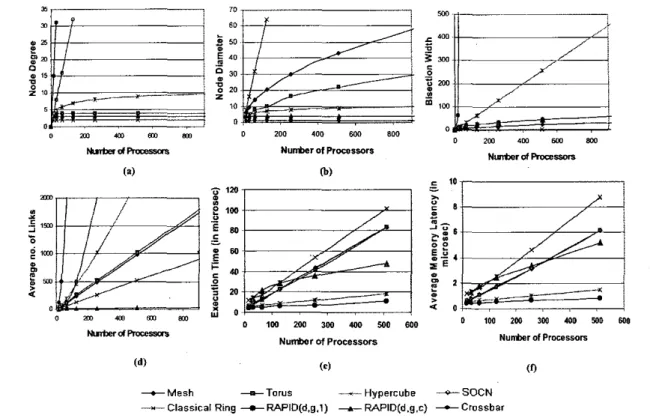
Figure 4. Fig (a) shows the degree comparison, (b) shows the diameter comparison, (c) shows
the bisection width comparison for varying number of processors, (d) shows the no.
of
linkscomparison,
(e)
shows the execution time for various topologies simulated and (f) shows theaverage remote memory access latency for various topologies.
3 Performance
Analysis
In this section, we evaluate the performance of RAPID for DSMs by analyzing the network characteristics and performance based on simulation. For clarity, only RAPID R(d,g,c) configuration is compared to several well-known network topologies such as a traditional crossbar net- work (CB), the Binary
Hypercube,
the
Ring network, the Toms, 2-D Mesh and Scalable Optical Crossbar Network (SOCN)[ IO] as shown in Figures 4(a-d). Each of these net- works are compared with respect to degree, diameter, num- ber of links and bisection width. RAPID network main- tains a constant degree for any system size as each node is connected to only intra- and inter-grouplcluster inter- connectsas
seen in Figure 4(a). RAPID supports better connectivity at a reasonable cost a s the comparison of the diameter is seen in Figure 4(b). The bisection width of RAPID network is very comparable to the best of the scal- able networks as seen in Figure 4(c). RAPID shows theleast cost for inter-cluster communication, thereby show- ing a much better scalability
in
the number of links for very large-scale systems as seen in Figure 4(d).Simulation Assumptions and Methodology In this sec- tion, we describe the simulation methodology and the preliminary results obtained by comparing both R(d,g,l) and R(d,g,c) with few scalable electrical networks such as the 2-D Mesh, 2-D Torus, Hypercube and the classical ring. We use CSIM[ll], a process-oriented, discrete-event model simulator to evaluate the performance OF RAPID network using synthetic traffic workloads. Due to the com- plexities of
a
full system simulation and the difficulty in tuning the simulator for large number of nodes, we cur- rently present data for as many as 512 nodes. For the electrical network, wormhole routing is modelled with a flit size of 8 bytes and up to 4 virtual channels per link. Various routing, switching and propagation times[ 121 are chosen such that they reflect future high performance elec- trical interconnect technology. For the optical network, weassume a channel speed of I O Ghz, based on current optical technology. We model
O/E
(optical to electrical) and WO (electrical to optical) for both configurations. In this simu- lation, we model accurately contention at all resources for both electrical and optical networks, and is not presented here due to page constraints[9].Simulation Results: We evaluated RAPID network with other electrical topologies such as the classical ring, the hypercube, the 2-D mesh and the 2-D torus based on execu- tion time and average remote memory latency: Figure 4(e) shows the execution time for varying number of proces- sors for both the simulated electrical and optical networks. RAPID R(d,g,l) outperforms all networks by maximizing the the channel availability and maintaining a low diame- ter for large number of processors. RAPID R(d,g,l) out- performs the classical ring by almost 89% for 512 nodes. The mesh and torus have’ similar latencies, with R(d,g,l) configuration outperforming them by almost 86% for 512 nodes. The hypercube .performs reasonably well, though R(d,g, I ) outperforms hypercube by almost 38%. R(d,g,c) actually has a higher latency than most networks for small system configurations. But, as the system size increases, the curve for R(d,g,c) starts to flatten showing a reason- able performance as the diameter doesn’t change with in- crease in number of processors. For system configurations greater than 512, we expect the latency for R(d,g,c) con- figuration to further stabilize and perform better than other networks. All electrical networks showed different laten- cies depending on how many switches needed to be tra- versed. Figure 4(f) shows the average remote memory ac- cess latency. RAPID R(d,g,l) performed the best a s com- pared to all other networks. RAPID R(d,g,l) outperformed hypercube by 46%, the mesh, torus by 87% and the classi- cal ring by 91%. These results show that RAPID R(d,g,l) can re.duce the latency for smaller system configurations by using more wavelengths and maintaining low diame- ter. Additionally, RAPID R(d,g,c) can scale to very large configurations, yet provide low latency by using minimal wavelengths.
4
Conclusion
In this paper, we proposed an optically interconnected architecture called RAPID to reduce the remote memory access latency in distributed shared memory multiproces- sors. RAPID was completely designed using passive op- tical technology making the proposed architecture much faster and inexpensive as compared to other optical and electrical architectures. RAPID, not only maximizes the channel availability for inter-group communication, but at the same time wavelengths are completely re-used for both intra-group and inter-group communications. This novel architecture fully utilizes the benefits of wavelength divi-
sion multiplexing along with space division multiplexing to produce a highly scalable, high bandwidth network with low overall latency that could be very cost effective to pro- duce.
Acknowledgement This research is sponsored by NSF grant no. CCR-0000518.
References
[I] J.Laudon and D.Lenoski, “Sgi origin: A ccnuma highly scal- able server:’ in Proceedings of the 24rh Annual lnremarional Symposium on Cornpurer Archirecrure, June 1997, pp. 241- 251.
121 David E. Culler, Jaswinder Pal Singh. and Anoop Gupta, Par- allel Cornpurer Archirecrure: A Hardware/Sofrware Approach.
Morgan Kaufmann, San Fransisco, 1999.
[3] Jose Duato. Sudhakar Yalmanchili. and Lionel Li. Inrercon- necrion Network: An Engineering Approach. IEEE Com- puter Society Press, New Jersey, 1997.
[4] Donglai Dai and Dhabaleswar K. Panda,. ”How much does network contention affect distributed shared memory perfor-’ mance:’ in lnremarional Conference on Parallel Processing (ICPP ‘97), 1997, pp. 454461.
[SI David A.B.Miller, “Rationale and challenges for optical in- terconnects to electronic chips,” Proceedings of the IEEE, vol. 88, pp. 728-749, June 2000.
[6] J.H. Collet, D. Litaize, 1. V. Campenhut, C. Jesshope, M. Desmulliez, H. Thienpont, 1. Goodman, and A. Louri, “Ar- chitectural approaches to the role of optics in mono and multi- processor machines,” Applied Optics. Special issue on Optics in Computing, vol. 39, pp. 671682,2000.
[7] Patrick Dowd; James Perreault, John Chu, David C. Hoffmeister, Ron Minnich, Dan Bums, Frank Hady, Y. 1. Chen, and M. Dagenais, ”Lighnting network and systems ar- chitecture,” Joumal of Lighrwave Technology, vol. 14. pp.
1371-1387, 1996.
[8] loon-Ho Ha and T.M.Pinkston, ‘The speed cache coherence for an optical multi-access interconnect architecture:’ in Pro- ceedings of rhe 2nd lnremarional Conference on Massively Parallel Processing Using Optical Inrerconnecrionr, 1995, pp. 98-107.
(91 Avinash Karanth Kodi and Ahmed Louri, ‘A scalable arcbi- tecture for distributed shared memory multiprocessors using optical interconnects:’ in ro appear in 18rh lnremarional Par- allel and Disrribured Pmcessing Symposium, April 2004. [IO] Brian Webb and Ahmed Louri, ” A class of highly scalable
optical crossbar-connected interconnection networks (socns) for parallel computing systems,” IEEE Transacrions on Par- allel and Disrribured Sysrems. vol. 11, no. 1, pp. 444458, May 2000.
[ I I ] Herb Schwetman, “Csiml9: A powerful tool for building system models,” in Proceedings of rhe 2001 Winrer Simularion Conference, 2001, pp. 25&255.
[I21 Mauael E. Acacio, Jose Gonzalez, Jose M. Garcia, and Jose Duato, ‘The use of prediction for accelerating upgrade misses in cc-numa multiprocessors,” in Pmceedings of the Inrem- rional Conference on Parallel Archirecrures and Compilarion Techniques, 2002, pp. 155-164.