ISSN: 2249-2615 http://www.internationaljournalssrg.org
Page 26
Analysis of Various Crosstalk Avoidance
Techniques in Optical Multistage Interconnection
Network
Sehajpal Kaur1, Rajan Vohra2, Sandeep Kaur2 Department of Electronics Technology
Guru Nanak Dev University Amritsar, Punjab, India
Abstract- This paper presents the various crosstalk avoidance algorithms in optical multistage interconnection network. The
major problem introduced by optical multistage
interconnection networks is crosstalk which is caused by the coupling of two signals within same switching element. To avoid a crosstalk, many approaches have been proposed such as time domain and space domain approaches. One way to solve this problem is to avoid coupling of two signals within same switching element. In this paper, various algorithms such as Window method, Improved Window method and Bitwise window method are implemented to avoid crosstalk. Window Method is used to find out which messages have conflict and it is also used to find the message that are not in same group because it causes crosstalk in the network. Then Improved window method is used in which first window is eliminated. Then Bitwise window method in which all the binary bits of single row in each window are converted to decimal so complexity is reduced.
Keywords- Optical Multistage Interconnection Networks,
Window Method, Improved window method, Bitwise Window Method, Crosstalk Algorithm.
I. INTRODUCTION
Interconnection Networks play a major role in the performance of modern parallel computers. Many aspects of interconnection networks, such as implementation complexity, routing algorithms, performance evaluation, and fault tolerance, have been the subject of research over the years. There are many factors that may affect the choice of appropriate interconnection network for the underlying parallel computing environment. Multistage interconnection networks (MINs) consist of more than one stages of small interconnection elements called switching elements and links interconnecting them. The number of stages and the connection patterns between stages determine the routing capability of the networks. MINs were initially proposed for telephone networks and later they are used in multiprocessing systems to provide
cost-effective, high-bandwidth communication between processors and/or memory modules. In electronic MINs electricity is used, where as in Optical MINs light is used to transmit the messages. This advantage makes the signal transmission in optical network faster. The electronic MINs and the optical MINs have many similarities, but there are some fundamental differences between them such as the optical-loss during switching and the crosstalk problem in the optical switches [1,2]. In electrical multistage interconnection network, in which optical signal is converted to/from electrical signal at the network input/output. Available optical MINs were built mainly on
banyan or its equivalent baseline and omega networks because they are fast in switch setting (self-routing) and also have a small number of switches between an input-output pair. There are two ways to solve crosstalk problem in Optical Networks:
1. Space Domain Approach 2. Time Domain Approach
With the time domain method, two connections will be launched at different times if they use the same SE. Whenever the limitation of the network size is reached, the time domain method may be used as a feasible way to trade the maximal bandwidth available to each particular input and output pair for enhanced connectivity. Second, it is useful when future technology let the transmission rate to expand faster than the network size or when the cost of expanding the bandwidth of each connection becomes as “cheap” as the cost of building a network of twice its original size. The crosstalk occurs when two signal channels interact with each other. When a crosstalk happens, a small fraction of the input signal power may be detected at another output although the main signal is injected at the right output. For this reason, when a signal passes many switching elements, the input signal will be distorted at the output due to the loss and crosstalk
ISSN: 2249-2615 http://www.internationaljournalssrg.org
Page 27
introduced on the path. This was not a big issue in electrical MINs, but because the more stringent bit error rate in optical network, it has become a big problem.In this paper, various algorithms such as Window method, Improved Window method and Bitwise window method are implemented to avoid crosstalk[9,10].
II. WINDOW METHOD
its corresponding destination address is combined to produce a combination matrix. The window is used in the combination matrix from left to right except first and last column. If two messages have the same bit pattern, they will cause conflict in the network. Hence, they must be routed in different passes[6]. To see how the WM works, refer to the following example. Consider the network Window Method is a technique used to find which messages should not be in the same group because they introduce crosstalk in the network. It can be described as, for network size N*N, there are N source and N destination address[7]. Each source and size is 8x8and permutation is shown in figure 4.5 Source Destination 000 101 001 001 010 011 011 110 100 000 101 010 110 100 111 111 Figure 1Permutation in binary format Using the window method shown in Figure 2, the window size is M-1=2 (M= log2 8=3) and the number of windows is M=3 (w0, w1, w2). message 000 &100 have conflict message 001 & 101 have conflict message 010 & 110 have conflict message 011 & 111 have conflict message 000 &110 have conflict message 001 & 101 have conflict message 010 & 100 have conflict message 011 & 111 have conflict message 000 &110 have conflict message001 &100 have conflict message 010 &101 have conflict message 011 &111 have conflict Figure 2 Optical window & Conflicts between different windows For the first row message 000 with 100, 101 with 110 have a conflict, so the value of these columns is assigned to 1 and the value of other columns is assigned to 0 because 000, 001, 010, 011, 101 and 111 do not have any conflict with 0. This function is a same for other rows[3,4]. After using a window method, the conflict matrix is generated at the output is shown Table I below
.
TABLE I Conflict Matrix for Window Method In the above table, 1 represents the conflict between message and 0 represents the message which do not have conflict. The flow chart of Algorithm are shown in figure 3. III. IMPROVD WINDOW METHOD The number of windows in WM is equal to the number of stages (M= log2 N, Where M is the number of stages). In Improved WM (IWM) to find the conflicts among the messages the comparison of the first window is eliminated. The number of windows are M-1(M is number of stages) after eliminating first window i.e the number of windows is only two because of eliminating the first window (w0).Messages 000,001,010 and 011 pass same switch with messages 100,101,110 and 111 respectively in the first stage. As a result the number of steps is reduced approximately by 1/M compared to WM. It takes less time Message 000 001 010 011 100 101 110 111 000 001 010 011 100 101 110 111 0 0 0 0 0 0 0 0 0 0 0 0 0 0 0 0 0 0 0 0 0 0 0 0 0 0 0 0 0 0 0 0 1 1 1 0 0 0 0 0 0 1 1 0 0 0 0 0 1 0 1 0 0 0 0 0 0 0 0 1 0 0 0 0 NoISSN: 2249-2615 http://www.internationaljournalssrg.org
Page 28
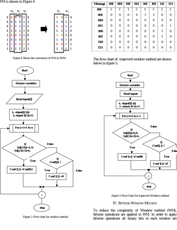
to find the conflicts than the windows method, so complexity is reduced further. The conversion of WM to IWM is shown in Figure 4
Figure 4Shows the conversion of WM to IWM
Figure 3Flow chart for window method
Table II
Conflict matrix for Window Improved Method
The flow chart of improved window method are shown below in figure 5.
Figure 5 Flow Chart for Improved Window method
IV. BITWISE WINDOW METHOD
To reduce the complexity of Window method (WM), bitwise operations are applied in WM. In order to apply bitwise operations all binary bits in each window are
Message 000 001 010 011 100 101 110 111 000 001 010 011 100 101 110 111 0 0 0 0 0 0 0 0 0 0 0 0 0 0 0 0 1 0 0 0 0 0 0 0 0 0 0 0 0 0 0 0 0 1 0 0 0 0 0 0 0 1 0 0 0 0 0 0 0 0 0 0 1 1 0 0 0 0 0 1 0 0 0 0 Read inputs False False If Conf[j i] ≠0
Start Declare variables t1 =input[i] [k] t2 =input [i] [k+1] If In[j][k]=t1& In[j] [k+1]=t2 Conf [i j] =Conflit c Conf [i j] =0 For j=i+1 to n-1 False stop False True Start Declare variables Read input[i] t1 =input[i] [k] t2 =input [i] [k+1] If In[j] [k]= t1 & In[j] [k+1]=t2 Conf [i j] =Conflict If Conf[ji] ≠0 c Conf [i j] =0 For j= i+1to n stop True True True
ISSN: 2249-2615 http://www.internationaljournalssrg.org
Page 29
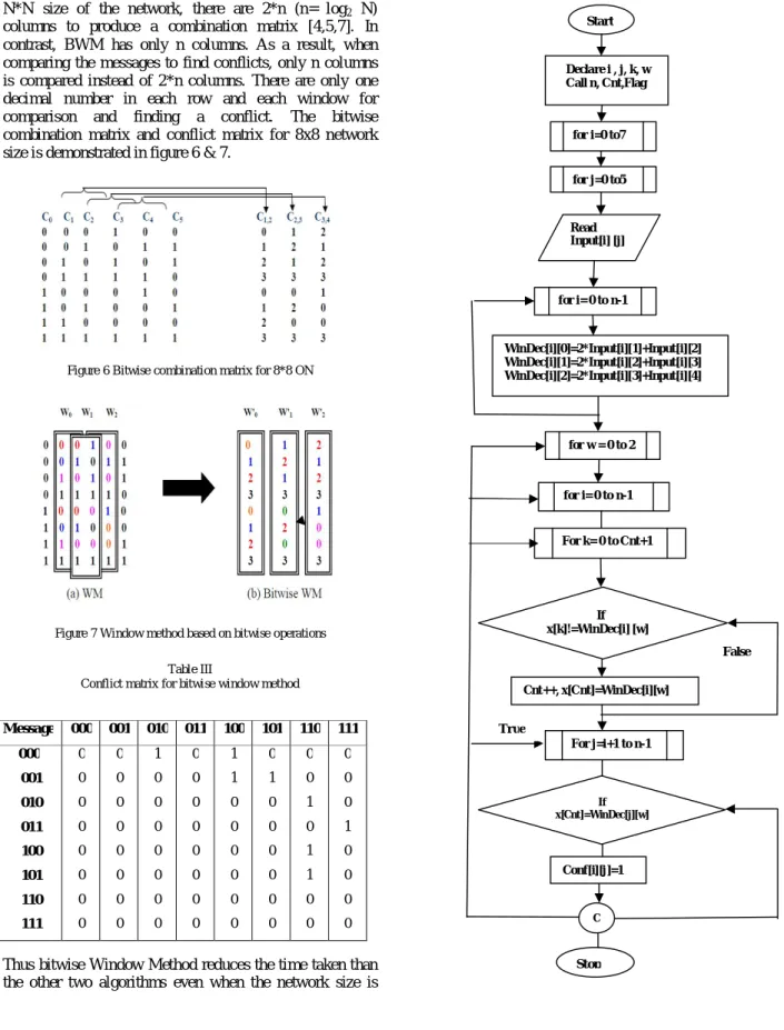
converted to decimal. When all of these are converted to decimal, the number of columns is reduced to n.In WM for N*N size of the network, there are 2*n (n= log2 N)
columns to produce a combination matrix [4,5,7]. In contrast, BWM has only n columns. As a result, when comparing the messages to find conflicts, only n columns is compared instead of 2*n columns. There are only one decimal number in each row and each window for comparison and finding a conflict. The bitwise combination matrix and conflict matrix for 8x8 network size is demonstrated in figure 6 & 7.
Figure 6 Bitwise combination matrix for 8*8 ON
Figure 7 Window method based on bitwise operations
Table III
Conflict matrix for bitwise window method
Thus bitwise Window Method reduces the time taken than the other two algorithms even when the network size is
large. The flow chart of Bitwise window method is shown in figure 8.
Message 000 001 010 011 100 101 110 111 000 001 010 011 100 101 110 111 0 0 0 0 0 0 0 0 0 0 0 0 0 0 0 0 1 0 0 0 0 0 0 0 0 0 0 0 0 0 0 0 1 1 0 0 0 0 0 0 0 1 0 0 0 0 0 0 0 0 1 0 1 1 0 0 0 0 0 1 0 0 0 0 Start Declare i , j, k, w Call n, Cnt,Flag
for i=0 to7
for j=0 to5 Read Input[i] [j] for i= 0 to n-1 WinDec[i][0]=2*Input[i][1]+Input[i][2] WinDec[i][1]=2*Input[i][2]+Input[i][3] WinDec[i][2]=2*Input[i][3]+Input[i][4] for w = 0 to 2 for i= 0 to n-1 For k= 0 to Cnt+1 If x[k]!=WinDec[i] [w] Cnt++, x[Cnt]=WinDec[i][w] For j=i+1 to n-1 Conf[i][j]=1 C Stop If x[Cnt]=WinDec[j][w] False True
ISSN: 2249-2615 http://www.internationaljournalssrg.org
Page 30
Figure 8 Flow chart for Bitwise Window method
V.COMPARATIVE ANALYSIS
This section discusses about the evaluation of the proposed three algorithms i.e. WM, IWM & BWM.As comparing above three algorithms, in the IWM the number of windows is decrease by one than that of WM. So, it takes less time to calculate the conflicts among messages. As compare WM and BWM, the comparison is done for n
columns and in decimal format for BWM instead of 2*n columns in WM, which means that the columns is reduced to half. For comparison the messages, there is only one bit instead of n-1bits in the window. Thus comparison time of other bits is eliminated. Hence, totally the execution time is decreased, table IV shows the comparison of number of columns in windows for different size of network that are use to find out conflicts.
Table IV
Comparison of number of columns in windows use to find out conflicts in WM, IWM, BWM
Figure 9 Number of columns in windows Vs. Network size
VI.CONCLUSION
In this paper, various methods have been compared and all are implemented. All the algorithms are implemented in C. It has been observed that the improved window method take lesser time to find conflicts as compared to window method. The average number of columns for comparison in
window is 10, IWM is 8 & in BWM it is 5.Therefore it is clear that number of column is reduced to half in BWM. Therefore total time of execution is also reduced. Hence efficient message routing algorithms directly affect the performance of communication networks.
REFERENCES
[1] Christopher Tocci, H. John Caufield “Optical interconnection foundation and applications” Artech house, Norwood, 1994.
[2] Pan, Y. Qiao, Yang Y., “Optical multistage interconnection networks: new challenges and approaches”, IEEE communications magazine, feature topic on optical networks, communication systems and devices, vol. 37, no. 2, 1999, pp. 50.
[3] Pan, Y. Ji, C. Lin, X. Jia, X. “Evolutionary Approach for Message Scheduling in Optical Omega Networks”, Fifth International Conference on Algorithms and Architectures for Parallel Processing (ICA3PP), (2002).
[4] Siu-Cheung Chau and Tiehong Xiao, “A new algorithm for routing and Scheduling in optical multistage interconnection networks”, Proceedings of the 4th international multi-conference on wireless and optical Communications, 2004, pp. 749-755.
[5] Mohammad, .A. A. Mohamed, O., Rozita, J., Shamala, S., “New algorithm to avoid crosstalk in optical multistage interconnection networks”, Proceeding of IEEE international conference on network, vol. 1, 2005, pp.501-504.
[6] Munir, A, mohamed, O., Rozita, J., “An efficient approach to avoid crosstalk in optical omega network”. International journal of the computer, the internet and management, vol.14, no.1, 2005, pp.50-60. [7] Farzaneh Abed , Mohamed Othman, “ Efficient window method in optical multistage interconnection networks”, Proceedings of the IEEE international conference on telecommunications and Malaysia international conference on communications, May 2006, pp.14-17. [8] F.Abed, M.Othman, “Fast method to find conflicts in optical multistage interconnection networks “ International journal of the computer, the internet and management ,vol. 16.no.1, April 2008, pp. 18-25.
[9] Tengku Dian Shahida1, Mohamed Othman, Mohamad Khazani “A fast and efficient crosstalk-free algorithm for routing in optical multistage interconnection networks”, IEEE,2008.
[10] Mohamed Othman, Farzaneh Abed, “Fast four heuristic routing algorithms in optical Multistage interconnection switch networks”, Journal of information & communication technology, vol. 2, no. 1, 2008, pp. 40-48.
[11] Er. Sandeep kaur, Er. Anantdeep, Er. Deepak Aggarwal , “Effect of crosstalk on permutation in optical multistage interconnection networks”, Journal of computing, vol. 2, Issue 4, April 2010, issue 2151-9617. Network Size WM IWM BWM 8 6 4 3 16 8 6 4 32 10 8 5 64 12 10 6 128 14 12 7 Avg 10 8 5