A REVIEW OF CURRENT SIGNATURE ANALYSIS FOR
CONDITION MONITORING OF WOUND ROTOR INDUCTION
GENERATOR AND FAULT DIAGNOSIS TECHNIQUES
E.F. Swana and W. Doorsamy
Department of Electrical and Electronics Engineering Technology, P.O. Box 17011 Doornfontein, University of Johannesburg, South Africa
Abstract: The wound-rotor induction generator (WRIG) is commonly used for wind energy application. WRIGs have simple construction, are robust with high starting torque and low starting current. Additionally, WRIGs allow rotor resistance control and can be driven at variable speeds. Despite the relative robustness of WRIGs, these machines still experience a variety of faults in practice. This paper presents an in-depth review of condition monitoring techniques for three-phase wound-rotor induction generators. Various recent research applying current signature analysis as a method of detecting and diagnosing different types of faults on both the stator and rotor of this machine is reviewed. The application of probabilistic and artificial intelligence methods such as Bayesian classification, artificial neural networks and fuzzy logic used for fault diagnosis are also investigated.
Key words: Condition monitoring, current signature analysis, intelligent fault diagnosis.
1. INTRODUCTION
Wound rotor induction generators (WRIGs) have a simple construction, are robust and can provide a stable supply when driven at varying speeds. Furthermore, WRIGs allow rotor resistance control which produces better output power over a wide range of wind conditions making it well-suited for application in wind turbines [1]. A WRIG is also flexible in application as it can be operated as an isolated generator with capacitors to supply reactive power required by the generator and loads [2]. For instance, in a grid-connected system, there may be a need for stand-alone operation arising from excessive power or stability problems in the system. Despite the relative robust nature of this machine, there are still a variety of faults that occur in practice. Recently, more attention is being given to research into WRIG condition monitoring methods. Abnormal behaviours of WRIGs under faulty conditions may cause excessive damage to the turbine and interconnected equipment, further resulting in production loss due to unscheduled repairs [3]. The possibility to diagnose a wider variety of faults at an incipient level is an ongoing challenge. In general, preventive maintenance has two major components, that is, to detect and diagnose a fault using suitable techniques and then to eliminate the condition that is reducing the performance of the machine [4]. The most common problems in induction machines are inter-turn faults on stator and rotor windings, broken rotor bars and end rings, static and dynamic air-gap irregularities, bowed shaft, bearings misalignment and mechanical imbalances [5].
The current spectrum analysis is the most popular fault detection method used on induction machines and is covered by many works [6]. However, variation in the implementation of this method of fault detection occurs
as different signal processing techniques can be employed. The signal processing techniques that are commonly used for purposes of fault diagnosis are frequency-domain based Fast Fourier Transform (FFT), the time-frequency domain Short-Term Fourier Transform (STFT) and the wavelet technique. Various fault detection and diagnosis techniques have been established by several researchers [7]. These include intelligence techniques such as Bayesian classification, artificial neural networks and fuzzy logic which are fast-becoming more popular for condition monitoring applications in general. These techniques have received significant attention in the application area of induction motors. However, there is a need for more work in this regard specifically for WRIGs. As with most areas of electrical machines, condition monitoring is also progressing toward the fourth industrial revolution. There is a greater demand for accurate, reliable and automated condition monitoring and analytics systems to be developed. Thus, intelligent or expert systems have to integrate with the aforementioned fault detection methods. In this paper, the different fault detection and diagnosis techniques are reviewed. Emphasis is placed on current spectral analysis as this technique can be used non-invasively, online and has shown to have the capability to diagnose incipient faults. Various intelligence techniques such as Bayesian classification, artificial neural networks and fuzzy logic that are becoming commonplace for condition monitoring on induction machines are also investigated as options for application on WRIGs.
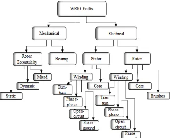
2. COMMON TYPES OF FAULTS IN WRIG The WRIG wind-based systems are likely to experience several faults categorized as mechanical and electrical. These faults are presented in figure 1. Several studies
have been carried out on the statistical data showing frequency of fault occurrence generally on induction motors. According to IEEE standard 493-1997, the summary statistics of fault frequency on induction motor faults are presented in table 1 [8]. Additionally, the survey by Electric Power Research Institute (EPRI) provides similar statistics [9].
Figure 1: Categorisation of typical occurring faults on WRIGs
Table 1: Summary of fault occurrence on induction motors
Types of Faults Percentage
Stator 35%
Rotor 10%
Eccentricity 10%
Bearing 40%
Other 5%
2.1 Stator winding faults
The stator winding inter-turn faults result from the shorting of one or more circuits of the stator phase windings [9]. Based on the previous studies, it has been shown that stator faults contribute 30%-40% of faults occurring in the electrical failure category. The main causes of these faults is insulation failure which can be due to high winding temperature or stator core temperature, slack core lamination, oil contamination, short circuit or starting stresses, electrical discharges and leakage in cooling system [10].
The insulation deterioration may create phase-to-phase or phase-to-ground faults, which alters the symmetry of the stator windings [11]. Phase faults are mostly characterised by high fault currents which makes it possible for detection. However, turn-to-turn faults with low fault current levels on the windings are more difficult to detect [12].
2.2 Rotor winding faults
The inter-turn fault on rotor phase windings is shorting of one of the phases and categorised under electrical failures [3, 13]. The main causes of rotor faults are insulation deterioration or thermal stress due to excessively high temperatures caused by overload and/or imbalance, magnetic stresses due to electromagnetic field, noise and vibration, dynamic stress due to shaft torque, and cyclic stress [4]. Insulation failure results in imbalance in the winding resistances. Furthermore, unbalanced magnetic forces and external resistors connected via the slip-ring may lead to overheating that will bend the side of the shaft with less Joule heating. This typically results in eccentricity and vibration [14].
2.3 Eccentricity faults
Eccentricity faults are air-gap irregularities occurring when the air-gap distance between the rotor and the stator is unequal. Three different types of such irregularities occur, namely: static, dynamic and mixed eccentricity faults [10]. For static eccentricity fault, the axis of rotation coincides with axis of the rotor and the position of the minimum radial air-gap is fixed. For dynamic eccentricity faults, the axis of rotation does not coincide with the axis of stator and the position of minimum air-gap follows the rotation of the rotor. Mixed eccentricity results from a combination of both static and dynamic eccentricity faults. These faults are categorized under mechanical failures [11]. Static eccentricity is caused by inaccurate positioning of the rotor or stator. Dynamic eccentricity faults are caused by bearing wear, mechanical resonance at critical speeds, shaft misalignment and unbalanced torque [15]. Eccentricity faults cause a steady unbalanced magnetic pull in one direction which results in bearing wear, vibration, and may lead to bowing of the shaft [12, 15, 16].
2.3 Bearing faults
Bearing faults are categorised as mechanical faults and are the most commonly occurring, accounting for about 40%-50% of the total faults occurring in rotating electrical machines. The temperatures of the bearing lubricant, surface and housing increase when there is bearing failure. Cracking of bearings occurs when material weariness causes small pieces to break from the bearing [4, 17]. In oil-lubricated journal-bearings, the shaft load is supported by the oil film pressure between the shaft and bearing as presented in [18]. Journal bearings are more reliable because there is no direct contact between the shaft and bearing, however these are usually only used in large machines rated above 500kW. Despite being more reliable than rolling-element bearings, journal-type bearings still suffer deterioration and failure [18]. The main causes of bearing faults are misalignment and unbalanced magnetic pull. Other causes are improper cleaning of the part prior to assembly and presence of foreign particles or impurities [7]. These
root causes may lead to eccentricity faults due to increased vibration [10]. Furthermore, bearing faults may lead to radial motion between the rotor and the stator which may cause speed fluctuations [11].
3. CONDITION MONITORING TECHNIQUES There are four modes of condition monitoring- namely: chemical, thermal, mechanical and electrical.
3.1 Chemical monitoring
Insulation deterioration results from high temperatures thereby yielding a large number of chemical products in gas, liquid and/or solid states. Chemical monitoring can be used for insulation deterioration by detecting the presence of these chemical products [19]. The detection of gas from the insulation seems to be the simplest and generally applied in induction machines [20]. The charges in the gas are collected on the electrode and flow through an external electrometer amplifier circuit and detected by a reduced output voltage from the amplifier. Other induction motors uses oil-lubricated rolling element bearings with a continuous oil supply. The oil-lubrication deterioration includes chemical products from the bearings and seals. Techniques to determine early signs of insulation wear and extreme heating includes measurement of the emission of gases such as carbon monoxide and other hydrocarbons [14, 21]. However, the detection conditions for these techniques are challenging and renders the chemical analyses complex and costly.
3.2 Thermal monitoring
Thermal monitoring has three different approaches which uses embedded temperature detectors for local measurements, thermal imaging for the hot spot detection and measurement of coolant fluids [22]. Temperature measurement is commonly used in condition monitoring of induction motors. Temperature signals are typically used to monitor specific areas of the stator core and bearing [23]. Thermal modelling such as finite element analysis based model, and lumped parameter thermal model have been applied. Finite element analysis based models are more accurate, however the complexity of the computational work is proportional to the complexity of the geometrical body. Lumped parameter thermal model require less computational work and its accuracy depends on the number of thermally homogenous bodies used [14].
3.3 Mechanical monitoring
Mechanical method usually comprise monitoring of vibration, noise discharges, torsional oscillation and shock pulses
.
The interrelation faults are bearing misalignment, air-gap eccentricity and that will turn arouse vibration. Furthermore, several types of accelerometers are existing for measuring vibration such as piezoelectric transducer [24]. When faults occur, someof the system dynamics fluctuate, resulting in significant deviations in the vibration patterns [25]. By employing suitable data analysis algorithms, it is possible to detect changes in vibration signal caused by faulty components in induction motor. However it requires invasive sensors for vibration signals and data acquisition for WRIG [26].
3.4 Electrical monitoring
Electrical monitoring uses spectral analyses components including flux, current, voltage and power. These spectral analyses enable incipient fault diagnoses. Incipient diagnoses enables proactive maintenance. The employment of steady-state spectral components are the most common monitoring techniques of various diagnostic of induction machine [6, 27]. Electrical monitoring is the most progressive mode of electrical rotating machines, due to its ninvasive technique, on-line, remote monitoring, and accurate detection of electrical & mechanical faults [28, 29].
4. SIGNATURE ANALYSIS TECHNIQUES Signature analysis falls under the electrical category of condition monitoring as it employs electrical parameters of the machine for detection and/or diagnosis of problems. This method is more desirable because it is non-invasive and can be applied online. Current signature analysis (CSA) has the advantages that it is very easy to apply, cost effective, accurate and efficient due to its sensor-less method, hence it is the most commonly used technique [9, 30]. Typically, this method uses frequency spectrum analysis of the phase currents of the machine to identify occurrence of irregularities in the harmonics relative to those that are inherent to healthy spectrum. The studies indicate that it is best to apply CSA at full load conditions, therefore it may not be employed on offline machines [31].
4.1 CSA - Stator faults
The CSA may be applied for stator or rotor winding inter-turn faults of the WRIG. This method is based on the frequency components that are the characteristics of inter-turn faults [6]. The inter-inter-turn fault simulated on the stator windings by H. Douglas et al [9] applied the CSA for the identification of stator current spectral components related to the fault. The technique was applied on the stator winding of the wound induction generator operating as a doubly-fed induction generator. The frequency components that are used for CSA detection are presented by equation (1) [32]:
(1) where fst = stator frequency components, f1 = supply
frequency,n = 1,2,3… , k = 1,3,5,…, p = pole-pairs and
s = slip. Popa et al applied CSA with the unbalanced phases using unbalanced resistive and inductive on the
stator winding of DFIG [32]. The results present the change of the stator current phase angle, where the fault is detected and has occurred.
4.2 CSA – Rotor faults
The CSA has been applied for broken rotor bars, this has been achieved by several researchers by observing stator currents frequency spectrum [6]. The inter-turn short circuit rotor fault simulation results and experimental results for a DFIG were presented by Rehman et al [5], with the results showing that the current distributed is asymmetrical. It becomes clearer as the number of shorted turns increases. The CSA applied on a WRIM for rotor asymmetries by Antinino-Daviu et al [31], shows the higher the asymmetrical conditions, the higher the magnitude. The presence of fault harmonics near the fifth harmonic were also located. The similar results to [31] were obtained by Djurovic et al [33] on a WRIG for rotor asymmetries.
4.3 CSA – Eccentricity faults
Ishkova et al presented that the harmonic frequencies for eccentricity as presented by equation (2) [27]:
(2) where fec = eccentricity frequency, fg= supply frequency,
R = number of rotor bars, s = slip, p = pole-pairs, nd =±
1, nws = 1,3,5, (order of stator time harmonics). In the
case where there is presence of static eccentricity nd is
zero and for dynamic eccentricity nd is an integer [15].
The eccentricity fault can be detected in WRIG using CSA by monitoring the specific frequency components. Based on the research using DFIG by Faiz and Moosavi [34], the frequencies that are multiples of three, cannot occur in a balanced three phase machine. Although, it has been indicated that only a specific grouping of pole-pair and rotor slot number will provide rise to significant frequency components associated to static or dynamic eccentricity and is given by equation (3).
(3) where R = number of rotor bars, p = pole-pair, m±q = 0,1,2,3,…; r = 0 or 1; k = 1 or 2. For very week cases, k = 2 and can only be visible under small load conditions. The results presented for a squirrel cage induction motor by [16], indicate the magnitude of the frequency components as given by equation (2). The results were presented and shows the CSA of induction machine with 38.46% static and 20% dynamic eccentricity for a three-phase machine. Therefore the magnitudes of the frequency components as results of load changes are always larger than those of eccentricity harmonics. Shukla et al [30], have shown the effects of combined static and dynamic eccentricity with low frequency
components near the fundamental for a squirrel cage induction motor.
4.4 CSA – Bearing faults
Bearing faults can be detected with CSA by detection of frequency components in the current spectrum. These frequency components f0 and f1 can be determined using
equation (4) and (5) as explained in [7].
(4) (5) where f0 = lower frequency, f1 = upper frequency, n =
number of balls in the bearings and frm = rotor mechanical
frequency. Damion [26], presented simulation and experimental results with a hole drilled in the middle of the bearing outer race of a WRIG. The stator current data was collected and the results shows no major effect in current signature spectrum. Although, the magnitude of the fault is very high. However, the fault frequencies are showing clearer increase for the frequency components with respect to healthy operation results. The holes were drilled in the axial and radial direction and the current spectra for oil-whirl on the squirrel cage induction motor show clear increase in the current components within the oil-whirl sideband frequency range [18].
5. ARTIFICIAL INTELLIGENCE METHODS The artificial intelligence methods have been developed to automate the diagnosis stage as decision making tools and probably indicate fault condition by locating the main sources [11]. These techniques are classified as Bayesian classification, artificial neural networks (ANN), fuzzy logic and expert systems.
5.1 Bayesian classification
The Bayesian classification is a machine learning technique that applies logical calculus for making decisions under uncertainty. The advantages of Bayesian classification its strong theoretical foundation and mathematical computation to make predictions, which makes it more transparent and easily accessible relative to other similar techniques. Furthermore, it may be used together with other classifiers to improve accuracy and performance for prediction [35, 36]. Bayesian classification employs Bayes theorem which is an algebraic model from fundamental of probability of hypothesis (H) and evidence (E) is expressed [37]:
(4)
where Pr(H) and Pr(H|E) are the prior and posterior
probabilities, Pr(E|H) and Pr(E) are likelihood and
classifier in relation to others is that if an instance is predicted to fall into a certain fault category, it offers the additional quantitative measure of the classification [37]. The classifier yields a probability associated with each instance thereby giving an indication of accuracy as well as if there is a need to improve it through additional learning instances. The Naïve Bayes classifier (NBC) is efficient in terms of time, CPU usage and memory. NBC performs well even with small training sets. This classifier also applies strong independence assumptions and works using an independent feature model [38]. Previous researchers perform classification with Naïve Bayes classifier on bearing faults on permanent magnet synchronous machines where the posterior probability is presented [17, 39]. Other previously research tested the functionality of the classifier by generating the training data using FEM and the behaviours recorded for healthy and eccentricity and rotor inter-turn short circuit fault conditions on squirrel cage induction motor and synchronous generators [37]. Probability is assigned to diagnosis, so this assists with quantifying uncertainty in condition assessment.
5.2 Artificial neural networks
Artificial neural network (ANN) technique is a computational intelligence method with an ability to accumulate and assembly data processing. This method is formed of processing units known as neurons which are arranged inside in a structure similar to brain process. This method also needs training for all possible operating conditions of the machine [11, 13]. The frequency components of the current data are extracted by the pre-processor and are classified into four classifications based on importance level with the rule-based frequency filter [40]. The incoming data is being classified by ANN technique. Then the fault is regarded as the signature that falls outside the trained clusters [4]. Toma et al, [13] applied inter-turn faults on both the stator and rotor of a WRIG and the ANN was used for the classification of different faults. The inter-turn faults on the stator of an induction motor were also tested at different levels using ANN [36].
5.3 Fuzzy logic
Based on classifying signals into a series of bands (fuzzy values), this technique make decisions instead of healthy or faulty based on single threshold [30]. In the case of a broken rotor bar side band amplitude, the machine could be classified healthy, marginal or faulty. Fuzzy logic permits merging data collected from different signals together to more accurate judgement concerning the health of the machine [4]. Fuzzy logic is an appropriate method for systems with mathematical model which is not easily driven. It has been applied by several researchers recently for condition monitoring. Navarro applied this method for machine bearing faults. More than one signal were used to detect bearing fault correctly
[11]. Other researchers developed a computational intelligence program for condition monitoring of vibration signal on induction machines. The recorded data from the vibration sensors was applied to verify the presence of faults and action would take place to protect further damage of the machine. This method has been also applied on the stator current, bearing frequency and eccentricity faults [10].
6. RECOMMENDATIONS
Condition monitoring methods have been developed and studied by several researchers particularly for application on induction motors. The current signature analysis has proven to be the most commonly used mode of fault detection. However, the application of techniques relating this mode has received less attention on wound-rotor induction generators. Analysis of the voltage signature on motors is typically not used a mode of fault detection. Thus far, application of voltage signature analyses have been restricted to analysis of the neutral voltage in motors and search coil voltages on generators and motors. Therefore, it is recommended that further research and application of these techniques be done specifically for WRIGs. Furthermore, the voltage signature analyses where the induced voltages on the stator windings could provide a better mode of fault detection and diagnosis for WRIGs. To fully detect and diagnose the condition of the machines, condition monitoring systems should be able to collect multiple data acquired. The multiple data acquired will provide system accuracy corresponding to the condition of the machine. This data should be taken into account as this is needed for the progress of condition monitoring on electrical rotating machines in general.
7. CONCLUSION
The review of inter-turn stator and rotor windings faults as electrical category, eccentricity and bearing faults as mechanical category in induction machine has been presented. The condition monitoring techniques classified as chemical, thermal vibration and electrical are reviewed. The emphasis was on current spectral analysis technique as non-invasive, online and the literature shows that it is capable of detecting incipient faults. The intelligence systems for fault automation namely; Bayesian classification, artificial neural network and fuzzy logic are reviewed. Application of the reviewed techniques have received significant attention on induction motors. However, the literature indicates that insufficient research has been done thus far on the application of these techniques on WRIGs.
8. REFERENCES
[1] C. P. Mbo’o and K. Hameyer, “Perfomance of wound rotor
induction generators with the combination of input voltage and slip power control”, Russian Electrical Engineering, vol. 85, no. 6, pp. 403-417, May/June 2017.
[2] I. Boldea,“Variable speed generators”, Taylor & Francis Group, vol. 52, no. 5, pp. 22-28.
[3] D. Shah, S. Nandi, P. Neti “Stator inter-turn fault detection of a doubly-fed induction generator using rotor current and search coil
voltage signature analysis”, IEEE Transactions on Industry
Applications, vol. 45, no. 5, pp. 1831-1842, September/October 2009.
[4] D. Agrawal, N. Yadav, and S. Saini “Condition monitoring of
slip-ring induction motor”, IJIRAE, vol. 2, no. 3, pp. 78-84, March 2015.
[5] A.U. Rehman, Y. Chen, L. Wang, Y. Zhao, Y. Yonghong, C.
Yonghong, T. Tanaka, “Experimental research and analysis on
rotor winding inter-turn circuit fault in DFIG”, IEEE, pp. 164-167,
2016.
[6] N. Mehala, R. Dahiya “Condition monitoring methods, failure
identification and analysis for induction machines”, Internatonal Journal of Circuits, Systems and Signal Processing, vol. 3, no. 1, pp. 10-17, 2009.
[7] M.E.H. Benbouzid and G. B. Kliman, “What stator current
processing-based technique to use for induction motor rotor faults
diagnosis?”, IEEE Transaction on Energy Conversion, vol. 18, no.
2, pp. 238-244, June 2003.
[8] IEEE Std 493-2007, “Recommended practice for the design of
reliable industrial and commercial power systems”, pp. 272-273, 2007.
[9] H Douglas, P. Pillay, P. Barendse, “The Detection of inter-turn stator faults in doubly-fed induction generators”, IEEE, 2005.
[10] S. Nandi, H.A. Toliyat, and X. Li “Condition monitoring and fault
diagnosis of electrical machines - a review”, IEEE Transactions on Energy Conversion, vol. 20, no. 4, pp. 719-729, December 2005.
[11] A. Bellini, F. Filippetti, C. Tassoni, G.A. Capolino “Advances in
diagnostic techniques for induction machines”, IEEE Transactions
on Industrial Electronics, vol. 55, no. 12, pp. 4169-4125, December 2008.
[12] T. Vaimann and A. Kallaste “Condition monitoring of electrical
machines - a review”, ReseachGate, May 2014.
[13] S. Toma, L. Capocchi, and G.A. Capolino “Wound rotor
induction generator inter-turn short-circuits diagnosis using a new
digital neural networks”, IEEE Transactions on Industrial
Electronics, Institute of Electrical and Electronics Engineers, vol. 60, no. 9, No.4, pp. 4043-4052, 2013.
[14] P. Tavner, L. Ran, J. Penman and H. Sedding, “Condition
monitoring of rotating electrical machines”, IET Power and
Energy Series 56, pp. 127-189, 2008.
[15] S. Nandi, R.M.Bharadwaj, and H.A. Toliyat, “Performance
analysis of a three-phase induction motor under incipient mixed
eccentricity condition” IEEE Transaction on Energy Conversion,
vol. 17, no. 3, pp. 392-399, September 2002.
[16] S. Nandi, S. Ahmed, and H. A. Toliyat, “Detection of rotor slot and other eccentricity related harmonics in a three-phase induction
motor with different rotor cages” IEEE Transaction on Energy
Conversion, vol. 16, no. 3, pp.253-260 September 2001.
[17] C. P. Mbo’o and K. Hameye, “Fault diagnosis of bearing damage
by means of the linear discriminant analysis of stator current
features from the frequency selection”, IEEE Transactions on
Industry Applications, vol. 52, no. 5, pp. 3861-3868, September/October 2016.
[18] J. Jung, Y. Park, S. B. Lee, C.H. Cho, K. Kim, E.J. Wiedenbrug
and M. Teska, “Mornitoring journal-bearing faults making use of
motor current signature snalysis for snduction sotors”, IEEE
Industry Applications Magazine, pp. 12-21,July /August 2017.
[19] P. J. Tavner, “Review of condition monitoring of rotating
electrical machines”, IET Electric Power Applications, vol. 2, no.
4, pp. 215-247, 2008.
[20] C.C. Carson, S.C. Barton, and F.S. Echeverria, “Immediate
warning of local overheating in electric machines by the detection
of pyrolysis products”, IEEE Transactions on Power Apparatus
and Systems, vol. 92, No. 1, pp. 533-542, 1973.
[21] F. Filippetti, G. Franceschini, C. Tassoni, and P. Vas, “Recent developments of induction motor drives fault diagnosis using AI
techniques”, IEEE Transactions on Industrial Electronics, vol. 47,
no. 5 pp. 994-1004, October 2000.
[22] A. Boglietti, A. Cavagnino, D. Station, M. Shanel, M. Mueller and
C. Mejuto, “Evolution and modern approaches for thermal
analysis of electrical machines”, IEEE Transactions on Industrial
Electronics, vol.56, no.3, pp. 871-882, March 2009.
[23] D. J. T. Siyambalapitiya, P. G. McLaren, and P. J. Tavner,
“Transient thermal characteristics of induction machine rotor
cage”, IEEE Transactions on Energy Conversion, vol. 3, pp.
849-854, 1988.
[24] S. Djurovic, D. Vilchis-Rodriguez and A.C. Smith, “Vibration
monitoring of a wound rotor induction machine fault detection”,
IEEE, pp. 1906-1912, 2012.
[25] G.G. Yen and K.C. Lin, “Wavelet packet feature extraction for
vibration monitoring”, IEEE Transaction on Industrial
Electronics, vol. 47, no. 3, pp. 650-666, 2000.
[26] D.S. Vilchis-Rodriguez, S. Djurovic and A.C. Smith, “Wound
rotor induction generator bearing faut modelling and detection using stator current analysis”, IET Renew. Power Gener., no. 4, pp. 330-340, 2013.
[27] I. Ishkova and O.Vitek, “Analysis of induction motor faults by means of monitoring the current and magnetic flux density
spectrums”, IEEEInternational Symposium on Power Electronics,
Electrical Drives, Automation and Motion, pp. 611-616, 2016.
[28] Z. Ye and W. Bin, “A review on induction motor online fault
diagnosis”, Power Electronics and Motion Control Conference
Proceedings, vol. 3, pp. 1353-1358, 2000.
[29] K. Teotrakool, M. J. Devaney, and L. Eren, “Adjustable-Speed
drive bear-fault detection via wavelet packet decomposition”, IEEE Transactions on Instrumentation and measurement, vol. 58, no. 8, pp. 2747-2754, 2009.
[30] S. Shukla, M. Jha, and M.F. Qureshi, “Motor current signature
analysis for fault diagnosis and condition monitoring of induction
motor using interval type-2 Fuzzy logic”, IJISET-International
Journal of Innovative Science, Engineering & Technology, vol. 1, no. 5, pp. 84-94, July 2014.
[31] J. A. Daviu, A. Q. Lopez, V.C. Alarcon and C.G. Abellan,
“Reliability detection of rotor winding asymmetries in wound
rotor induction motors via integral current analysis”, IEEE
Transactions on Industry Applications, vol. 53, no. 3, pp. 2040-2048, May/June 2017.
[32] L. M. Popa, B.B. Jensen, E. Ritchie and I. Boldea, “Condition
monitoring of wind generators”, IEEE, pp. 1839-1846, 2003.
[33] S. Djurovic, C.J. Crabtree, P.J. Tavner, A.C. Smith “Condition
monitoring of wind turbine induction generators with rotor electrical asymmetry”, IET Renew. Power Gener., vol. 6, no. 4, pp. 207-216, 2012.
[34] J. Faiz and S.M.M. Moosavi, “Detection of mixed eccentricity
fault in DFIG based on reactive power spectrum”, IET Electr. Power Appl. 2017, vol. 11, no. 6, pp. 1076-1084.
[35] A. Rahman, U. Qamar “Baysesian classifiers based combination
model for automatic test classification”, IEEE, pp. 63-67, 2016. [36] F. van der Heijden, R.P.W. Duin, D. de Ridder and D.M.J. Tax
“Classification, parameter estimation and state estimation”, John Wiley & Sons, Ltd, pp. 13-43,2004.
[37] W. Doorsamy and W.A. Cronje, “Optimisation of shaft voltages
based condition monitoring in generators using a Bayesian
approach”, 7th IET International Conference on Power Electronics
(PEMD), Machines and Drives, Manchester, UK, April 2014..
[38] F. Taroni, A. Biedermann, S. Bozza, P. Garbolino and C. Aitken
“Bayesian networks for inference and decision analysis in forensic science, 2nd edition”, John Wiley & Sons, Ltd, pp. 1-432014.
[39] C.P. Mbo’o and K. Hameyer, “Bearing damage diagnosis by
means of the linear discrimination analysis of stator current
feature”, IEEE, pp. 296-302, 2015.
[40] J. Seshadrinath, B. Singh and B. K. Panigrahi, “Incipient interturn
fault diagnosis in induction machines using an analytic
wavelet-based optimized Bayesian inference”, IEEE Transactions on
Neural Networks and Learning Systems, vol. 25, no. 5, pp. 990-1001, May 2014.