Wind Load Provisions of the Revised Building Code in Japan
Hisashi Okada1) , Yasuo Okuda2) and Hitomitsu Kikitsu3)
Abstract
This paper describes the new wind load provisions in the revised Japanese building code. The provisions were established in June, 2000 and enforced immediately. In the reform, design wind loads were defined on the results of extreme statistical analysis of wind velocities. Various new technical concepts such as terrain categories were introduced in the reform. In the revision works, simplification of the expressions was carried out as well as removal of unclearness on the criteria. In this paper major revision works are presented in this paper.
Key words:
Building code, Design wind speed, Terrain category
Wind pressure coeffic ient
1. INTRODUCTION
The Japanese Building Code is composed of the Building Standard Law, the Building Standard Law Enforcement Order, etc. The Building Standard Law, in which objectives of the code, definitions of terms, fundamental concepts and so on were described, was revised in 1998. The revision was the one toward into the performance-based regulation. Following the revision, technical regulations such as load provisions, structural calculation provisions, etc. were reformed in 2000. They are in the Building Standard Law Enforcement Orders (cabinet orders), the Building Standard Law Enforcement Regulations (Ministry of Land, Infrastructure and Transportation [= The former is Ministry of Construction] orders) and Notifications of Ministry of Construction. The revision on wind load provisions was very drastic, but it was based on AIJ recommendation1). In this paper, major technical works that were carried out for the revision are presented.
2. NEW WIND LOAD PROVISION
The radical revision of the wind load provisions was carried out for the new building code. The revision was based on AIJ recommendation. The main revisions are those on levels of load, clear separation of loads into for structural frames and for external building components, introduction of exposure factor and introduction of gust effect factor.
(1) Level of wind load
In the old provisions, wind load level was based on a record at Muroto promontory in a historical huge typhoon, “Muroto” in 1934. We have a lot of data at present, which can give us reliable estimation of expected value of wind speed. So 1)Director, Structural Engineering Department, Building Research Institute, Tsukuba, Ibaraki 305-0802, Japan
2) Senior Researcher, Ditto
3)Chief Official, Building Guidance Division, Housing Bureau, Ministry of Land, Infrastructure and Transportation, Kasumigaseki, Tokyo, 100-8918, Japan
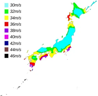
Figure 1 Map of datum wind speed 30m/s 32m/s 34m/s 36m/s 38m/s 40m/s 42m/s 44m/s 46m/s
the statistical analysis was carried out. Utilizing the result, Datum wind speed was prescribed on 50 years return period values in each place in Japan in the new provisions. Datum wind speed was defined as 10 minute average wind speed at 10m height above the ground over the flat open terrain. Taking uncertainty of typhoons into consideration, the minimum wind speed for datum wind speed was set. As the result, it is ranged from 30 to 46m/s. A map for datum wind speed is shown in figure 1.
Design wind load for no damage was prescribed on datum wind speed. Design wind load for no collapse design was prescribed as 1.6 times of the no damage design wind load. They are corresponding to 50 years and 500 years return periods values respectively.
(2) Load estimation formula
Wind loads for no damage design are given by the following formulas. The formula for structural frames is f o f r f E G V C W =0.6 2 2 (1)
where, Wf = wind load (N/m2), Er =vertical distribution coefficient for mean wind speed, Gf =gust effect factor, V0 = datum wind speed (m/s) and Cf =wind force coefficient.
While the formula for external building components is
f c q C
W = ⋅ ˆ (2)
where, Wc = wind load (N/m2), q=mean velocity pressure=0.6Er2Vo2 andCˆ =peak wind f force coefficient.
(3) Category for exposure factor
Terrain categories are defined with descriptive expressions and/or photographs showing the typical examples in AIJ recommendation as well as the other Standards2),3). The definition was thought to have a fear to produce misjudgment. Hence, the clear definition from the viewpoint of administrative building control was required and developed as follows.
The terrain categories are regulated with whether the site is inside of the city planning area or not, building height and the distance from sea front or lakefront. Figure 2 shows
diagrammatic ally the categories.
The area of Category I is designated in the area of Category II and the area of Category IV is designated in III by regional governments.
In AIJ recommendation, Category V where tall buildings heavily concentrate is categorized. But it was not categorized in the provisions because it was decided not to be necessary from the viewpoint of building control.
(4) Vertical distribution co. for mean wind speed Er or vertical distribution coefficient for mean wind speed is given with the following equation.
b G b G b Z H Z H Z H Z Z Er > = ≤ = α α 7 . 1 7 . 1 (3)
where, H = mean height of roof, and the other parameters are shown in table 1. Figure 3 shows the figures of Er. Table 1 Parameters of Er Terrain category Zb (m) ZG(m) α I 5 250 0.10 II 5 350 0.15 III 5 450 0.20 IV 10 550 0.27
Figure 2 Categories of exposure factor
Ⅱ 13m
Ⅲ
(a) Outside of city planning area
Ⅱ 31m
13m Ⅲ
0m 200m 500m
Distance from shoreline or lakefront
(b) Inside of city planning area Height of building Height of building
0 100 200 300 400 500 600 700 0.00 0.50 1.00 1.50 2.00 Er Height (m) Terrain Category Ⅰ Ⅱ Ⅲ Ⅳ
Figure 3 Er (=Vertical distribution coefficient for mean wind speed)
(5) Gust effect factor
Gust effect factor is used to convert 10-minute average velocity pressure to instantaneous wind force. Dynamic effect such as resonance between dynamic behavior of structural frame and wind load fluctuation is taken into consideration with the gust factor. Table 2 shows gust effect factors prescribed in the provisions. The gust effect factor was derived with the detailed procedure II of AIJ recommendation, assuming the following values;
Datum wind speed ; 35m/s
Building; Aspect ratio =1 , 2 and 4 Natural frequency; 40/HT (Hz),
where, HT = building height(m)
Damping coefficient =0.02 The provisions prescribe wind tunnel tests or actual measurements are available to determine gust effect factor.
Table 2 Gust effect factor Mean height of roof Terrain category H≤10m 10<H<40m 40m≤H I 2.0 1.8 II 2.2 2.0 III 2.5 2.1 IV 3.1 due to linear interpolation 2.3 (6)Wind Force coefficient
Wind force coefficient for structural frame is
defined as follows. pi pe
f C C
C = − (4)
where, Cpe = external wind pressure coefficient, Cpi = internal wind pressure coefficient. External wind pressure coefficients for the following shape buildings and structures are shown in the provisions. They are closed buildings having pitched roof, flat roof,
mono-slope roof, arched roof, multi span pitched roof and multi span saw-tooth roof, unenclosed buildings having pitched roof, free roofs of pitched roof and wing type roof, lattice structure, netlike structure and cylindrical structure.
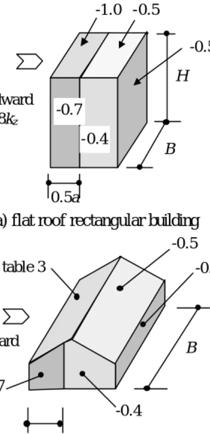
Figure 4 shows the external wind pressure coefficients of closed building having flat roof and pitched roof as the examples.
0.5a B H -0.5 -0.5 -1.0 -0.4 -0.7 windward 0.8kz
(a) flat roof rectangular building -0.4 -0.5 -0.7 -0.4 0.5a B windward 0.8kz see table 3
(b) pitched roof rectangular building Figure 4 External wind pressure coefficient for
closed type building
In Figure 4, H, B and a in Figure 4 are defined as follows;
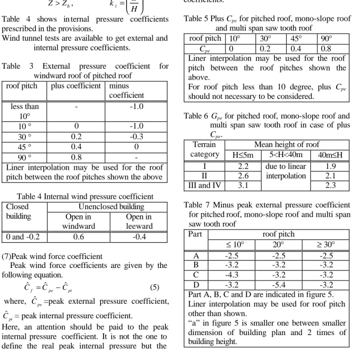
B = breadth of building a = min(B, 2H) And kz is defined as follows; in case of H ≤Zb kz =1.0 in case of H >Zb, b Z Z ≤ , α = 2 H Z k b z Z >Zb, α = 2 H Z kz
Table 4 shows in ternal pressure coefficients prescribed in the provisions.
Wind tunnel tests are available to get external and internal pressure coefficients.
Table 3 External pressure coefficient for windward roof of pitched roof
roof pitch plus coefficient minus coefficient less than 10° - -1.0 10 ° 0 -1.0 30 ° 0.2 -0.3 45 ° 0.4 0 90 ° 0.8 -
Liner interpolation may be used for the roof pitch between the roof pitches shown the above
Table 4 Internal wind pressure coefficient Unenclosed building Closed building Open in windward Open in leeward 0 and -0.2 0.6 -0.4
(7)Peak wind force coefficient
Peak wind force coefficients are given by the following equation.
pi pe
f C C
Cˆ = ˆ − ˆ (5)
where, Cˆpe=peak external pressure coefficient,
pi
Cˆ = peak internal pressure coefficient.
Here, an attention should be paid to the peak internal pressure coefficient. It is not the one to define the real peak internal pressure but the contribution of internal pressure to the maximum instantaneous wind forces.
Wind tunnel tests are available to determine the peak wind force coefficients, too.
External peak pressures coefficients are given by the products of Cpe and Gpe in case they are plus. But in case that they are minus, they are given by external peak pressure coefficients themselves. Table 5 and 6 show the Cpe and Gpe for pitched roofs, mono-slope roofs and multi span saw tooth roofs. Table 7 shows the minus peak external pressure coefficients for pitched roofs. Table 8 shows peak internal pressure coefficients.
Table 5 Plus Cpe for pitched roof, mono-slope roof and multi span saw tooth roof
roof pitch 10° 30° 45° 90° Cpe 0 0.2 0.4 0.8 Liner interpolation may be used for the roof pitch between the roof pitches shown the above.
For roof pitch less than 10 degree, plus Cpe should not necessary to be considered.
Table 6 Gpe for pitched roof, mono-slope roof and multi span saw tooth roof in case of plus Cpe.
Mean height of roof Terrain category H≤5m 5<H<40m 40m≤H I 2.2 1.9 II 2.6 2.1 III and IV 3.1 due to linear interpolation 2.3 Table 7 Minus peak external pressure coefficient
for pitched roof, mono-slope roof and multi span saw tooth roof
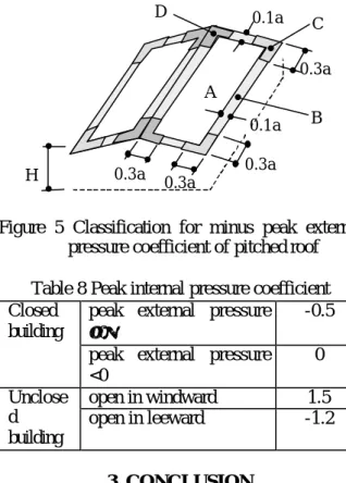
roof pitch Part ≤ 10° 20° ≥ 30° A -2.5 -2.5 -2.5 B -3.2 -3.2 -3.2 C -4.3 -3.2 -3.2 D -3.2 -5.4 -3.2
Part A, B, C and D are indicated in figure 5. Liner interpolation may be used for roof pitch other than shown.
“a” in figure 5 is smaller one between smaller dimension of building plan and 2 times of building height.
A
B C D
H 0.3a 0.3a 0.3a
0.3a 0.1a
0.1a
Figure 5 Classification for minus peak external pressure coefficient of pitched roof Table 8 Peak internal pressure coefficient
peak external pressure ≥0
-0.5 Closed
building
peak external pressure <0 0 open in windward 1.5 Unclose d building open in leeward -1.2 3. CONCLUSION
Wind load provisions in the new Japanese Building code were described.
In the wind load provisions, terrain categories were defined with clear definitions from the viewpoint of building control.
The design wind speeds were based on 50 years return period for no damage design and 500 years return period for no collapse. They are 10-minute average wind speed at 10m height above the ground over flat open terrain.
To develop the new provisions, some simplifications were carried out. As one of the results, gust effect factors for structural frame were defined with terrain category and building height.
Wind load estimation formulas were prescribed for structural frame and for external building components separately.
Some wind pressure coefficients shown in the provisions were presented here.
Reference
1) “AIJ Recommendations for Loads on Buildings” Architectural Institute of Japan, 1996 2) “Australian Standard, AS1170.2-1989, SAA Loading Code Part 2”, 1989