Voice over Packet Tutorial
Definition
Voice over packet is the process of transmitting voice information, which is traditionally transmitted over plain old telephone service (POTS), over packet networks such as Internet, ATM and frame relay.
Tutorial Overview
Voice over the Internet. Voice over ATM. Voice over frame relay. Thinking back just a few years, most of us can admit we would have found it
difficult to imagine that these telecommunications applications would be the increasing market force that they are today. So much so that forecasts for the year 2002 estimate that close to 20% of all domestic phone traffic will be carried over data lines, up from less than just 1% now.
Organizations around the world want to reduce rising communications costs. The consolidation of separate voice and data networks offers an opportunity for significant savings. Accordingly, the challenge of
integrating voice and data networks is becoming a rising priority for many network managers. Organizations are pursuing solutions that will enable them to take advantage of excess capacity on broadband networks for voice and data transmission as well as utilize the Internet and company Intranets as alternatives to costlier mediums.
Truly wonderful services and products still require a voice engineered access gateway linking the data and telephony networks. Inside will be a comprehensive technology set that reduces the impairments caused by sending voice over data networks that were not designed to handle it. Voice processing will need to handle greater and variable delays and cancel the echoes that will be introduced from the telephony side so the voice will not sound mechanical. It will also need to mask the gaps caused by dropped packets during congestion. The packet processing (data) side of the gateway will have to adapt to variable networks and conditions and ensure the right end-to-end connections. Also, an understanding of how to handle call set up translation for different types of networks, connections, and interworking is essential for competent handling of every call.
A voice over packet application meets the challenges of combining legacy voice networks and packet networks by allowing both voice and signaling information to be transported over the packet network. This tutorial discusses a general class of packet networks since the modular software objects allow networks such as ATM, frame relay, and Internet/Intranet (IP) to transport voice. An overview of an embedded software approach to voice over packet applications is presented.
Topics
1. Applications Enabled by the Transmission of Voice over Packet Networks
2. Quality of Service Issues Unique to Packet Networks 3. An Embedded Software Approach to Voice over Packet 4. Voice Packet Software Module
5. Signaling, Protocol, and Management Software Modules 6. Summary
7. Self-Test
8. Glossary of Terms and Acronyms
1. Applications Enabled by the
Transmission of Voice over Packet
Networks
A wide variety of applications are enabled by the transmission of voice over packet networks. This tutorial will explore three examples of these applications.
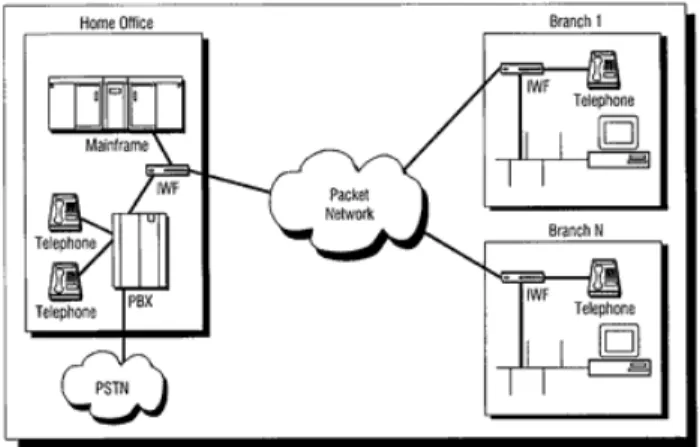
Figure 1. Branch Office Application
The first application, shown in Figure 1, is a network configuration of an organization with many branch offices (e.g., a bank) that wants to reduce costs and combine traffic to provide voice and data access to the main office. This is accomplished by using a packet network to provide standard data transmission while at the same time enhancing it to carry voice traffic along with the data. Typically, this network configuration will benefit if the voice traffic is compressed due to the low bandwidth available for this access application. Voice over packet provides the interworking function (IWF), which is the physical implementation of the hardware and software that allows the transmission of combined voice and data over the packet network. The interfaces the IWF must support in this case are analog interfaces that directly connect to telephones or key systems. The IWF must emulate the functions of both a PBX for the telephony terminals at the branches as well as the functions of the telephony terminals for the PBX at the home office. The IWF accomplishes this by implementing signaling software that performs these functions.
Figure 2. Interoffice Trunking Application
A second application of voice over packet, shown in Figure 2, is a trunking application. In this scenario, an organization wants to send voice traffic between two locations over the packet network and replace the tie trunks used to connect the PBXs at the locations. This application usually requires the IWF to support a higher capacity digital channel than the branch application, such as a T1/E1 interface of 1.544 or 2.048 Mbps. The IWF emulates the signaling functions of a PBX, resulting in significant savings in companies' communications costs.
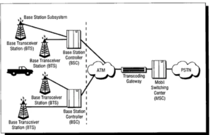
Figure 3. Cellular Network Interworking Application
A third application of voice over packet software is interworking with cellular networks, as shown in Figure 3. The voice data in a digital cellular network is already compressed and packetized for transmission over the air by the cellular phone. Packet networks can then transmit the
compressed cellular voice packet, saving a tremendous amount of bandwidth. The IWF provides the transcoding function required to convert the cellular voice data to the format required by the public switched telephone network (PSTN).
2. Quality of Service Issues Unique to
Packet Networks
The advantages of reduced cost and bandwidth savings of carrying voice over packet networks are associated with some quality of service issues unique to packet networks. These issues are explored below.
Delay
Delay causes two problems — echo and talker overlap. Echo is caused by the signal reflections of the speaker's voice from the far end telephone equipment back into the speaker's ear. Echo becomes a significant
problem when the round-trip delay becomes greater than 50 milliseconds. Since echo is perceived as a significant quality problem, voice over packet systems must address the need for echo control and implement some means of echo cancellation. Talker overlap (or the problem of one talker stepping on the other talker's speech) becomes significant if the one-way delay becomes greater than 250 milliseconds. The end-to-end delay budget is, therefore, the major constraint and driving requirement for reducing delay through a packet network.
The following are sources of delay in an end-to-end voice over packet call: Accumulation delay (sometimes called algorithmic delay): This delay is caused by the need to collect a frame of voice samples to be processed by the voice coder. It is related to the type of voice coder used and varies from a single sample time (.125 microseconds) to many milliseconds. A
representative list of standard voice coders and their frame times follows: G.726 - ADPCM (16, 24, 32, 40 Kbps) - .125 microseconds
G.728 - LD-CELP(16 Kbps) - 2.5 milliseconds G.729 - CS- ACELP (8 Kbps) - 10 milliseconds
G.723.1 - Multi Rate Coder (5.3, 6.3 Kbps) - 30 milliseconds
• Processing delay: This delay is caused by the actual process of encoding and collecting the encoded samples into a packet for transmission over the packet network. The encoding delay is a function of both the processor execution time and the type of algorithm used. Often, multiple voice coder frames will be collected in a single packet to reduce the packet network overhead. For example, three frames of G.729 codewords, equaling 30 milliseconds of speech, may be collected and packed into a single packet.
• Network Delay: This delay is caused by the physical medium and protocols used to transmit the voice data and by the buffers used to remove packet jitter on the receive side. Network delay is a function of the capacity of the links in the network and the processing that occurs as the packets transit the network. The jitter buffers add delay which is used to remove the packet delay variation that each packet is subjected to as it transits the packet network. This delay can be a significant part of the overall delay since packet delay variations can be as high as 70 msec to 100 msec in some frame relay networks and IP networks.
Jitter
The delay problem is compounded by the need to remove jitter, a variable inter-packet timing caused by the network a packet traverses. Removing jitter requires collecting packets and holding them long enough to allow the slowest packets to arrive in time to be played in the correct sequence. This causes additional delay. The two conflicting goals of minimizing delay and removing jitter have engendered various schemes to adapt the jitter buffer size to match the time varying requirements of network jitter removal. This adaptation has the explicit goal of minimizing the size and delay of the jitter buffer while at the same time preventing buffer
underflow caused by jitter.
Two approaches to adapting the jitter buffer size are detailed below. The approach selected will depend on the type of network the packets are traversing.
• The first approach is to measure the variation of packet level in the jitter buffer over a period of time and to incrementally adapt the buffer size to match the calculated jitter. This approach works best with networks that provide a consistent jitter performance over time (e.g., ATM networks).
• The second approach is to count the number of packets that arrive late and create a ratio of these packets to the number of packets that are successfully processed. This ratio is then used to adjust the jitter buffer to target a predetermined allowable late packet ratio. This approach works best with the networks with highly variable packet inter-arrival intervals (e.g., IP networks).
In addition to the techniques described above, the network must be configured and managed to provide minimal delay and jitter, enabling a consistent quality of service.
Lost Packet Compensation
Lost packets can be an even more severe problem, depending on the type of packet network that is being used. Because IP networks do not
guarantee service, they will usually exhibit a much higher incidence of lost voice packets than ATM networks. In current IP networks, all voice frames are treated like data. Under peak loads and congestion, voice frames will be dropped equally with data frames. The data frames, however, are not time-sensitive and dropped packets can be appropriately corrected through the process of retransmission. Lost voice packets, however, cannot be dealt with in this manner.
Some schemes used by voice over packet software to address the problem of lost frames are listed below:
• Interpolate for lost speech packets by replaying the last packet received during the interval when the lost packet was supposed to be played out. This is a simple method that fills the time between non-contiguous speech frames. It works well when the incidence of lost frames is infrequent. It does not work very well when there are a number of lost packets in a row or a burst of lost packets.
• Send redundant information at the expense of bandwidth utilization. The basic approach replicates and sends the nth packet of voice information along with the (n+1)th packet. This method has the advantage of being able to exactly correct for the lost packet. However, this approach uses more bandwidth and creates greater delay.
• A hybrid approach uses a much lower bandwidth voice coder to provide redundant information carried along in the (n+1)th packet. This reduces the problem of the extra bandwidth required but fails to solve the problem of delay.
Echo Compensation
Echo in a telephone network is caused by signal reflections generated by the hybrid circuit that converts between a 4-wire circuit (a separate transmit and receive pair) and a 2-wire circuit (a single transmit and receive pair). These reflections of the speaker's voice are heard in the speaker's ear. Echo is present even in a conventional circuit-switched telephone network. However, it is acceptable because the round-trip
delays through the network are smaller than 50 msec and the echo is masked by the normal side tone every telephone generates.
Echo becomes a problem in voice over packet networks because the round-trip delay through the network is almost always greater than 50 msec. Thus, echo cancellation techniques are always used. ITU standard G.165 defines performance requirements that are currently required for echo cancellers. The ITU is defining much more stringent performance requirements in the G.IEC specification.
Echo is generated toward the packet network from the telephone network. The echo canceller compares the voice data received from the packet
network with voice data being transmitted to the packet network. The echo from the telephone network hybrid is removed by a digital filter on the transmit path into the packet network.
3. An Embedded Software Approach to
Voice over Packet
Two major types of information must be handled in order to interface telephony equipment to a packet network — voice and signaling
information. An overview of a software architecture approach to voice over packet is presented below.
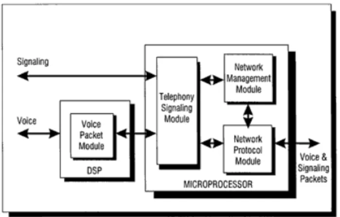
Figure 4. Voice over Packet Software Architecture
As shown in Figure 4, voice over packet software interfaces to both
streams of information from the telephony network and converts them to a single stream of packets transmitted to the packet network. The software functions are divided into four general areas:
• Voice packet software: This software, typically run on a DSP, prepares voice samples for transmission over the packet network. Its components perform tone detection and
generation, echo cancellation, voice compression, voice activity detection, jitter removal, resampling, and voice packetization. • Telephony signaling gateway software: This software interacts
with the telephony equipment, translating signaling into state changes used by the network protocol module (described below) to set up connections. These state changes are on-hook, off-hook, trunk seizure, etc. This software supports E&M (wink, delay and immediate), loop or ground start FXS and FXO, ISDN BRI/PRI and QSIG.
• Network protocol software: This software processes signaling information and converts it from the telephony signaling
protocols to the specific packet signaling protocol used to set up connections over the packet network (e.g., Q.933 and voice over FR signaling). It also adds protocol headers to both voice and signaling packets before transmission into the packet network. • Network management software: This software provides the
voice management interface to configure and maintain the other modules of the voice over packet system. All management
information is defined in ASN.1 and complies with SNMP V1 syntax.
The software is partitioned to provide a well-defined interface to the DSP software usable for multiple voice packet protocols and applications. The DSP processes voice data and passes voice packets to the microprocessor with generic voice headers. The microprocessor is responsible for moving voice packets and adapting the generic voice headers to the specific voice packet protocol that is called for by the application, such as real time protocol (RTP), voice over frame relay (VOFR), and voice telephony over ATM (VTOA). The microprocessor also processes signaling information and converts it from supported telephony signaling protocols to the packet network signaling protocol (e.g., H.323 (IP), frame relay, or ATM
signaling).
This partitioning provides a clean interface between the generic voice processing functions — such as compression, echo cancellation, and voice activity detection — and the application specific signaling and voice protocol processing.
4. Voice Packet Software Module
This section describes the functions performed by voice packet software, which is primarily responsible for processing the voice data. This function is usually performed in a digital signal processor (DSP). The voice packet software functions are as follows:
• PCM interface: Receives PCM samples from the digital interface and forwards them to appropriate DSP software modules for processing. Forwards processed PCM samples received from various DSP software modules to the digital interface. Performs continuous phase resampling of output samples to the digital interface to avoid sample slips.
• Tone generator: Generates DTMF tones and call progress tones under command of the host (e.g., telephone, fax, modem, PBX or telephone switch). Configurable for support of U.S. and international tones.
• Echo canceller: Performs G.165 compliant echo cancellation on sampled, full-duplex voice port signals. Programmable range of tail lengths.
• Voice activation detector/idle noise measurement: Monitors the received signal for voice activity. When no activity is detected for the configured period of time, the software informs the packet voice protocol. This prevents the encoder output from being transported across the network when there is silence, resulting in additional bandwidth savings. This software also measures the idle noise characteristics of the telephony
interface. It reports this information to the packet voice protocol in order to relay this information to the remote end for noise generation when no voice is present.
• Tone detector: Detects the reception of DTMF tones and
performs voice/fax discrimination. Detected tones are reported to the host so that the appropriate speech or fax functions are activated.
• Voice codec software: Compresses the voice data for transmission over the packet data. Capable of numerous compression ratios through the modular architecture. A compression ratio of 8:1 is achievable with the G.729 voice codec (thus, the normal 64 Kbps PCM signal is transmitted using only 8 Kbps).
• Fax software: Performs a fax relay function by demodulating PCM data, extracting the relevant information, and packing the fax line scan data into frames for transmission over the packet network. Significant bandwidth savings can be achieved by this process.
• Adaptive playout unit: Buffers voice packets received from the packet network and sends them to the voice codec for playout. The following features are supported:
• A FIFO buffer that stores voice codewords before playout removes timing jitter from the incoming packet sequence • A continuous-phase resampler that removes timing
frequency offset without causing packet slips or loss of data for voice or voiceband modem signals
• A timing jitter measurement that allows adaptive control of FIFO delay
The voice packetization protocols use a sequence number field in the transmit packet stream to maintain temporal integrity of voice during playout. Using this approach, the transmitter inserts the contents of a free-running, modulo-16 packet counter into each transmitted packet, allowing the receiver to detect lost packets and to properly reproduce silence intervals during playout.
• Packet voice protocol: Encapsulates compressed voice and fax data for end-to-end transmission over a backbone network between two ports.
• Message processing unit: Coordinates the exchange of monitor and control information between the DSP and host via a
mailbox mechanism. Information exchanged includes software downline load, configuration data, and status reporting.
• Real-time portability environment: Provides the operating environment for the software residing on the DSP. Provides synchronization functions, task management, memory management, and timer management.
Figure 5. Voice Packet Module
images/bigure05.gifimages/bigure05.gif
Figure 5 diagrams the architecture of the referenced DSP software. The DSP software processes PCM samples from the telephony interface and converts them to a digital format suitable for transmission through a packet network.
5. Signaling, Protocol, and
Management Software Modules
The voice over packet software performs telephony signaling to detect the presence of a new call and to collect address (dial digit) information, which is used by the system to route a call to a destination port. It supports a wide variety of telephony signaling protocols and can be
adaptable to many environments. The software and configuration data for the voice card can be downloaded from a network management system to allow customization, easy installation, and remote upgrades.
The software interacts with the DSP for tone detection and generation as well as mode of operation control based on the line supervision, and
interacts with the telephony interface for signaling functions. The software receives configuration data from the network management agent and utilizes operating system services.
Telephony Signaling Gateway Software
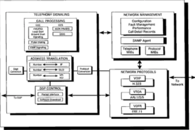
Figure 6. Signaling Software
images/bigure06.gifimages/bigure06.gif
Figure 6 diagrams the architecture of the signaling software. The software consists of the following components:
• Telephony interface unit software: Periodically monitors the signaling interfaces of the module and provides basic
debouncing and rotary digit collection for the interface. • Signaling protocol unit: Contains the state machines
implementing the various telephony signaling protocols such as E&M.
• Network control unit: Maps telephony signaling information into a format compatible with the packet voice session establishment signaling protocol.
• Address translation unit: Maps the E.164 dial address to an address that can be used by the packet network (e.g., an IP address or a DLCI for a frame relay network).
• DSP interface driver: Relays control information between the host microprocessor and DSPs.
• DSP downline loader: Responsible for downline load of the DSPs at start-up, configuration update, or mode changes (e.g.,
switching from voice mode to fax mode when fax tones are detected).
Network Protocol Software
• IP signaling stack: H.323 call control and transport software, including H.225, H.245 and RTP/RTCP transport protocol, TCP, IP, UDP protocols.
• ATM signaling protocol stack: ATM forum VTOA voice
encapsulation protocol. ATM Forum compliant user-network interface (UNI) signaling protocol stack for establishing, maintaining, and clearing point and point-to-multipoint switched virtual connections (SVCs).
• Frame relay protocol stack: Frame relay forum VOFR voice encapsulation protocol, PVC and SVC support, local
management interface (LMI), congestion management and traffic monitoring, CIR enforcement and congestion.
Network Management Software
The network management software consists of three major services addressed in the MIB:
• Physical interface to the telephone endpoint
• Voice channel service for processing signaling on a voice
channel and converting between PCM samples and compressed voice packets
• Call control service for parsing call control information and establishing calls between telephony endpoints
6. Summary
A voice over packet software architecture using an embedded software approach has been described for the interworking of legacy telephony systems and packet networks. Some of the key features enabling this application to function successfully are as follows:
• An adaptive playout to minimize the effect of jitter
• Features that address lost packet compensation and echo cancellation
• A flexible DSP system architecture that manages multiple channels per single DSP
Carrying voice over packet networks provides the most bandwidth-efficient method of integrating these divergent technologies. While the challenges to this integration are substantial, the potential savings make the investment in a quality implementation compelling.
7. Self-Test
1. The consolidation of separate voice and data networks offers an opportunity for:
n
m l
k
j a. Utilization of extra broadband bandwidth for voice and data transmission
n
m l
k
j b. Reduced delay over a telephone call
n
m l
k
j c. Reduction in computer and telephone hardware requirements 2. IP, ATM and frame relay are examples of:
n
m l
k
j a. Public switched telephone network protocols
n m l k j b. Packet networks n m l k j c. Radio frequencies
3. By enabling their products with embedded software, communications equipment manufacturers can:
n
m l
k
j a. Eliminate the need to develop for different standards and protocols
n
m l
k
j b. Reduce development costs
n
m l
k
j c. Decrease time to market
n
m l
k
j d. All of the above
4. A quality of service issue unique to packet networks is:
n m l k j a. Interworking n m l k j b. Compression n m l k j c. Jitter
5. In a voice over packet system, network management software provides what function? n m l k
j a. Processes signaling information and converts it from the telephony signaling protocols to the specific packet signaling protocol used to set up connections over the packet network
n
m l
k
j b. Provides the voice management interface to configure and maintain the other modules of the voice over packet system
n
m l
k
j c. Interacts with the telephony equipment, translating signaling into state changes to set up connections
6. Talker overlap, the problem of one talker stepping on the other talker's speech, is a result of:
n
m l
k
j a. One-way delay of data exceeding 250 msec
n
m l
k
j b. Delayed packets being released prematurely
n
m l
k
j c. Lost packets having been poorly compensated
7. Signal reflections generated by the circuit that converts between a 4-wire circuit and a 2-4-wire circuit can result in:
n m l k j a. Jitter n m l k j b. Echo n m l k j c. Delay
8. Developers seeking to incorporate voice over packet technology face which of the following challenges:
n
m l
k
j a. Still-evolving technical standards
n
m l
k
j b. Network phenomena such as delay, jitter, echo, and lost packets
n
m l
k
j c. Integrating incompatible technologies
n
m l
k
9. Voice over packet technology may be used to transfer information over both broadband and wireless networks.
n m l k j a. True n m l k j b. False
10. During a voice over packet call, the idle noise present on the public switched telephone network (when no voices are speaking) must be synthesized by comfort noise generation to provide users with a normal telephone experience.
n m l k j a. True n m l k j b. False
Correct Answers
Correct answers are in boldface.
1. The consolidation of separate voice and data networks offers an opportunity for:
a. Utilization of extra broadband bandwidth for voice and data transmission
b. Reduced delay over a telephone call
c. Reduction in computer and telephone hardware requirements See "Tutorial Overview", Paragraph 1.
2. IP, ATM and frame relay are examples of:
a. Public switched telephone network protocols
b. Packet networks
c. Radio frequencies
See "Tutorial Overview", Paragraph 2.
3. By enabling their products with embedded software, communications equipment manufacturers can:
a. Eliminate the need to develop for different standards and protocols b. Reduce development costs
c. Decrease time to market
d. All of the above
4. A quality of service issue unique to packet networks is: a. Interworking
b. Compression
c. Jitter
See Topic 2, "Jitter".
5. In a voice over packet system, network management software provides what function?
a. Processes signaling information and converts it from the telephony signaling protocols to the specific packet signaling protocol used to set up connections over the packet network
b.Provides the voice management interface to configure and maintain the other modules of the voice over packet system
c. Interacts with the telephony equipment, translating signaling into state changes to set up connections
See Topic 3, Paragraph 2, Point 4.
6. Talker overlap, the problem of one talker stepping on the other talker's speech, is a result of:
a. One-way delay of data exceeding 250 msec
b. Delayed packets being released prematurely c. Lost packets having been poorly compensated See Topic 2, Paragraph 2.
7. Signal reflections generated by the circuit that converts between a 4-wire circuit and a 2-4-wire circuit can result in:
a. Jitter
b. Echo
c. Delay
8. Developers seeking to incorporate voice over packet technology face which of the following challenges:
a. Still-evolving technical standards
b. Network phenomena such as delay, jitter, echo, and lost packets c. Integrating incompatible technologies
d. All of the above
9. Voice over packet technology may be used to transfer information over both broadband and wireless networks.
a. True
b. False
10. During a voice over packet call, the idle noise present on the public switched telephone network (when no voices are speaking) must be synthesized by comfort noise generation to provide users with a normal telephone experience.
a. True
b. False
8. Glossary of Terms and Acronyms
Asynchronous Transfer Mode (ATM)
A high-speed, high-volume, packet-switching transmission protocol standard. The purpose of ATM is to provide a high-speed, low-delay, multiplexing and switching network to support any type of user traffic, such as voice, data, or video applications. ATM currently accommodates transmission speeds from 64 Kbps to 622 Mbps.
Codec A device or program that converts (encodes) analog signals into a form for transmission on a digital circuit. The digital signal is then decoded back to analog at the receiving end of the
transmission link. A codec performs both pulse code modulation and demodulation.
Digital Signal Processor (DSP)
A device similar to a microprocessor but specifically designed to process digitized analog signals in real time.
Embedded
Software Embedded software operates inside dedicated services.Embedded communications software is real-time
communications software that enables products to connect to communications networks. It allows communications
equipment manufacturers to eliminate the need to develop for different standards and protocols, reduce development costs, and decrease time to market.
Frame Relay A wideband (64 Kbps to 1.544 Mbps) packet-based data interface standard that transmits bursts of data over wide area networks (WANs). Frame relay networks provide end users with a high-speed virtual private network (VPN) capable of supporting applications with large bit-rate transmission requirements.
Internet
Protocol (IP) The Internet protocol that defines the unit of information passedbetween systems that provide a basis packet delivery service. IP permits the exchange of traffic between two host computers without any prior call setup.
Interworking
Function (IWF) The physical implementation of the hardware and software thatallows the transmission of combined voice and data over the packet network.
Base (MIB) systems. The MIB defines the syntax of the information carried with the network management protocols.
Packet
Switching A method of transmitting units of data (called packets) through amesh network. There is no physical circuit established between endpoints; instead data is divided into small blocks with a
common marked destination so different routes can efficiently be taken to avoid overloading a single facility or path.
Public Switched Telephone
Network (PSTN)
The worldwide common carrier voice telephone network accessible to anyone with telephone access privileges. Provides circuit switching between public users.
Private Branch
Exchange (PBX) A customer premise communication switch used to connectcustomer telephones (and related equipment) to phone company central office lines (trunks) and to switch internal calls within the customer's telephone system. Modern PBXs offer numerous software-controlled features such as call forwarding and call pickup.
Pulse Code Modulation (PCM)
A method of quantizing audio-range analog signals into a digital form for transmission in digital communications systems or for processing in DSP. Effectively the same as analog-to-digital conversion.
Plain Old Telephone Service (POTS)
The basic service supplying standard single-line telephones, telephone lines and access to the public switched telephone network (PSTN). Featureless; receive and place calls only.
Voice Over
Packet The process of transmitting voice information, which istraditionally transmitted over plain old telephone service
(POTS), over packet networks such as Internet, ATM and frame relay.
9. Products and Services
Telogy Networks is the leading provider of embedded communications software to global equipment manufacturers. Only Telogy Networks offers a complete solution to manufacturers who need to integrate voice, data, and fax over packet and wireless networks. As one of the few embedded software companies with both microprocessor and DSP expertise, Telogy offers its customers truly acomprehensive product solutions.
Telogy Networks has two principal product lines: Golden GatewayTM voice
over packet and ActiveAirTM wireless. With Golden Gateway and ActiveAir,
manufacturers can reduce their time to market, lessen technological risk, minimize support requirements, and reduce development costs.
Integrating Telogy's embedded communications software lets
manufacturers focus on getting to market first with the product features customers want most.
Award-winning Golden Gateway voice over packet software enables routers, switches and access devices to send voice, real-time fax and data over Internet, frame relay, and ATM networks. Industry watchers are taking note of Telogy's successes. Inter@ctive Week observed, "Jitter and packet loss are other traditional problems with sending voice over packet-based networks, but advances from software providers such as Telogy Networks, Inc. have virtually eliminated these problems." (Inter@ctive Week; July 21, 1997)
ActiveAir wireless communications software enables cellular and PCS handsets and base stations to communicate using the latest digital standards. TDMA (IS-136) and "digitally-enabled" AMPS, the first ActiveAir products, will soon be joined by CDMA (IS-95) and GSM products. ActiveAir wireless products enable manufacturers to embed voice, fax, and data communications connectivity into wireless handsets, base stations, and test equipment operating across cellular and personal communications services (PCS). ActiveAir products provide signal, protocol, and call processing functions in accordance with international standards. Its embedded software architecture facilitates rapid product introduction, multi-mode phones, and enhanced features.