Fault-Tolerant Distributed Clock Generation in VLSI Systems-on-Chip
Matthias F¨ugger, Ulrich Schmid, Gottfried Fuchs Vienna University of Technology
Email: {fuegger, s, fuchs}@ecs.tuwien.ac.at
Gerald Kempf Austrian Aerospace GmbH Email: gerald.kempf@space.at
Abstract
This paper1introduces a simple fault-tolerant tick generation algorithm based on Srikanth & Toueg’s consistent
broadcast primitive that can be directly implemented in VLSI using asynchronous digital logic. The need for adaption originates from two peculiarities of hardware implementations: (i) Fine-grained parallel asynchronous computations, which undermines the concept of atomic steps common to all distributed computing models, and (ii) very limited resources, which makes even apparently simple operations prohibitively costly. We prove that the resulting algorithm is correct, and derive performance metrics like worst case precision and accuracy. Moreover, we outline the major building blocks of our synthesizable VHDL implementation and provide some measurement results from our FPGA prototype. Our results hence provide the required basis for investigating robust alternatives to synchronous clocking in VLSI Systems-on-Chip and similar applications.
Keywords: Fault-tolerant distributed algorithms, VLSI Systems-on-Chip, fault-tolerant tick generation, clock synchronization.
Number of Pages: 20
Corresponding Author: Matthias F¨ugger, email: fuegger@ecs.tuwien.ac.at, tel: ++43 (1) 58801-18252; fax: ++43 (1) 58801-18297, address: Technische Universit¨at Wien, Embedded Computing Systems Group (E182/2), Treitlstrasse 3/2, A-1040 Vienna, Austria
1Supported by the Austrian bm:vit FIT-IT projectDARTS(proj. no. 809456-SCK/SAI) and the Austrian FWF projectTheta(proj. no.
1 Motivation
Shrinking feature sizes and increasing clock speeds are the most visible signs of the tremendous advances in VLSI design, which will accommodate billions of transistors on a single chip in the near future [12]. This comes at the price of increased system-level complexity, however: With today’s deep submicron technology with GHz clock speeds, wiring delays dominate transistor switching delays, and signals cannot traverse the whole die within a single clock cycle any more. Moreover, the reduced voltage swing needed for high clock speeds and low power consumption dramatically increases the adverse effects of single event upsets likeα-particle or neutron hits. The
resulting increase of the transient failure rate (soft-error rate) [17] and crosstalk sensitivity [23] has raised concerns about the dependability of future generation VLSI chips [5]. In fact, a modern VLSI chip can no longer be viewed as a monolithic block of synchronous hardware, where all state transitions occur simultaneously. Rather, VLSI chips are nowadays considered as systems of interacting subsystems — the advent of Systems-on-Chip (SoC). Due to the problems listed above, however, SoCs have much in common with the loosely-coupled distributed systems that have been studied by the fault-tolerant distributed algorithms community for decades. This paper explores whether it is possible to utilize some of this research for SoCs and similar VLSI devices.
More specifically, in the context of our DARTS-Project (http://www.ecs.tuwien.ac.at/projects/DARTS), which is a joint project between Vienna University of Technology and Austrian Aerospace, we will explore an alternative approach (patented in [26]) to synchronous clocking in VLSI chips and PCB-level system designs. As shown in Fig. 1, the idea is to replace the external quartz oscillator and the clock tree, which supplies the clock signal to the different functional units (Fui) on a traditional chip, using a GALS-like approach [4]: Every functional unit has attached a dedicated fault-tolerant tick generation block (TS-Alg), which generates the Fu’s local clock signal. In contrast to GALS, however, our approach ensures that the local clock signals of different Fu’s are closely synchronized to each other. To accomplish this, all TS-Alg blocks communicate with each other over a simple “network” of clock signals (TS-Net).
This alternative clocking approach has a number of advantages, which makes it particularly promising for certain application domains: First of all, it does not need a quartz oscillator, which is an expensive and sensitive
C lo ck T re e Oscillator Fu1 Data Bus Fu3 Fu2 TS-Algs Fu1 Data Bus Fu3 Fu2 TS-Net
device (shock, vibration, temperature etc.). The generated clock always runs at the maximum speed and adapts to the current operating conditions2. Moreover, the approach tolerates transient failures in TS-Algs and TS-Net and avoids the cumbersome clock tree engineering issue [2, 9]. And last but not least, as different Fus are driven by slightly different clock signals, our approach alleviates EM radiation and ground bouncing problems [19] that typically plague devices using synchronous clocking.
Contributions: This paper shows that it is indeed possible to adapt fault-tolerant distributed algorithms to the particular needs of VLSI implementations. More specifically: (i) We adapt the simple variant of Srikanth & Toueg’s [27] consistent broadcasting introduced in [29] to the peculiarities of VLSI hardware implementations, namely, inherent fine-grained parallelism and very limited resources. Our major modifications are the enforce-ment of some atomic actions (interlocking) via implicit handshaking, and the replaceenforce-ment of k-bit messages by anonymous rising or falling signal transitions (zero-bit messages). (ii) We provide a fault-tolerant distributed tick generation algorithm (TS-Alg), which tolerates up to f Byzantine faulty instances in a system containing n ≥3f + 2TS-Algs. Examples of Byzantine failures are spurious clock transitions or early timing failures that
are perceived inconsistently at different TS-Algs. (iii) We prove that the resulting algorithm is correct, and derive bounds for its performance metrics like worst case precision and minimal/maximal clock frequency. Since our “system-level proof” rests upon some simple properties of certain digital logic blocks only, which can be easily verified by means of standard design tools, we can guarantee the correctness of any system ofn ≥3f + 2
cor-rectly implemented TS-Algs. (iv) We provide some details of our synthesizable VHDL implementation of the algorithm, and demonstrate the feasibility of our approach by means of some measurement results obtained from an FPGA prototype system. These results will hence allow us to implement our DARTS clock generation scheme in a prototype SoC ASIC.
Related work:Asynchronous distributed systems theory has been applied to VLSI chips for decades [7]: Research on transition signaling [3], delay-insensitivity [18], micropipelines [28], etc. has in fact established a sound basis for dealing with self-timed systems [10]. However, those approaches cannot deal with failures.
Given the importance of dependability issues, there is a huge body of research work devoted to fault-tolerance in VLSI. However, the proposed techniques are very different from the “system-level approach” employed in fault-tolerant distributed algorithms: Fine-grained fault tolerance, e.g. at gate level, and error detection and recovery are the methods of choice in VLSI chips [22]. This research is hence not relevant w.r.t. our approach.
There is also a sizeable body of work devoted to hardware implementations of fault-tolerant algorithms.
Well-2Several important questions must still be answered in our DARTS-Project, however: For example, it is not clear yet how area and
power consumption of some reasonable number of TS-Algs relates to the area and power consumption of a clock tree. Researching those problems, which primarily requires comparison of suitable ASIC implementations, is outside the scope of this paper.
known examples are MAFT [13], SAFEBUS [11] and TTP [14]. However, in sharp contrast to our problem, these systems incorporate hardware assistance only. The major part of the algorithms is still implemented in conventional software and executed on general-purpose processors. Consequently, there was no need to minimize the gate-level resource consumption implied by these algorithms. Somewhat an exception is the paper [1], which shows that consensus can be solved with 1-bit messages. None of the above systems had to deal with fine-grain parallelism inherent in VLSI implementations, though.
There is also some related work on alternative clocking schemes in VLSI. Since we do not consider external clock sources in our approach, we can ignore the sizeable body of work on hardware-assisted fault-tolerant clock synchronization (see [25] for an overview) here. The few approaches for distributed clock generation without external clock sources we are aware of are essentially based on a (distributed) ring oscillator, which is formed by gates arranged in a positive feedback loop. Instead of being dictated by a quartz, the frequency of the generated clock signal is determined by the end-to-end delay of the feedback loop. In [20], a regular structure of closed loops of an odd number of inverters is used for distributed clock generation. Similarly, [8] employ local tick generation cells, arranged in a two-dimensional grid. Since clock synchronization theory [6] reveals that high connectivity is required for bounded synchronization tightness in presence of failures, however, the sparsely connected designs proposed in [8, 20] are not fault-tolerant.
2 Informal Overview
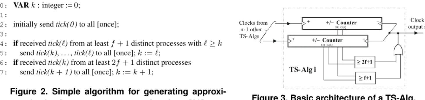
The TS-Alg developed and analyzed in this paper derives from a simple synchronizer algorithm introduced in [29]. The (core of this) algorithm, which is based on Srikanth & Toueg’s well-known consistent broadcasting primitive [16,24,27], is shown in Fig. 2. When executed in a system ofn= 3f+ 1processes (= TS-Alg instances)
with at mostf of them being Byzantine faulty, it generates a sequence of consecutive messagestick(k),k≥0, at every process. The algorithm ensures that the difference of the points in real-time when two correct processesp
andqemittick(k)is bounded by a certain constant precisionπ, which can be computed from the maximum (τ+) and minimum (τ−) of the end-to-end transmission and computation delay oftick(.)messages.
The algorithm is started by sendingtick(0)inline 2and works as follows: If a correct processpreceivesf+1
tick(`)messages (line 4), it can be sure that at least one of those was sent by a correct process. Therefore,pcan
safely catch up and sendtick(k), . . . ,tick(`). If some processpreceives2f+1tick(k)messages (line 6), one can be sure that at leastf+ 1of those will be received by every other correct process (which then executesline 4) withinε=τ+−τ−. Hence, all other correct processesq6=preceive2f+ 1tick(k)messages within anotherτ+. It follows that ifpemitstick(k)at timet, every other correctqemitstick(k)no later thant+ε+τ+. This eventually
0: VARk: integer :=0; 1:
2: initially sendtick(0)to all [once]; 3:
4: ifreceivedtick(`)from at leastf+ 1distinct processes with`≥k
5: sendtick(k), . . . ,tick(`)to all [once];k:=`;
6: ifreceivedtick(k)from at least2f+ 1distinct processes
7: sendtick(k+1)to all [once];k:=k+ 1;
Figure 2. Simple algorithm for generating approxi-mately simultaneous messages taken from [29]
– + – 2f+1 f+1 TS-Alg i Clock output i + Clocks from n-1 other TS- Algs GR GEQ GR GEQ +/– Counter +/– Counter
Figure 3. Basic architecture of a TS-Alg. guarantees a boundπ on the synchronization precision, as claimed above. Note that the algorithm automatically
adapts to the instantaneous timing characteristics of all involved computations and message transmissions. Since the algorithm in Fig. 2 looks very simple, it is tempting to conclude that it should be easy to translate into a hardware description language: Thek-th generated clock tick occurs when a process sends itstick(k)message. It turns out, however, that a number of challenging issues must be solved to accomplish this:
How to implement the TS-Net efficiently? The algorithm assumes a fully connected network, consisting of
n2 links, so anything beyond a single wire per link is considered unacceptable3. Moreover, for implementation
simplicity and performance, the information transmitted via the TS-Net must be kept to a minimum. Ideally, and almost mandatory, the TS-Net should just feed the emitted clock ticks, i.e., signal transitions, of every TS-Alg to every other TS-Alg.
How to adapt the original algorithm for zero-bit messages? By just sending anonymous signal transitions, no information except the occurrence time can be conveyed over the TS-Net. Thus, the tick numberkcontained in a
message in the algorithm of Fig. 2 must be maintained at every receiver, individually for every sender.
How to ensure atomicity of actions in a VLSI implementation?Any distributed computing model we are aware of assumes atomic computing steps at the level of a single processor. This abstraction does not apply when an algorithm is implemented directly in hardware, however, since all “computations” are done by several digital logic gates that run concurrently. Explicit synchronization (serialization of actions/interlocking) must be introduced if two local computations must not interfere with each other.
Taking into account the above issues, we arrived at the following basic architecture of a single TS-Alg shown in Fig. 3. The major building blocks of a single TS-Alg are the n−1 up/down counters, one for every of the
n−1other TS-Algs in the system. Each such device counts the difference of (i) the number of clock ticks seen
from the respective peer, and (ii) the number of clock ticks generated locally so far. It is supposed to provide two binary status signals,GRandGEQ, which are true when the counter’s actual value is>0and≥0, respectively. In
addition, we need≥f + 1and≥2f+ 1threshold circuits implementing the rules in (line 4) and (line 6) in
Fig. 2, respectively. Finally, there is a device (shown as an OR-gate in Fig. 3), which is responsible for generating the local clock ticks from the outputs of the threshold gates.
Again, the above architecture is deceptively simple. The major problem when trying to implement Fig. 3 in hardware is the lack of a common clock signal that could be used for a synchronous logic design. Rather, a (quasi) delay insensitive asynchronous implementation [10] must be devised. The major4 problem here is to distinguish
GR, GEQsignals that contributed to the previously generated tickk fromGR,GEQsignals contributing to the
next (to be generated) tick k+ 1. Our solution exploits the fact that the transitions of a binary-valued signal
must strictly alternate between low-to-high and high-to-low: We just provide independent signalsGR,GEQand threshold circuits for generating odd (k∈Nodd:= 2N+ 1) and even clock ticks (k∈Neven:= 2N).
The output of the threshold circuits (sayT HGRo andT HGEQo ) that generated the even tickkare ignored when
the next tickk+ 1 to be generated is odd. This “gap” thus allowsGRo andGEQo (which were responsible for activatingT HGRo orT HGEQo ) for tickkto first become inactive and then become active again for the tickk+ 2.
As revealed by Lemma 4.5, this is sufficient to avoid mixing up old and new instances ofGRoandGEQo.
3 The Algorithm
It has been highlighted in the previous section that even the simple algorithm presented in Fig. 2 makes use of design elements that are not available or too costly at the hardware design level. In addition, one has to account for the fact that even the simplest (= sequential) control flow comes with some delay since it actually involves sending a signal over a wire, i.e., a zero-bit FIFO message channel. In this section, we will provide the architectural design model of a TS-Alg that meets those requirements.
3.1 Signals and Zero-bit Message Channels
All components of our TS-Algs, which are digital logic blocks, deal with binary signals only. Given such a signalS[or an arbitrary boolean predicate], with possible values⊥(= logical 0, false, inactive) and>(= logical 1, true, active), we say that the event (= state transition)S−↑(t∗)resp.S−↓(t∗)occurs whenSchanges state from
⊥to>resp. from>to⊥at timet∗. The statusS(t)ofS at timet≥t∗ isS(t) = ⊥resp.S(t) = >iff the last
event at or beforetwasS−↓(t∗)resp. S−↑(t∗).
In our analysis, we will reason about events and status of binary signals [and predicates]. In order not to clutter our notation, we will employ the convention that, depending on the context of usage,S(t)will denote either
• S’s statusS(t)∈ {⊥,>}, wheretdenotes the observation time, or
Dif f rsp,q 1, sp,q1 rq,p(t) remote pipen−1
remote pipe1 local pipe1
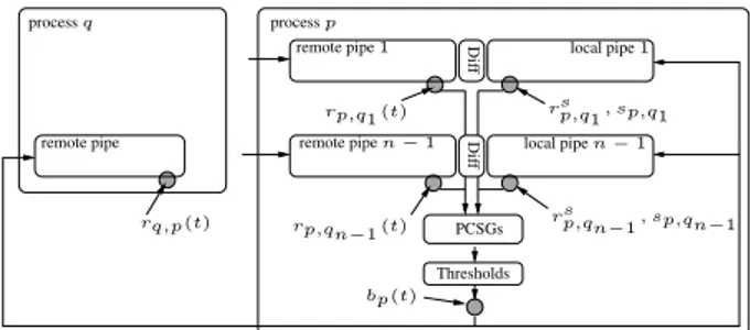
local pipen−1 processq processp rsp,qn −1, sp,qn−1 rp,q1(t) rp,qn−1 (t) bp(t) PCSGs Thresholds Dif f remote pipe
Figure 4. Architecture of a TS-Alg, including the points of observationbp(t),rp,q(t)andrsp,q(t) • the eventS−↑(t), wheretdenotes the time of the last transition to the active state>(or reset time). Note also that we will sometimes drop the timetfrom events and status if it is clear from the context.
All components in our system are interconnected by signal wires, which are modeled as reliable FIFO channels with finite delay that carry zero-bit messages. The semantics of a zero-bit message channel X is as follows:
LetXsbe the channel’s input signal, which is controlled by a single sender component. It generates the events
(= messages)Xs−↑ (t) andXs−↓ (t), wheretdenotes the sending time. The associated input stateXs(t)can
be viewed as the information content of the last message sent intoX. ChannelX’s output is fed to the receiver,
which perceives the event (= message)Xr−↑(t0)resp.Xr−↓(t0)for every sent eventXs−↑(t)resp.Xs−↓(t)
within finite timet0 ≥t. The receiving stateXr(t)at timetcan again be viewed as the information content of the
last received message. At reset timet0, the channel stateXr(t0)is initialized to⊥.
Obviously, a zero-bit message channel can only convey messages with strictly alternating content. Nevertheless, this type of communication is compatible with Lamport’s happened-before relation [15]: For matching send and receive events, it holds that Xs−↑ (t) → Xr−↑ (t0) andXs−↓ (t) → Xr−↓ (t0). To simplify the notation
when using a channelX, we will employ the convention thatX−↑ (t)andX−↓ (t)abbreviate the send events
Xs−↑(t)andXs−↓(t), respectively, whereasX(t)abbreviates the stateXr(t)at the receiving end.
3.2 TS-Alg Component and Architecture Specification
In this section we will specify the TS-Alg components’ behavior and determine their arrangement. The archi-tecture is depicted in Fig. 4. Note that a +/−counter in Fig. 3 comprises the first3components listed below.
Pairs of elastic pipes:Every TS-Alg/processpincorporatesn−1pairs of elastic pipelines (= a shift register/FIFO
for signal transitions [28]), each of which corresponds to a single remote TS-Alg/processq∈Q⊆P \ {p}. Every pair consists of a remote pipeline that can store up toS tick−↑/ tick−↓messages sent byq, and a local pipeline
that has to be chosen in accordance with Theorem 4.13.
For description and analysis purposes, we will need some notation: rp,q(t)resp.rsp,q(t)denotes the number of messages that arrived at the end of the remote resp. local pipe at time t. Moreover,sp,q(t)denotes the number of tick messages stored in the local pipeline by time t. Note carefully that those quantities are not available to
the algorithm. Rather, the algorithm uses only the binary status signalsrp,q(t) ≥rsp,q(t)andrp,q(t) > rsp,q(t)in conjunction withsp,q(t) = 1. Upon reset, all pipelines are initialized to contain a single even tick−↓message. We assume thatrp,q(t0,p) =rp,qs (t0,p) = 0andsp,q(t0,p) = 1at reset timet0,p.
Diff-Gate: To avoid the need for infinite storage, each pair of pipelines is equipped with a special circuit that removes tick messages contained in both pipes. The behavior of a Diff-Gate is as follows: Ifrp,q(t) ≥rp,qs (t)∧
sp,q(t) > 1, there is some t0 ∈ t+ [τDiff− , τDiff+ ]such that sp,q(t0) = sp,q(t0 −dt)−1, for some infinitesimally smalldt >0. Note that we are not loosing information due to this removal of “common” tick messages, since the
algorithm is only interested in the difference of the number of messages received.
Pipe Compare Signal Generators (PCSGs): There exists a dedicated detection circuit for each pair of pipes, which generates the status signals GEQo/ep,q(t) and GRo/ep,q(t). In particular, GEQop,q(t0) becomes active (i.e.,
GEQop,q(t0) = >, thereby generating the eventGEQp,qo −↑att0 if the previous state was ⊥) at some timet0 ∈
t+ [τGEQ− ;τGEQ+ ]when (i)rp,qs (t) ∈Noddand (ii)[rp,q(t)≥rsp,q(t)]∧[sp,q(t) = 1]. Similarly,GRop,q(t0)becomes active at timet0 ∈ t+ [τGR−;τGR+]when (i)rsp,q(t) ∈Noddand (ii)[rp,q(t) > rsp,q(t)]∧[sp,q(t) = 1]. The signals
GEQep,q(t)andGRep,q(t)have the same definition, except that (i) readsrsp,q(t) ∈ Nevenhere. Note that a PCSG
may become active only ifsp,q(t) = 1.
Threshold:If the number of activeGEQo/ep,q(t)resp.GRp,qo/e(t)signals exceeds the2f + 1resp.f + 1threshold, the corresponding threshold signalT HGEQo/e (t)resp.T HGRo/e(t)becomes active within[τTH−;τTH+].
Tick Broadcast: The next tick message is sent when (i) both threshold signals for the previously generated tick, say,T HGEQo andT HGRo , are inactive again and (ii) at least one threshold signalT HGEQe resp.T HGRe for the
current tick becomes active. We denote bybp(t)the number of tick messages generated by processpby timet, with
bp(t0) = 0at reset timet0. Iftkdenotes the time whenpgenerates tickk, we assume thatbp(tk) =bp(tk−dt)+1
for an infinitesimally smalldt >0, i.e.,bp(tk)gives the number of ticks including the new tickk.
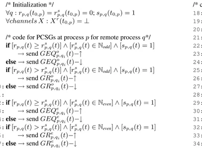
The detailed description of the TS-Alg based on our architectural model is given in Fig. 5. Note that the algorithm’s if-clauses are only evaluated when the validity of the if-clause’s premise changes, i.e., upon a state transition of the enabling condition (which also happens, by convention, upon reset). In case of the threshold gates (line 18–line 29), we conceptually assume that a (possibly idempotent) output event is sent upon any change of the state of any input.
0: /* Initialization */
1: ∀q:rp,q(t0,p) =rp,qs (t0,p) = 0;sp,q(t0,p) = 1
2: ∀channels X:Xr(t
0,p) =⊥
3:
4: /* code for PCSGs at processpfor remote processq*/
5: if[rp,q(t)≥rsp,q(t)]∧[rp,qs (t)∈Nodd]∧[sp,q(t) = 1]
6: →sendGEQop,qi(t)−↑ 7: else→sendGEQo
p,qi(t)−↓ 8: if[rp,q(t)> rsp,q(t)]∧[rp,qs (t)∈Nodd]∧[sp,q(t) = 1] 9: →sendGRo p,qi(t)−↑ 10:else→sendGRp,qo i(t)−↓ 11: 12:if[rp,q(t)≥rsp,q(t)]∧[rp,qs (t)∈Neven]∧[sp,q(t) = 1] 13: →sendGEQep,qi(t)−↑ 14:else→sendGEQe
p,qi(t)−↓
15:if[rp,q(t)> rsp,q(t)]∧[rp,qs (t)∈Neven]∧[sp,q(t) = 1]
16: →sendGRe
p,qi(t)−↑
17:else→sendGRp,qe i(t)−↓
/* code for thresholds at processp*/
18:ifGEQop,qi(t)for at least2f+ 1remote processesqi
19: →sendT Ho
GEQ−↑
20:else→sendT Ho
GEQ−↓
21:ifGRp,qo i(t)for at leastf+ 1remote processesqi
22: →sendT Ho
GR−↑
23:else→sendT HGRo −↓
24:ifGEQe
p,qi(t)for at least2f+ 1remote processesqi 25: →sendT HGEQe −↑
26:else→sendT He
GEQ−↓
27:ifGRp,qe i(t)for at leastf+ 1remote processesqi 28: →sendT HGRe −↑
29:else→sendT He
GR−↓
30:/* code for sending tick messages at processp*/
31:if[T Ho GR(t)∨T HGEQo (t)]∧ ¬[T HGRe (t)∨T HGEQe (t)] 32: →send tick−↓ 33:if[T He GR(t)∨T HGEQe (t)]∧ ¬[T HGRo (t)∨T HGEQo (t)] 34: →send tick−↑
Figure 5. TS-Alg tick generation algorithm adopted for VLSI implementations
4 Correctness Proofs
For our correctness proof and performance analysis, we employ the following system and failure model: LetP
be a set ofndistributed processes, executing TS-Algs, which communicate via simulated broadcasting (multiple
point-to-point sends) over a fully connected network of reliable zero-bit FIFO message passing links. Every link carries strictly alternating tick−↑and tick−↓messages only. The transmission delay satisfies some upper and lower bounds, which are unknown to the algorithm, i.e., introduced solely for analysis purposes: The time of a locally generated tick message to reach the end of any local pipeline is bounded by[τloc−;τloc+], whereas the time to reach the end of any remote pipeline, at any remote process, is bounded by[τrem− ;τrem+ ]. Note that this assumption has
some impact on initialization as well: Every processpcan be initialized tobp(t0,p) = rp,q(t0,p) = rsp,q(t0,p) = 0
andsp,q(t0,p) = 1even at (slightly) different reset timest0,p ∈[0;τrem− ): The lower delay boundτrem− ensures that
no tick message can be lost here. The latencies[τGEQ− ;τGEQ+ ],[τGR−;τGR+], [τDiff− ;τDiff+ ]and[τTH−;τTH+]have already been introduced earlier.
Our tick generation algorithm will allow up tof processes to fail arbitrarily, provided that the total number of processes is n ≥ 3f + 2. This is slightly more than the required lower bound of n ≥ 3f + 1 for clock
synchronization [6], but facilitates a much better precision and accuracy. In our context, the adverse power of arbitrary failures lies in the ability of a process to generate wrong (early timing failures or even spurious) clock ticks, which are perceived inconsistently at different receiver processes. Such failures may be the consequence of particle hits or electromagnetic interference, which can very well affect different receivers differently, depending upon wire length and signal detection sensitivity.
We will start our formal treatment with Definition 4.1, which will be employed frequently in our proofs.
Definition 4.1. (Direct Causality). LetI(t0) and O(t) be two events of some specific signal input and output, respectively, of a correct componentC. We say that they aredirectly causally related, denoted byI(t0)→O(t), if
they are (i) causally related and (ii) there is neither an↑- nor a↓-eventI0(t00)on the same input in between, i.e., @I0(t00) : I(t0) → I0(t00) → O(t). If the input and output eventsI(t0) andO(t) of a correct componentC with
latency∈[τC−, τC+]are directly causally related, thenτC−≤t−t0≤τ+
C.
An instrumental part in the correctness proof of the tick generation algorithm in Fig.5 is to make sure that a process generates tickk+ 1messages based on tickkmessages only, i.e., does not incorporate stale information
from earlier ticks ` < k here. This will be formalized in the following Definition 4.2. Lemma 4.3 below will
deduce some simple properties from this definition.
Definition 4.2. (Notion of Basis).Abbreviate
Pp,qGEQ,`(t) = [rp,q(t)≥rp,qs (t) =`]∧[sp,q(t) = 1]andPp,qGR,`(t) = [rp,q(t)> rp,qs (t) =`]∧[sp,q(t) = 1]. (1)
We say that correct processp’s tickk+ 1isbased oncorrect processq’s tick`, if there exists at least one of the
following chains of direct causal dependencies: Fork+ 1∈Neven,
Pp,qGEQ,`(t00) → GEQop,q(t0)→T HGEQo (t0k+1)→bp(tk+1) =k+ 1 (2)
Pp,qGR,`(t00) → GRop,q(t0)→T HGRo (t0k+1)→bp(tk+1) =k+ 1 (3)
(and analogous fork+ 1∈Nodd). A correct processp’s tickk+ 1is said to bebased ontick`if, for all correct
processesq, it is based onq’s tick`qwith`q≥`and∃qi :`qi =`.
Lemma 4.3. The time instantst0k+1andt00in the direct causal chains (2) and (3) in Definition 4.2 satisfyτTH− +
min(τGR−, τGEQ− ) ≤t0k+1−t00≤τTH+ + max(τGR+, τGEQ+ ). Moreover, the predicatePp,qGEQ,`(t)resp.Pp,qGR,`(t)holds
not only att=t00, but continues to hold true for everyt∈[t00, tk+1−τTH+ −τGEQ+ ]resp.t∈[t00, tk+1−τTH+ −τGR+],
provided those time intervals are non-empty.
Proof. The first statement of our lemma is a trivial consequence of Definition 4.1. To prove that the predicates continue to hold true during the given intervals, recall from the algorithm in Fig. 5 that tickk+1is sent at timetk+1,
i.e.,bp(tk+1) =k+ 1, iff[T HGRo (tk+1)∨T HGEQo (tk+1)]∧ ¬[T HGRe (tk+1)∨T HGEQe (tk+1)]∧bp(tk+1−dt) =
k ∈ Nodd, where dt > 0 is infinitesimally small: At least one of the threshold gates responsible for the even
tickk+ 1must be active, while both threshold gates for the previous odd tickkmust be inactive. Furthermore,
Stipulating that the event bp(tk+1) = k+ 1 occurs attk+1 implies that all enabling conditions are met. In
particular, T HGEQo resp. T HGRo must not have further changed state within the time interval(t0k+1, tk+1]. We
will show now that the predicates (1) must also maintain the same state for some time. Suppose, by way of contradiction, that e.g.Pp,qGEQ,`(t)reverted to false at some timet00 < t≤tk+1−τTH+ −τGEQ+ . Then, theGEQo
threshold gate must have generated another event T Ho
GEQ(t00k+1) (maybe an idempotent one) at time t00k+1 =
t+τGEQ+ +τTH+ ≤tk+1at latest, and clearlyT HGEQo (t00k+1)→bp(tk+1) =k+ 1. This contradicts direct causality
ofT Ho
GEQ(t0k+1)→bp(tk+1) =k+ 1, however.
Now we are ready for proving our major Lemma 4.5, which shows that every correct processp’s tickk+ 1is based on tickkonly, provided that the following Constraint 4.4 is satisfied. If this is the case, there is no danger
of mixing up new and old instances of the signalsGRo,GEQoetc.
Constraint 4.4. (Interlocking Constraint).With the abbreviations
D+=τTH+ + max(τGR+, τGEQ+ ) +τloc+ andD−=τTH− + min(τGR−, τGEQ− ) +τloc− +τDiff− (4)
it must hold thatD+≤D−+D−dis, whereDdis− =D−−τDiff− .
Lemma 4.5. (Interlocking). Provided that Constraint 4.4 holds, every correct processp’s tickk+ 1is based on
tickkonly.
Proof. The proof is by induction on the number of tick messages sent by a correct processp.
Induction basis: Tick1is based on tick0(established upon reset) only. Tick2can be based on tick1only, since
even ticks are solely generated fromGRoandGEQo—and hence from odd ticks—in the algorithm of Fig. 5. Induction step: Suppose that all ticks up to tickkare based on tickk−1, but that tickk+1generated by process pis not based on tickkbut rather on tick` < k. Assuming w.l.o.g.k∈Noddand hence`∈ {k−2, k−4, . . .}, there
must be some correct processqisatisfying (2) and/or (3), say,Pp,qGEQ,`i (t
00 qi)→GEQ o p,qi(t 0 qi)→T H o GEQ(t0k+1)→
bp(tk+1) = k+ 1according to Definition 4.2. Lemma 4.3 reveals that Pp,qGEQ,`i (t0) = [rp,qi(t
0) ≥ rs p,qi(t
0) =
`]∧[sp,qi(t
0) = 1] must evaluate to true also at timet0 witht
k+1 −t0 ≤ τTH+ +τGEQ+ ≤ τTH+ + max(τGR+, τGEQ+ ).
Hence, tick k−1 must have been received at process p’s local pipe corresponding toqi at time t00 > t0, since otherwise the first predicate inPp,qGEQ,`i (t
0)would be false att0. Since tickk−1must have been sent by processp
at timetk−1 ≥t00−τloc+ in this case, we finally arrive attk−1 > tk+1−τTH+ −max(τGR+, τGEQ+ )−τloc+ =tk+1−D+.
Since tickk−1arrives at any local pipe at ˜t ≥ tk−1+τloc− earliest, rp,qs (˜t) = k−1is obtained not before
˜
t+τDiff− , as the previous tickk−2must be removed from the local pipe beforesp,q(t0) = 1can become true. Due to the induction hypothesis, tickkis based on tickk−1only. Lemma 4.3 hence implies that tickkcan not be sent
Recall thatpcan only send tickk+1attk+1if¬[T HGRe (tk+1)∨T HGEQe (tk+1)]is true, i.e., when all threshold
gates that generated the previous tick k are inactive again. Process p generated tickk when sufficiently many
correct processesqj satisfied (2) and/or (3), i.e., contributed toT HGEQo and/orT HGRo . The latter signals can only be disabled attk+1if there exists at least one correct processqamong those, for which
¬{[rp,q(ˆtq)≥rp,qs (ˆtq)]∧[rp,qs (ˆtq) =k−1]∧[sp,q(ˆtq) = 1]} → ¬GEQep,q(t0)→ ¬T HGEQe (tk+1)
¬{[rp,q(ˆtq)> rp,qs (ˆtq)]∧[rp,qs (ˆtq) =k−1]∧[sp,q(ˆtq) = 1]} → ¬GRep,q(t0)→ ¬T HGRe (tk+1)
holds at some time ˆtq, with tk < tˆq and tˆq + min(τ−
GR, τGEQ− ) + τTH− ≤ tk+1. The first predicate can only
become true if tickkhas arrived at the local queue corresponding toqj. Thus,tk+τloc− ≤ ˆtqand hencetk+1 ≥
tk+ min(τGR−, τGEQ− ) +τTH− +τloc− =tk+D−dis.
Combining the latter results ontk+1andtk, we obtaintk+1 ≥tk−1+D−+D−dis. Substituting the result for
tk−1, we findtk+1 > tk+1−D++D−+Ddis− and henceD+ > D−+D−dis, which contradicts Constraint 4.4. Therefore, tickk+ 1cannot be based on` < kand we are done.
We will now provide a sequence of simple lemmas, which are needed for establishing our major results Theo-rem 4.11 (precision), TheoTheo-rem 4.12 (accuracy) and TheoTheo-rem 4.13 (pipeline size).
Lemma 4.6. (Maximum Frequency). No correct process can send alternating tick messages with a higher fre-quency than1/D−.
Proof. Assume that a correct processpsends tickk+ 1∈Noddat timetk+1. Because of Lemma 4.5, tickk+ 1
can only be based on tick numberk. This means thatPp,qGEQ,ki (t
0
qi) must have been true by timetk+1 −τ
−
TH −
min(τGR−, τGEQ− )simultaneously for at leastf+ 1resp.2f+ 1processesqi. Thuspmust have sent tickkby time tk≤tk+1−τTH− −τDiff− −min(τGR−, τGEQ− )−τloc− ≤tk+1−D−, whereτloc− accounts for the minimum delay to reach
the end of a local pipe andτDiff− is the minimal time for removing the previous tickk−1to achievesp,qi(t
0
qi) = 1.
Hence,tk+1−tk≥D−as asserted.
Theorem 4.7 and its proof are a generalization of the well-known consistent broadcasting results of [24,27,29].
Theorem 4.7. (Synchronization Properties).The algorithm satisfies the synchronization properties Progress (P), Unforgeability (U) and Simultaneity (S) if Constraint 4.4 andn≥3f+ 2hold.
(P) Progress. If all correct processes send tickkby timet, then every correct process sends at least tickk+ 1by
timet+T+, withT+=τ+
Diff+ max(τrem+ , τloc+) +τGEQ+ +τTH+.
(U) Unforgeability. If no correct process sends tickkby timet, then no correct process sends tickk+ 1by time
(S) Simultaneity. If some correct process sends tickkby timet, then every correct process sends at least tickkby
timet+Tsim, withTsim =−τTH− −τGEQ− −τDiff− +ε+τDiff+ +τGR+ +τTH+ +T+, whereε=τrem+ −τrem− .
Proof. By generalization of [24, 27, 29].
Lemma 4.8. (Fastest Progress). Assume thatpis the first correct process that sends tick numberkat timet. Then
no correct process can send tickk0 > kbefore timet+ (k0−k)T−
f irst.
Proof. The proof is by induction onk0. Fork0 =k+ 1, the first correct processq ∈P that sends tickk+ 1must
do so after timet+ (k0−k)T−
f irst because of Unforgeability (U). Now assume thatpis the first correct process that sends tickk0. It does this not beforet+ (k0−k)Tf irst− by the induction hypothesis. Because of (U), no other
correct process can send tickk0+ 1by timet+ (k0−k)T−
f irst+Tf irst− =t+ (k0+ 1−k)Tf irst− .
The following Lemma 4.9 relates the progress of the ticks generated by the fastest process and real-time.
Lemma 4.9. (Maximum Increase ofbmax). Letbmax(t) be the maximum of b
p(t) over all correct processesp,
andtf irstk be the time whenbmaxwas increased tok, i.e. when the first process sent tickk. Define the indicator
functionIusync(t) =It /∈{tf irst
0 ,t
f irst
1 ,t
f irst
2 ,...} to be
1if the bracketed condition is fulfilled, and0otherwise. Then,
for anyt1 ≤t2, it holds thatbmax(t2)−bmax(t1)≤
¹ t2−t1 T− f irst º +Iusync(t1).
Proof. For t1 ∈ {tf irst0 , tf irst1 , tf irst2 , . . .}, Lemma 4.8 (Fastest Progress) can be applied, which reveals that
bmax(t2)−bmax(t1) ≤ ¹ t2−t1 T− f irst º
as needed. Fort1 ∈ {/ tf irst0 , t
f irst
1 , t
f irst
2 , . . .}, it must hold thatt
f irst
k−1 < t1 <
tf irstk , for somek. Thusbmax(t2)−bmax(t1)≤
¹ t2−tk T− f irst º + 1≤ ¹ t2−t1 T− f irst º + 1by monotonicity ofbxc.
Lemma 4.10. (Slowest Progress). Assume that some processpsends tickkat timet. Then all correct processes
must send tickk0> kby timet+ (k0−k)T++Tsim.
Proof. The proof is by applying Simultaneity (S) once and Progress (P) iteratively.
The following major Theorem 4.11 gives the precision π of our algorithm, which guarantees ∀t : |bq(t)−
bp(t)| ≤πfor every pair of correct processespandq.
Theorem 4.11. (Precision).The precisionπ ≥ |bq(t)−bp(t)|of our algorithm is bounded byπ≤
¹ Tsim T− f irst º + 1.
Proof. We will first establish bounds on the difference ofbmax(t0)andb
p(t0)for anyt0in betweenp’s instants of sending tick numberkandk+ 1, i.e.,tkp ≤t0< tpk+1.
Assume that process p sends tick k+ 1 at time tpk+1. Because of (S), tpk+1 ≤ tf irstk+1 +Tsim must hold, and because of monotonicity, bmax(tpk+1 −Tsim) ≤ bmax(tf irstk+1 ) = k+ 1 must hold. According to Lemma 4.9,
bmax(tp k+1)≤ ¹ Tsim T− f irst º
+Iusync(tpk+1−Tsim) +bmax(tpk+1−Tsim). The two possible casestpk+1−Tsim=tf irstk+1 andtpk+1 −Tsim < tf irstk+1 both lead to Iusync(tpk+1 −Tsim) +bmax(tkp+1−Tsim) = k+ 1. Thus the former inequality can be refined tobmax(tpk+1)≤
¹
Tsim
T−
f irst º
+k+ 1. Now, fortpk ≤t0 < tpk+1, we obtainbp(t0) = kand
bmax(t0)≤bmax(tpk+1)and hencebmax(t0)−bp(t0)≤
¹ Tsim T− f irst º + 1 =π. Fortpk+1, obviouslybp(tpk+1) =k+ 1
and hencebmax(tpk+1)−bp(tpk+1)≤
¹ Tsim T− f irst º =π−1.
The inequalities (5) can be generalized to hold at any timet, by finding an appropriatekfor whichtpk ≤t < tpk+1, ort=tpk+1holds atpand applying (5) within these bounds. Since obviously∀t:bp(t)≤bmax(t), any two correct processespandqmust fulfill∀t:|bq(t)−bp(t)| ≤π.
The following Theorem 4.12 (accuracy) can be used to bound the number of tick messages generated locally at a correct processpduring some real time interval∆, i.e., allows to make statements about the local frequency.
For example, it reveals that the long-term frequency is within[1/T+,1/Tf irst− ].
Theorem 4.12. (Accuracy). Given∆ =t2−t1, the accuracy|bp(t2)−bp(t1)|of any correct processpis bounded
bymaxn0,∆−Tsim−T+ T+ o ≤ |bp(t2)−bp(t1)| ≤ » ∆ T− f irst ¼ + min ½ π+ 1, » ∆ D− − ∆ T− f irst ¼¾ .
Proof. We will first show the upper bound for the accuracy. We know that∀t:bp(t)≥bmax(t)−π+(1−Iusync(t)) and∀t :bp(t) ≤bmax(t)by Lemma 4.11 and Lemma 4.9. Thusbp(t2)−bp(t1) ≤bmax(t2)−bmax(t1) +π−
(1−Iusync(t1)). By applying Lemma 4.9, bp(t2) −bp(t1) ≤
¹ t2−t1 T− f irst º + 2Iusync(t1)−1 +π ≤ ¹ t2−t1 T− f irst º + π + 1 ≤ » t2−t1 T− f irst ¼
+π + 1. Moreover, from Lemma 4.6 it follows that bp(t2) −bp(t1) ≤ §t2D−−t1
¨ . Hence, bp(t2)−bp(t1)≤min ½» ∆ T− f irst ¼ +π+ 1,§ ∆ D− ¨ ¾ ≤ » ∆ T− f irst ¼ + min ½ π+ 1,§ ∆ D− ¨ − » ∆ T− f irst ¼¾ ≤ » ∆ T− f irst ¼ + min ½ π+ 1, » ∆ D− − ∆ T− f irst ¼¾ sincedx+ye ≤ dxe+dye.
To prove the lower bound, we first define b1 = bp(t1), b2 = bp(t2) andtpb1 ≤ t2, t p
b2 ≤ t2 as the points in time whenpsends tickb1 andb2. Clearly tpb2+1 > t2, and by Lemma 4.10 it followst2 −t1 ≤ tpb2+1−tpb1 ≤
Tsim+ (b2−b1+ 1)T+. Hence,max
n
0,∆−Tsim−T+
T+
o
≤bp(t2)−bp(t1).
This final theorem establishes that pipeline size is indeed bounded, provided that the additional conditionτDiff+ ≤
Tf irst− holds.
Theorem 4.13. (Pipeline size).The sizeSof any pipeline in a pair of pipelines corresponding to a correct remote
process at a correct local process is bounded byS = ¹
Tsim+max(τrem+,τloc+)+τDiff+
T−
f irst
º
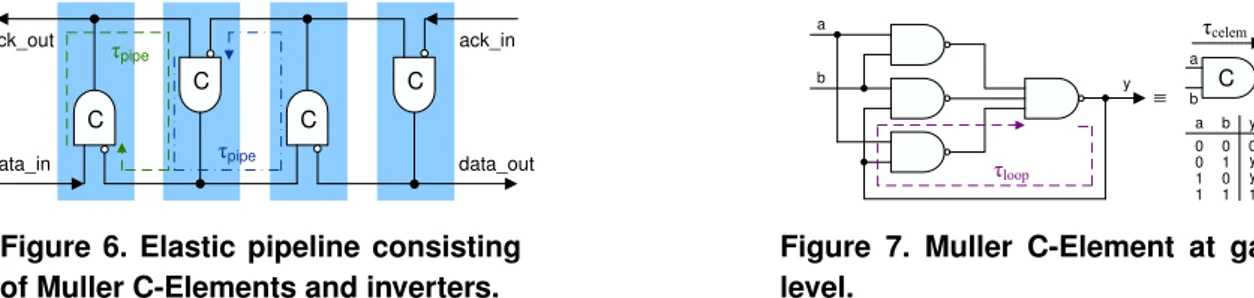
ack_in data_out data_in ack_out C C C C IJpipe IJpipe
Figure 6. Elastic pipeline consisting of Muller C-Elements and inverters.
C a b y IJloop b y a y IJcelem a b 0 1 0 0 1 1 0 1 yold 0 1yold Figure 7. Muller C-Element at gate-level.
The proof is by bounding the maximum time a tick messages can exist before it is eliminated by the Diff-Gate.
5 Hardware Implementation
Now we will present implementation details of the low-level building blocks of our TS-Alg implementation, which have been introduced at higher levels of abstraction in Fig. 3 and 4. We will also derive timing conditions an implementation has to satisfy in order to fulfill the behavioral specification of Section 3.2. It turns out, that the conditions can be enforced easily by design tools, if not a priori true.
5.1 Implementation of+/−Counters
Elastic Pipeline: An elastic pipeline can be seen as a FIFO buffer for signal transitions, based on Sutherland’s micropipelines [28]. As shown in Fig. 6, it consists of a chain of Muller C-Elements [21] (+ inverters), each of which can store a single low-to-high or high-to-low transition.
In order to get an idea of the internal operation of the elastic pipeline in Fig. 6, consider the gate-level imple-mentation of a Muller C-Element given in Fig. 7. It is apparent that it changes the value of its output y only if
both inputs have the same value – it hence implements an AND for signal transitions. Note that a C-Gate must incorporate a feedback loop, sinceymust stay at the current logic level when eitheraorb(but not both) changes.
The correct operation of the pipeline depends upon some timing constraints regarding (i) the feedback loop involved in the Muller C-Gates and (ii) the loop formed by two consecutive stages in the pipeline. Actually, the delays of those feedback loops impose some minimum delay between successive input transitions, which must be maintained in order not to jeopardize correct behavior. In standard delay-insensitive applications of elastic pipelines, this is ensured by triggering a newdata intransition only when theack outtransition that acknowl-edges the previousdata intransition occurs. Since we obviously cannot useack outin our application (we cannot acknowledge every generated clock tick), the required timing constraints must be externally maintained.
We will first analyze the timing conditions of the Muller C-Element: To allow the gates on the feedback path in Fig. 7 to settle, it has to be ensured thataand/orbdo not change state in opposite directions (high-to-low, low-to-high) withinτloop+ of each other. The conditionτmin ≥ τloop+ has to be obeyed for both consecutive transitions
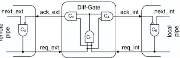
ack_ext ack_int req_ext req_int C3 C5 Diff-Gate C4 C2 C1 next_ext next_int re m ot e pi pe lo ca l pi pe
Figure 8. Diff-Gate in combination with remote and local pipeline
on a single input as well as opposite transitions on different inputs. However, different inputs can change state in the same direction arbitrarily close to each other, without affecting correct operation of the C-Element. The bound
τloop+ can be obtained by analyzing the netlist of the hardware generated by a synthesis resp. place&route tool.
The basic timing constraints for the elastic pipeline, which originate from the feedback loops formed by any two consecutive pipeline stages, as highlighted in Fig. 6, can be derived in a similar manner: As long as input signaldata indoes not change faster than any stage’sτpipe+ , i.e.,τmin ≥τpipe+ , no transition can be lost and the
elastic pipeline behaves as expected. Since activation of a C-Element’s output takes place after the propagation delay τcelem+ , cp. Fig. 7, we have τpipe+ = 2τcelem+ +τinverter+ +τwires+ . Ifτcelem+ is considered to be the same for
all C-Elements for simplicity, it follows that the minimum timing constraintτmin ≥ τloop+ for any single Muller
C-Element implicitly holds whenτmin≥τpipe+ andτpipe+ ≥τloop+ (place&route constraint).
It is important to mention, however, that the simple considerations above apply only to the case wheredata in
andack indo not change simultaneously. The latter case, which could obviously cause metastability problems if there were no additional constraints, is treated in conjunction with the Diff-Gate below.
Difference Gate: The Diff-Gate is responsible for removing matching transitions from the ends of the remote and local pipe, see Fig. 8. Our goal is to implement a+/−counter, which keeps track of the difference of the number of ticks seen so far. Still, every pipe must have at leastS =
¹
Tsim+max(τrem+,τloc+)+τDiff+
T−
f irst
º
+ 1stages to avoid
an overflow due to the fact that remote and local clock are not perfectly synchronized, cp. Theorem 4.13. Note that
Sis the only implementation-technology-dependent parameter that is compiled into the TS-Algs. However, since
it depends on the ratio of maximum and minimum delays only, like in the Theta-Model [16], rather than on the absolute delays, we are convinced that it is in fact reasonably independent from the implementation technology.
Our Diff-Gate implementation, which is basically an extension of the elastic pipelines by one stage and the matching of identical transitions by an additional Muller C-Element, is shown in Fig. 8. The inverter inC4reveals a
subtle but pivotal unsymmetry of our Diff-Gate: In case of matching values ofreq extandreq int, it removes the last transition of the remote (left) pipeline before it removes the matching last transition of the local (right) one. There are two reasons why this left-before-right removal is mandatory: The first one is related to guaranteeing the required properties of the signalsGEQe,GRe,GEQoandGRoand is explained in the context of the PCSG below. The second reason is the avoidance of metastability problems at C1 in Fig. 8, which connects two only loosely
coupled clock domains. To cause metastability problems, the inputs of the C-Element C1 have to change in a
manner (introduced earlier) where its internal τloop+ constraint is violated. We have shown before, however, that
this cannot happen in the standard case of a single input change if the pipeline constraint regardingτmin ≥ τpipe+
is maintained. Hence, we are left with the case where both inputs of C1 change in opposite directions within
τloop+ of each other. However, our Diff-Gate removes matching transitions only, i.e., acts only whenreq extand
req inthave the same value. Hence, after a matching 0, for example, any of the inputs, say,req extofC1
can go to 1 only whenack ext= 0 has been generated byC2and processed byC3. Hence,req extcan go to 1
not earlier than3τcelem− +τwires− > τloop+ (place&route constraint onτcelem− ofC1, C2, C3) after the last ofreq ext
andreq intwent to 0, andreq intcan not go to 1 before another2τcelem− + 2τinverter− +τwires− (τcelem− ofC4,
C5). Consequently, if the above constraint is maintained and if local and remote clock ticks are not generated
faster than they can be removed by the Diff-Gate, i.e., faster than τDiff− = 5τcelem− + 3τinverter− +τwires− ≥ τpipe+
(place&route constraint), we can ensure its correct operation. Since τDiff− is part ofD− cp. (4), which in turn
determines the minimum timeτmin between successive clock ticks according to Lemma 4.6, we can be sure that
τmin > τDiff− > τpipe+ > τloop+ . Hence, our+/−counters indeed work as expected.
Pipe Compare Signal Generators: The PCSG has to detect whether or not the remote pipeline holds the same or a greater number of transitions and must activate the corresponding status signals GEQe, GRe, GEQo and
GRo. Unlike all other building blocks described so far, the PCSG is not a transition signaling logic but rather a conventional asynchronous state logic. However, it must be able to handle transitions, which arrive at random instants, without producing glitches or wrongly activate its output signals. Since this is impossible in general, we have separatedGEQe,GRefromGEQoandGRo: As already explained in Section 2, the former signals are only relevant if the next tick to be generated is odd, whereas the latter status signals are only relevant when it is even. When the next tick to be generated is the other one, we do allow glitches and other incorrect signal changes.
To ensure correct behavior of our algorithm, the relevant status signals for the next tick to be generated, say,
GEQe, must be activated only if r
p,q(t) > rsp,q(t)∧sp,q(t) = 1 holds for sure. First of all, this requires a left-before-right removal of matching transitions by the Diff-Gate:GEQemust never become true, not even in a glitch, if the number of remote ticks seen is smaller than the number of local ticks. If we allowed the Diff-Gate to remove the right transition before the left one, however, the PCSG unit might see a larger number of remaining transitions in the remote pipe than in the local pipe, and would hence produce an erroneous output onGEQe. Second, it must be ensured that any state signal can become true only if the next tick to be generated is not already available in the local pipe. Note that this can happen for the pipelines corresponding to a slow remote node, where the faster ones have already achieved the required2f + 1orf + 1threshold. Our PCSG implementation ensures this by
comparing the last stages of the local and remote pipeline, subject to the condition that the three last stages of the local pipeline contain the same value. It is easy to see from the operation of an elastic pipeline that the latter condition signals an (almost) empty pipe, which is sufficient to infer the required “freshness” of the status outputs. 5.2 Other low-level building blocks
Apart from then−1 +/−counters, a TS-Alg also consists of standard asynchronousf+1and2f+1threshold
gates and a clock generation unit (represented by the OR-gate in Fig. 3).
Threshold gates:The threshold logic is responsible for implementing the if-clauses depicted in Fig. 5. The clock generation is based on four separate threshold gates: Two are active, waiting for≥f + 1GEQeresp.≥ 2f + 1
GRe, when the next tick to be generated is odd, while the remaining two, waiting for≥f+ 1GRoresp.≥2f+ 1
GEQo, are inactive, in the sense that they can behave arbitrarily.
Clock generation:According to the algorithm in Fig. 5, either the activef+ 1or the active2f+ 1threshold gate
may produce the next clock tick. Our implementation employs a suitable combination of high and active-low signals on the inputs and outputs of the threshold gates, which alactive-lows us to use a simple logical AND resp. OR for combining the two corresponding threshold gate outputs for generating even resp. odd ticks. The output of the odd and even tick generation is joined by a final Muller C-Element, which ensures that the local clock output remains stable until the next valid clock tick is generated. Note that this element can be seen as the back-transition from the state-based logic (PCSG and threshold gates) to transition signaling logic (+/−counters).
5.3 Experimental Evaluation
The low-level building blocks described above have been implemented using VHDL and assembled in a com-plete TS-Alg. We have also prototyped a comcom-plete system ofn= 5TS-Algs, which has been synthesized and put
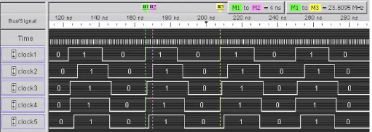
into operation on an Altera APEX EP20K1000 FPGA. The clock signals of all five TS-Algs in a sample run are depicted in Fig. 9. The clock frequency is approximately 24MHz, and the maximum skew of the clock ticks is 4ns. Of course, this FPGA implementation is just a proof of concept and shall demonstrate the principal feasibility of the DARTS approach. We are convinced that there is a huge potential for optimizations, e.g., to increase the clock frequency: FPGAs are not particularly suitable for asynchronous designs due to the structure of the lookup tables and registers. Furthermore, the performance of the TS-Alg clock depends upon the ratio of the routing delays of the longest and the shortest clock signal paths. Due to the static interconnect structure of an FPGA, these signal delays may vary within a wide range. We are hence convinced that much better performance, at much lower cost, can be obtained by the standard cell CMOS ASIC implementation ultimately targeted by our DARTS project.
Figure 9. DARTS approach with 5 TS-Alg running on an FPGA
6 Conclusions
We proposed a novel clock generation approach for VLSI chips that has been derived from a well-known dis-tributed fault-tolerant tick generation algorithm. It provides a set of local clock signals, to be fed to the subsystems of a SoC, for example, which are synchronized within a bounded precision to each other. Our approach does not need any external quartz oscillator or the like, and generates a clock frequency that automatically adapts to the current operating conditions.
Major modifications had to be applied to the original algorithm in order to adapt to the inherent fine-grain paral-lelism and limited resources of VLSI hardware implementations. Our algorithm depends upon the implementation technology only via the required numberS of stages of the elastic pipelines. SinceS depends upon the ratio of
maximum and minimum clock signal delays only, rather than on the delay values itself, we are convinced that it is actually reasonably independent from the implementation technology.
We also provided a correctness proof which shows that a system incorporatingn≥3f+2clock generation units
can cope with up tof Byzantine faulty nodes and links. This allows our algorithm to work correctly in presence
of up tof units that produce spurious clock transients perceived inconsistently by the other units. Our proof rests
upon simple properties of some locally available signals only, which can be verified by digital design tools. Hence, the correctness of a system of any sizencan be guaranteed if the low-level building blocks providing the required
signals are implemented correctly. Note that a comparable result cannot be established via model checking. Future work will be devoted to an ASIC implementation, optimization and a systematic experimental evaluation.
Acknowledgements
The contributions of Johann Vilanek (Diff-Gate, preliminary simulations and experiments), Markus Ferringer (FPGA implementation) and Thomas Handl (tools and library setup) are gratefully acknowledged. Valueable feedback on the design and implementation of our TS-Algs was provided by Josef Widder and Andreas Steininger, who also helped us to improve the presentation in this paper.
References
[1] A. Bar-Noy and D. Dolev. Consensus algorithms with one-bit messages.Distributed Computing, 4:105–110, 1991. [2] R. Bhamidipati, A. Zaidi, S. Makineni, K. Low, R. Chen, K.-Y. Liu, and J. Dalgrehn. Challenges and methodologies
for implementing high-performance network processors.Intel Technology Journal, 6(3):83–92, Aug. 2002.
[3] D. L. Black. On the existince of delay-insensitive fair arbiters: Trace theory and its limitations.Distributed Computing, 1:205–225, 1986.
[4] D. M. Chapiro.Globally-Asynchronous Locally-Synchronous Systems. PhD thesis, Stanford University, Oct. 1984. [5] C. Constantinescu. Impact of deep submicon technology on dependability of VLSI circuits. InProceedings of the
International Conference on Dependable Systems and Networks (DSN’02), pages 205–209, June 2002.
[6] D. Dolev, J. Y. Halpern, and H. R. Strong. On the possibility and impossibility of achieving clock synchronization. Journal of Computer and System Sciences, 32:230–250, 1986.
[7] E. M. C. (ed.). Editorial: Distributed computing issue in hardware design.Distributed Computing, 1:185–186, 1986. [8] S. Fairbanks and S. Moore. Self-timed circuitry for global clocking. InProceedings of the Eleventh International IEEE
Symposium on Advanced Research in Asynchronous Circuits and Systems, pages 86–96, Mar. 2005.
[9] E. G. Friedman. Clock distribution networks in synchronous digital integrated circuits. Proceedings of the IEEE, 89(5):665–692, May 2001.
[10] S. Hauck. Asynchronous design methodologies: An overview.Proceedings of the IEEE, 83(1):69–93, Jan. 1995. [11] K. Hoyme and K. Driscoll. Safebus. InProceedings IEEE/AIAA 11th Digital Avionics Systems Conference, pages
68–73, 1992.
[12] International technology roadmap for semiconductors, 2001.
[13] R. M. Kieckhafer, C. J. Walter, A. M. Finn, and P. M. Thambidurai. The MAFT architecture for distributed fault tolerance. IEEE Transactions on Computers, 37:398–405, Apr. 1988.
[14] H. Kopetz and G. Gr¨unsteidl. TTP-A protocol for fault-tolerant real-time systems. Computer, 27(1):14–23, 1994. [15] L. Lamport. Time, clocks, and the ordering of events in a distributed system. Commun. ACM, 21(7):558–565, 1978. [16] G. Le Lann and U. Schmid. How to implement a timer-free perfect failure detector in partially synchronous systems.
Technical Report 183/1-127, Department of Automation, Technische Universit¨at Wien, January 2003.
[17] A. Maheshwari, I. Koren, and W. Burleson. Accurate estimation of Soft Error Rate (SER) in VLSI circuits. In Proceed-ings of the 2004 IEEE Int. Symposium on Defect and Fault Tolerance in VLSI Systems, pages 377–385, Oct. 2004. [18] A. J. Martin. Compiling communicating processes into delay-insensitive VLSI circuits.Distributed Computing, 1:226–
234, 1986.
[19] M. S. Maza and M. L. Aranda. Analysis of clock distribution networks in the presence of crosstalk and groundbounce. InProceedings International IEEE Conference on Electronics, Circuits, and Systems (ICECS), pages 773–776, 2001. [20] M. S. Maza and M. L. Aranda. Interconnected rings and oscillators as gigahertz clock distribution nets. InGLSVLSI
’03: Proceedings of the 13th ACM Great Lakes symposium on VLSI, pages 41–44. ACM Press, 2003. [21] R. E. Miller. Sequential Circuits and Machines, volume 2 ofSwitching Theory. wiley, 1965.
[22] S. Mitra, N. Seifert, M. Zhang, Q. Shi, and K. S. Kim. Robust system design with built-in soft-error resilience. IEEE Computer, 38(5):43–52, Feb. 2005.
[23] A. K. Palit, V. Meyer, W. Anheier, and J. Schloeffel. Modeling and analysis of crosstalk coupling effect on the victim interconnect using the ABCD network model. InProceedings of the 19th IEEE International Symposium on Defect and Fault Tolerance in VLSI Systems (DFT’04), pages 174–182, Oct. 2004.
[24] U. Schmid. How to model link failures: A perception-based fault model. InProceedings of the International Conference on Dependable Systems and Networks (DSN’01), pages 57–66, G¨oteborg, Sweden, July 1–4, 2001.
[25] U. Schmid, J. Klasek, T. Mandl, H. Nachtnebel, G. R. Cadek, and N. Ker¨o. A Network Time Interface M-Module for distributing GPS-time over LANs. J. Real-Time Systems, 18(1):24–57, Jan. 2000.
[26] U. Schmid and A. Steininger. Dezentrale Fehlertolerante Taktgenerierung in VLSI Chips. Research Report 69/2004, Technische Universit¨at Wien, Institut f¨ur Technische Informatik, 2004. ( ¨Osterr. Patentanmeldung A 1223/2004). [27] T. K. Srikanth and S. Toueg. Optimal clock synchronization.Journal of the ACM, 34(3):626–645, July 1987.
[28] I. E. Sutherland. Micropipelines.Communications of the ACM, Turing Award, 32(6):720–738, JUN 1989. ISSN:0001-0782.
[29] J. Widder. Distributed Computing in the Presence of Bounded Asynchrony. PhD thesis, Vienna University of Technol-ogy, Fakult¨at f¨ur Informatik, May 2004.