GLOBE/ANGLE
CAGE-GUIDED
KOSO KENT INTROL
SUPPLIES A DIVERSE
RANGE OF PRECISION
-MANUFACTURED
CONTROL, CHOKE,
AND ROTARY VALVES
FOR OIL AND GAS,
PETROCHEMICAL AND
POWER INDUSTRIES
– WORLDWIDE
PRODUCT SERIES 1200 & 7200 TABLE OF CONTENTS – TRIM OPTIONS 04– LIQUID SERVICE TRIM SELECTION 05
– VECTOR SEVERE SERVICE TRIMS 09
– SELECTION GUIDELINES 10
PRODUCT
RANGE
---TOP & BOTTOM-GUIDED CONTROL VALVES
Our range of high-performance top and bottom-guided control valves includes single and double-seated valves suitable for low and high-capacity applications, as well as three-way valves for mixing or splitting flows. Our control valves are designed to facilitate pressure drops at all stages of transportation in the oil, gas and power industries. All valves are refined by our engineers to suit the needs of each application and all service conditions. CAGE-GUIDED CONTROL VALVES
The Series 1200/7200 range of cage-guided control valves is KKI’s core product. The exceptional valves in this range combine high-integrity features, such as ASME VIII
body/bonnet bolting design, a high flow capacity and a wide range of trim designs, from low-noise anti-cavitation to multi-stage trims. These valves are ideally suited to the critical service process control requirements of a wide range of industry applications.
SURFACE CHOKE VALVES
The KKI Series 73 surface choke valve offers a unique solution for the majority of choke applications in the oil and gas industry. The flexible valve design can incorporate many different trim and body material options to suit differing flow rates and in-service conditions. Thousands of KKI Series 73 surface chokes are installed around the world on projects for some of the world’s leading oil and gas production companies. ROTARY CONTROL VALVES
The Rotrol range of high-capacity butterfly valves has been developed to overcome the problems associated with control, cavitation and noise in conventional butterfly valve designs. Lighter in weight and more compact than globe valve alternatives, this innovative valve performs especially well in severe-service applications, where pressure drops tend to be high in the controlling position but where high-capacity throughputs at low pressure drops are also required.
SEVERE SERVICE SOLUTIONS
For more than 45 years, KKI has built up a reputation for delivering valve solutions for the most arduous service conditions. We have developed a range of advanced, high-quality severe service valve solutions for every type of problematic application, from high-pressure, high-temperature environments to sub-zero temperatures. Our valves are designed to combat the effects of cavitation, flashing, erosion, contaminated fluids, corrosion, high velocity, vibration, noise and energy dissipation. INSTRUMENTS
KKI offers a wide selection of sophisticated instrumentation to support our comprehensive range of high-performance valves and actuators. The instruments we supply include pneumatic and electro-magnetic positioners, airsets, volume boosters and airlocks. All instruments are specified to deliver optimum performance for the service conditions and specific needs of each application. We also supply proprietary instruments to suit individual customer preferences.
ACTUATORS
Our range of robust, versatile and reliable pneumatic actuators includes the ‘G’, ‘C’ and ‘D’ Series models. These have been developed to meet the needs of all control valve applications, offering proven design and high reliability. They are used extensively for on-shore, offshore and power installations. In addition, we supply various proprietary actuators – such as electric, electro-hydraulic, pneumatic stepping and hydraulic stepping actuators – to meet customer requirements. All actuators can be supplied with hand-wheels and limit stop features.
TOP & BOTTOM-GUIDED CONTROL VALVES
SINGLE SEATED SERIES 10/71 DOUBLE SEATED SERIES 20 3-WAY MIXING AND DIVERTING SERIES 30
SURFACE CHOKE VALVES ROTARY CONTROL VALVES
INSTRUMENTS
ACTUATORS
SERIES 73 SERIES 60
SERIES C SERIES D
SERIES G
SEVERE SERVICE SOLUTIONS CAGE-GUIDED CONTROL VALVES
CAGE-GUIDED VALVES
Kent Introl’s Series 1200/7200 range of control valves have long been established in the oil and gas, power and petrochemical market. This is KKI’s main globe/angle product suitable for operation over a wide range of applications and operating conditions.
This range of valves combines high-integrity features, such as ASME VIII body/bonnet bolting design, a high flow capacity and a wide range of trim designs. This means it is ideally suited to meet the various critical service process control requirements that are demanded by a wide range of industry-related applications.
The Series 7200 is the angle version of the Series 1200, incorporating identical trim and options.
PERFORMANCE:
– Noise, cavitation control and erosion resistant trims. – Streamlined flow passages to optimise capacity. – Stable flow control with high rangeability.
DESIGN FLEXIBILITY:
– Modular construction design available with a range of different end connections and styles.
– Large variation of trim designs from single stage drilled cage to multiple stage low noise/anti-cavitation trim designs. – Wide range of supplementary noise control components, silencers, dynamic attenuators.
– Inherently characterised trim offered in equal percentage, modified Eq%, linear and quick open. – Balanced or unbalanced plug designs.
– All trim components removable from the top for ease of maintenance and quick replacement. – Clamped in guide for ease of service.
– Large range of CVs per body size allowing for large changes in process conditions.
DESIGN INTEGRITY:
– High-integrity body/bonnet bolting system designed to ASME VIII. – Clamped cage for positive guiding on severe service applications. – High-integrity plug guiding system.
– Low emission packings i.e. (ISO 15878).
QUALITY-ASSURED MANUFACTURING:
– Rigorously tested to ensure specified performance on site. – Quality-assurance systems in accordance with ISO 9001. – Optional full ISO 15156/NACE MR-01-75 certification.
PRODUCT SERIES 1200 & 7200
03
SCOPE OF DESIGN
VALVE BODY/END CONNECTION SIZES – 1” to 36” (25mm to 900mm) nominal bore. VALVE BODY RATINGS
– ANSI 150 to ANSI 4500 (PN10 to PN640). – API ratings can also be supplied. DESIGN STANDARDS
– ASME B16.34. – ASME VIII.
– ASME FCI 70-2 control valve seat. LEAKAGE
– ASME B16.25 – butt weld end valves
– ASME B16.5 – pipe flanges and flange fittings – NACE MR-01-75/ ISO 15156
– Designs fully PED certified. TRIM DESIGNS
There are a large range of trim designs to cover the wide range of applications encountered in the served industries. The standard design is a low noise/anti-cavitation trim referred to as an HF (High Friction) trim. This is complemented by several multi-stage designs with up to nine stages (20 turns) of let down. These are described in detail within this bulletin. A labyrinth trim design, Vector, can also be designed and fitted into the S1200/S7200 body.
PLUG DESIGNS – Balanced. – Solid.
– Pilot balanced. BODY MATERIALS
The Series 1200 range can be supplied in the majority of castable alloys as required by the service. All materials used are fully PED certified. Standard materials include: – Carbon steel – WCB/LCB/LCC.
– Stainless steel – CF8M, CF3M etc. – Chrome moly – WC6, WC9.
– Duplex st. st – A995 Gr 4A/5A/6A, A351-CK- 3MCUN etc. – High alloys – Monel, Hastelloy B/C, Alloy 625, Alloy 825. – Aluminium bronze.
– Titanium.
Offset globe/angle valves are also available in forged and HIPed materials.
TRIM MATERIALS
All materials compatible with the above body materials are given later in this document. Stellite overlays and tungsten carbide inserts will be specified for high pressure drop and low/high temperature applications, or where there are significant levels of contamination.
BONNET OPTIONS
– Standard/normalising/cryogenic. – Bolted/clamped/pressure seal. ACTUATION
The standard actuation offered is a spring return diaphragm actuator. For more arduous duties, where high operating forces are encountered, piston spring return and double-acting would be specified.
In addition, most other third-party actuators can be fitted, i.e. electric, electro-hydraulic, etc.
– ‘G’ Series spring-opposed pneumatic diaphragm. – ‘C’ Series spring-opposed pneumatic piston. – ‘D’ Series double-acting piston.
– Most third-party actuators.
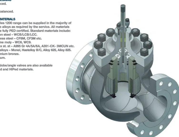
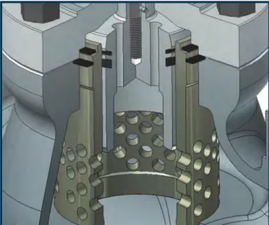
FIGURE 1. SERIES 1200 FITTED WITH THREE-STAGE (FIVE TURN) TRIM
GENERAL DESCRIPTION
Figure 2 shows the general features of the S1200 fitted with HF trim design. The cage is clamped between the body bridge and the bolted bonnet, and the primary seal is either a spiral wound gasket or a metallic seal (ANSI 2500 to ANSI 4500). The guide (cage) is located within the valve body by its upper and lower sections to give the best possible support and to ensure concentricity between the body/bonnet and trim components. The lower part of the cage is drilled with a number of radial holes, over the length of the plug travel. In Figure 2, the plug is shown in its fully open position. The flow is controlled by the plug moving up or down within the cage covering and uncovering holes to vary the flow area and consequently the flow through the valve. The plug is designed to be guided within the cage, therefore clearances between the cage and plug are critical. In order to ensure there is no galling (pick-up) between the plug and cage, the cage is either hard chrome plated or the plug/cage stellited. Stellite running on stellite has excellent galling resistance. On high temperature/power applications, hardened materials 420 st. st. and 17/4 PH st. st. are utilised. Again these materials have excellent galling resistance.
On high duty applications the plug/cage clearance will be designed around the specified design temperature, and a guide/damping strip may be included to give enhanced stability. One of the common features of the various trims in a Series 1200/7200 valve is the use of a balanced plug design. This significantly reduces the resultant unbalanced forces acting on the valve plug. This is achieved by allowing the same process pressure (either the inlet pressure when the flow is ‘under’ the plug or the outlet pressure when the flow is ‘over’ the plug) to act equally above and below the plug. The holes shown on the top of the plug pass through into the lower section of the plug, enabling the pressure above and below the plug to equalise. The net effect is that unbalanced force in the open position is equal to only the stem area multiplied by the pressure. In order to ensure that this is not a leak path when the valve is in the closed position, the plug is fitted with a plug seal, preventing axial flow between the plug and cage.
HF – HIGH FRICTION TRIM
First introduced in 1969, the HF (High Friction) trim is suitable for the majority of process control applications. It is a low pressure recovery design which gives both advantageous cavitation reduction and noise reduction when compared with standard profiled trim designs. The flow can be directed either ‘under’ the plug (the flow passes through the seat into the inside of the cage and then through the radial holes to outside the cage), or ‘over’ the plug (the flow passes from the outside of the cage, through the radial holes, to the inside of the cage and then down through the seat into the valve outlet). The flow direction varies depending on the process fluid. For liquid, flows ‘over’ the plug are preferred. In this case the flow is split into many radial jets and as the flow passes through the cage the jets impinge upon themselves within the confines of the cage. This is where most of the flow energy is
dissipated, and the erosional forces will be at their highest. The flow then exits the trim through the valve seat. This means the valve body is protected from the effects of flow erosion. A trim manufactured from harder materials is more capable of handling these erosional forces. On the more severe
applications, high pressure drop, contaminated fluids etc, the trim’s operational life can be maintained by using overlays such as stellite or tungsten carbide inserts.
On gas/vapour services, the preferred flow direction is ‘under’ the plug. The main reason for this is that it has been shown that the acoustic efficiency is lower in this direction. This reduction is attributed to the smaller scale turbulence
structure and higher frequency of the flow turbulence resulting in a greater level of attenuation from the downstream
pipework, which results in a lower transmitted noise on HF designs. On the HF family of trims, noise reduction of between 15 to 20dBA can be achieved over a conventional
contoured/ported trim. In cases where further noise reduction is required, smaller holes, i.e. 3mm/4mm can be utilised in the cage. This can result in further attenuation between 3 to 10dBA. FIGURE 2. SERIES 1200 HF TRIM DESIGN
PRODUCT SERIES 1200 & 7200
05
FOR FLASHING SERVICE/CONTAMINATED SERVICE
Over 30 years of supplying valves into the oil and gas retrieval industry have resulted in KKI gaining a great depth of knowledge in providing solutions for arduous service applications.
There is no hard and fast rule for identifying a severe service application. However, we may assume the following as potentially severe liquid services:
– Pressure drop >50bar (700psi).
– Flashing services P2 - Pv >30bar (435psi). – Multi-phase P1 - P2 >30bar.
– Contaminated service.
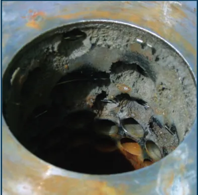
KKI has supplied many valves on these types of application and from experience identified that on flashing, multi-phase and contaminated services there can be detrimental performance if multi-stage trim designs are mis-specified. The photographs in Figure 3 give evidence of the erosion damage that can occur in supplying multi-stage trim designs on flashing and/or contaminated services.
FIGURE 3. MULTI-STAGE TRIM – EROSION DAMAGE
LIQUID SERVICE TRIM
SELECTION
The reason for the accelerated wear in these cases is attributed to high inter-stage flow velocities. This will occur on flashing service or multi-phase flows as soon as the pressure is reduced below the fluid vapour pressure or entrained gas is released. This results in a significant increase in the specific volume of the fluid leading to much higher flow velocities and greater erosional forces. In recognising this problem, KKI has been able to solve many erosion problems by changing out labyrinth
type/multi-stage trims to a single stage of pressure let down incorporating tungsten carbide inserts. The success of this approach resulted in the launch of the choke valve product range during the 1980s, a product that has gained an excellent reputation.
FIGURE 4. SELECTION OF TRIM ON CONTAMINATED SERVICES FIGURE 5. TRIM INCORPORATING SOLID TUNGSTEN CARBIDE INSERT 100 10 1 % CONTAMINATION BY WEIGHT 0 0001 001 01 1 1 10 P R E S S U R E D R O P ( B A R )
NO. PART NAME STD MATERIAL
1 Upper guide 17/4 Ph st. st
2 Lower guide 17/4 Ph st. st
3 Lower guide Tungsten carbide
carbide insert incorporating seat
4 Plug stem 17/4 Ph st. st
5 Carbide plug head Tungsten carbide 6 Upper plug retainer 17/4 Ph st. st 7 Lower plug retainer 17/4 Ph st. st
1 1 2 3 4 2 3 4 5 6 7 1 Base material
2 Base material + stellite face 3 Base material + full face 4 Tungsten carbide or ceramic
TUNGSTEN CARBIDE TRIM DESIGN
Figure 5 illustrates a carbide trim design. This has been developed over many years with essential design criteria, interferences etc, critical to the correct operation of the valve. There are also various grades of tungsten carbide which are selected around the specific design and depend on the process fluid being controlled.
The carbide cage is retained within a metallic cartridge (‘brickstopper’) protecting it against impact from large debris. Figure 5 illustrates a standard control valve seat design. However, KKI also uses a patented seating design on contaminated services. This design is known as an LCV trim, the name taken from the application it was first used on. The LCV design keeps the throttling components away from the high-velocity erosive zones by directing the flow to specific sacrificial energy-dissipating elements. The trim can be provided with or without a sacrificial plug nose.
SEAT EXIT DIFFUSER
It is recommended practice to specify angle valve design on high-pressure drop flashing/contaminated services. However, if the installation requires a globe design then KKI
recommends the use of a seat exit diffuser. The diffuser is used to prevent the high velocity fluid exiting the trim from impinging directly onto the body wall. The diffuser handles the initial impact of the process fluid and then breaks the fluid flow into small jets directed towards the valve outlet. The diffuser is normally manufactured from hardened materials or stellite overlayed
stainless steel to reduce the rate of erosion. Figure 4 gives an indication of the trim material overlay/insert
requirements based on the operating pressure drop and the level of contamination. Other factors that will influence the correct material selection are flashing or the level of entrained gas that will come out of solution as the process pressure reduces.
PRODUCT SERIES 1200 & 7200
07
MULTI-STAGE GUIDES, HFD, HFT & HFL
The multi-stage guides, HFD (High Friction Double), HFT (High Friction Triple) are a design enhancement on the standard HF trim. They are used in applications where noise or cavitation would otherwise be a problem. If not properly controlled, high pressure drop liquid applications can severely damage the valve. Figure 6 shows a cage that has suffered from severe cavitation damage. It should be noted that this mechanism can occur on relatively low pressure drops with the more conventional trims, for example contoured, ported trim designs.
In order to avoid the destructive effects of cavitation, it is necessary to apportion the pressure drop across a number of stages of let down. There are two different families of trims that can be applied to this problem, as well as the Series 50/57 specialist anti-cavitation trim design and Vector (labyrinth). The HFD (two stages) and HFT (three stages) apportion the pressure drop equally across either two or three stages of let down. The stages are in the form of concentric sleeves, drilled with radial holes within a number of grooves that form distinct flow galleries. These will be specified on the less severe applications.
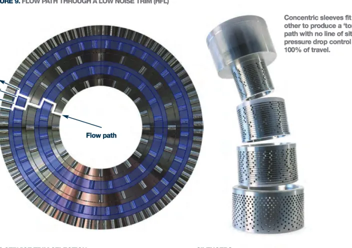
The HFL design, illustrated in Figure 7, also incorporates a number of concentric sleeves (two or more). Each sleeve has a multitude of grooves incorporating radial holes. The grooves in each sleeve line up to create a torturous radial flow path (see Figure 9). The trim uses the principle of controlled trim exit velocity. The holes within the sleeves are completely misaligned to produce a tortuous path through the trim. Energy is dissipated within the cage by the combined effect of flow splitting, flow impingement, and turning of the flow as it passes through the sleeves. There is a large increase in flow area between the stages of let down resulting in a reduction in pressure drop as the flow passes from one stage to the next.
This significantly reduces the likelihood of cavitation, because the final stage of let down has a relatively small pressure drop and, with its low recovery characteristic, this minimises the potential for cavitation. Figure 8 represents the difference between a single stage high-recovery trim, and a three-stage trim with equal stage pressure drop, e.g. the HFL3 design.
FIGURE 6. CAVITATION DAMAGE
FIGURE 7. HFL-3 TRIM DESIGN
P1 PV P2 P1VC Stage 1 Stage 2
Valve inlet
Valve outlet
Stage 3
CAVITATING FLOW FIGURE 8. STAGE PRESSURE DROP
VENA OUTLET
HFL-3 stage pressure drop
FIGURE 9. FLOW PATH THROUGH A LOW NOISE TRIM (HFL)
Flow path
GAS SERVICE TRIM SELECTION
The major factors to be considered in the selection of a valve trim on a gas/vapour service are aerodynamic noise generation, vibration, and high fluid velocities. Each of these are interrelated in that high velocities can lead to vibration and resultant noise, and will also generate aerodynamic noise. It is therefore necessary to control the fluid velocity through the stages of let down in the trim and also in the valve outlet and downstream pipework. Poor installation of pipework, such as bends immediately before and/or after the valve can also be a major factor in the valve functioning correctly.
KKI undertook an extensive research programme during the 1980s into aerodynamic noise generation within control valves. This resulted in the successful introduction of low-noise trim designs referred to as HFQ1 and HFQ2. These complemented the already proven HFD and HFT trim designs that had been previously used for low-noise applications. The trims work in a similar principle to the liquid service designs, in that they split the flow up into a large number of radial jets, see Figure 9. The preferred flow direction is ‘under’ the plug, this enables the optimum flow area increase as the flow passes through each stage of the trim. The result is a very low trim exit velocity and very high levels of noise attenuation.
The flow geometry means that the process fluid enters the cage radially and passes through the subsequent sleeves in a tortuous path resulting in high frictional and impingement losses. Shock wave formation is controlled by jet impingement onto the sleeves, which has been shown to have a major (advantageous) bearing on the noise generation process. The HFL trim as discussed on the previous page and depicted above incorporates the highest level of attenuation, and is specified on the most arduous duties
SILENCERS
In solving the aerodynamic noise generation problem it must also be recognised that there is a need to control downstream velocities, otherwise high pipeline velocities can produce secondary noise which could be significantly higher than that produced by the valve trim. It is generally accepted that to achieve a low-noise solution, the downstream velocity should be restricted to less than 0.3 times the fluid sonic velocity. This coincides with the velocity at which compressibility effects start to become noticeable. In order to address this problem, KKI utilises downstream silencers in the form of a taper pipe fitted with a number of baffle plates (circular plates with a number of drilled holes). These are used to produce a back-pressure to the valve and are selected so that the velocity from the trim exit to the valve outlet is less than 0.3 times sonic velocity (0.3 Mach). In selecting these devices it is necessary to ensure that the trim and silencer system operate effectively over the full range of operating conditions. This approach has effectively been used by KKI for more than 30 years. A large number of these units are installed in the oil and gas and power sectors.
VARIABLE STAGE GUIDE
The variable stage guide is used on applications where multiple stages of pressure let down are required, but a high trim capacity is desirable. The trim is therefore constructed with multiple stages of pressure let down at lower travels, but typically is a single stage trim at higher travels. This design is suitable for controlling high pressure drops at low flow rates and a reduced pressure drop at normal or maximum flow rate. The number of stages of pressure let down and the actual transition between the multiple and single guides is dependent on the process conditions, so each variable stage guide tends to be designed specifically for the application.
Concentric sleeves fit over each other to produce a ‘tortuous’ path with no line of site and pressure drop control through 100% of travel.
PRODUCT SERIES 1200 & 7200
09
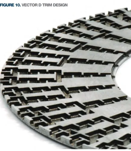
KKI is now in the position to supply the KOSO Vector trims. These trims extend the capability of KKI to offer trim designs for the most severe operating conditions now found in the various industries we serve. KKI is in the enviable position of being able to supply the most appropriate design for the specified application whether high pressure drop cavitating, high pressure drop flashing or high pressure drop gas applications. This proven trim design delivers accurate control, and long life, free from cavitation, erosion, vibration and noise problems. The design has evolved through many decades of experience in solving severe service applications where durability, reliability, repeatability and control precision are required. The advanced design velocity control trim prevents generation of noise and/or cavitation at the source. The typical applications for which the KOSO Vector trim has been applied also include compressor recycle and turbine by-pass. KOSO Vector trim limits harmful flow velocities by separating the flow into smaller individual channels, and staging the full pressure drop across multiple turns in the fluid path. This is the basic principle of the HFL trim designs, however, on the Vector designs the allowed pressure drops are significantly lower, leading to much lower velocities that are well within any threshold for erosion for the majority of trim materials.
As well as the Vector D trim shown in Figure 10. KOSO has also developed Vector M trim, shown in Figure 11. This gives a smooth and continuous increasing flow along the entire stroke length. This eliminates the inherent stepped flow that occurs in most stacked disc designs, see Figure 12.
VECTOR
TM
SEVERE
SERVICE TRIMS
FIGURE 10. VECTOR D TRIM DESIGN
FIGURE 11. VECTOR M TRIM DESIGN FIGURE 12. FLOW CHARACTERISTIC COMPARISON
SELECTION GUIDELINES
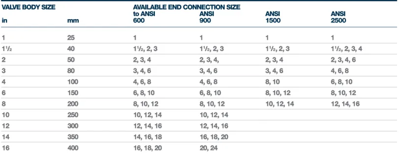
The following tables are used during the selection process of the valve. Design Cv values are incorporated in globe/angle cage-guided valves technical data. Flanges are specified as a nominal size, the actual bore size varies with pressure class. On higher rated flanges, the flange bore can be considerably less than the body bore area. This could lead to the flange end connection restricting the capacity of the valve. In order to ensure this does not happen, the following tables reference the end sizes available as a function of valve body size and pressure rating.
VALVE BODY SIZE AVAILABLE END CONNECTION SIZE
to ANSI ANSI ANSI ANSI
in mm 600 900 1500 2500 1 25 1 1 1 1 11/ 2 40 11/2 11/2, 2, 11/2, 2, 3 2, 3 2 50 2 2, 3, 2, 3, 4 3, 4 3 80 3 3, 4, 3, 4, 6 4, 6 4 100 4 4, 6, 6, 8 6, 8 6 150 6 6, 8, 8, 10 8, 10 8 200 8 8, 10, 10, 12 12, 14 10 250 10 10, 12, 12, 14 14, 16 12 300 12 12, 14, 14, 16 18, 20 14 350 14 16, 18, 16, 18 16 400 16 18, 20, 20, 24 18 450 18 20 500 20 24 600 24
TABLE 13. FLANGED END RESTRICTIONS
VALVE BODY SIZE AVAILABLE END CONNECTION SIZE
to ANSI ANSI ANSI ANSI
in mm 600 900 1500 2500 1 25 1 1 1 1 11/ 2 40 11/2, 2, 3 11/2, 2, 3 11/2, 2, 3 11/2, 2, 3, 4 2 50 2, 3, 4 2, 3, 4, 2, 3, 4 2, 3, 4, 6 3 80 3, 4, 6 3, 4, 6 3, 4, 6 4, 6, 8 4 100 4, 6, 8 4, 6, 8 8, 10 6, 8, 10 6 150 6, 8, 10 6, 8, 10 8, 10, 12 8, 10, 12 8 200 8, 10, 12 8, 10, 12 10, 12, 14 12, 14, 16 10 250 10, 12, 14 10, 12, 14 12 300 12, 14, 16 12, 14, 16 14 350 14, 16, 18 16, 18, 20 16 400 16, 18, 20 20, 24
PRODUCT SERIES 1200 & 7200
11
LIQUIDS GASES/VAPOURS
MAX
∆
P MAX∆
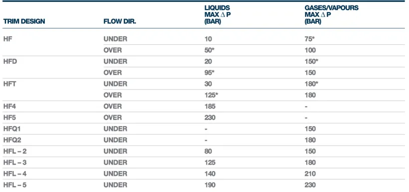
PTRIM DESIGN FLOW DIR. (BAR) (BAR)
HF UNDER 10 75* OVER 50* 100 HFD UNDER 20 150* OVER 95* 150 HFT UNDER 30 180* OVER 125* 180 HF4 OVER 185 -HF5 OVER 230 -HFQ1 UNDER - 150 HFQ2 UNDER - 180 HFL – 2 UNDER 80 150 HFL – 3 UNDER 125 180 HFL – 4 UNDER 140 210 HFL – 5 UNDER 190 230
TABLE 16. PRESSURE DROP LIMITATIONS
NOTE: * Not suitable for oxidizing service. The Envirograph range of packings, Envirograph 4 to 6 area used for low emission requirements and a graphite based packing system.
NOTE: 1. Pressure drop limits do not apply to flashing applications.
2.These apply on the basis that cavitation has been eliminated.
3.In cases of wet/saturated vapours then pressure drops for liquids should be applied.
4.On liquid applications, where final stage pressure drops are greater than 50bar, angle valves are recommended. 5. VECTORTM velocity control labyrinth multi-turn disk stack trim is available for high pressure drop applications.
* These are the recommended flow directions for these trims.
BELOW -100OC -100OC TO -29OC -29OC TO -250OC -250OC TO -400OC ABOVE 400OC
COMPONENT (-150OF) (-148OF TO -4OF) (-4OF TO 482OF) (482OF TO 752OF) (752OF)
BONNET CRYOGENIC NORMALISING STANDARD NORMALISING NORMALISING
PACKINGS PTFE CHEVRON PTFE CHEVRON PTFE CHEVRON GRAPHITE(*) GRAPHITE(*) TABLE 15. BONNET/PACKAGING OPTIONS
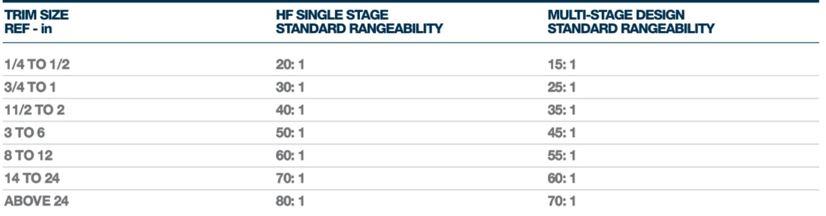
TRIM SIZE HF SINGLE STAGE MULTI-STAGE DESIGN
REF - in STANDARD RANGEABILITY STANDARD RANGEABILITY
1/4 TO 1/2 20: 1 15: 1 3/4 TO 1 30: 1 25: 1 11/2 TO 2 40: 1 35: 1 3 TO 6 50: 1 45: 1 8 TO 12 60: 1 55: 1 14 TO 24 70: 1 60: 1 ABOVE 24 80: 1 70: 1
TABLE 17. STANDARD RANGEABILITY VALVES
INLET OUTLET
VALVE SIZE REQ. NOISE LEVEL dBA ft/s m/s ft/s m/s MACH NUMBER
ALL > 95 670 204 1150 350 0.65
ALL < 95 670 204 1150 350 0.5
1/2" TO 2" < 85 670 204 1150 350 0.4 3" TO 24" < 85 670 204 1150 350 0.3 TABLE 24. SERIES 1200 & 7200 GAS VAPOUR VELOCITY LIMITS
NOTE: Rangeability is the relationship between the minimum controllable Cv and the design Cv of the trim.
NOTE: Use velocity limit as higher of linear velocity or Mach numbers.
CONTROL VALVES USED ON VENT TO FLARE APPLICATIONS
PRODUCT SERIES 1200 & 7200
13
PLUG DESIGN SEATING STYLE PISTON RING LEAKAGE CLASS TEMPERATURE RANGE
Unbalanced Metal/metal None III, IV &V Cryogenic to 565oC
Unbalanced Metal/soft face None VI Cryogenic to 315oC
Balanced Metal/metal Graphite III 250oC to 565oC
Balanced Metal/metal Carbon/PTFE IV & V Cryogenic to 265oC
Balanced Metal/metal Alloy 25 IV 265oC to 565oC
Pilot balanced Metal/metal Carbon V 265oC to 565oC
Balanced Metal/soft face Carbon/PTFE VI* Cryogenic to 265oC
TABLE 19. LEAKAGE CLASS OPTIONS
NOTE: For contaminated services a scraper will be incorporated within the plug seal. * This is a special design for valve sizes upto 10” (250mm) – the application must be reviewed by Applications before specifying.
INDUSTRY TYPICAL DUTIES GUIDE PLUG STEM SEAT TEMP
SECTOR RANGE
OIL Standard 316 st. st. + hard 316 st. st. 316 st. st. Integral with guide/ -40OC to 250OC
& GAS combination/NACE chrome plated or or 17-4PH st. st. 316 st. st.
17/4 PH St.St.
Sea water/sour gas Duplex + hard Duplex Duplex Integral with guide/ -40OC to 250OC
chrome plated Duplex st. st.
Sea water/sour gas Super Duplex + Super Duplex Super Duplex Integral with guide/ -40OC to 250OC
hard chrome Super Duplex st. st.
plated
Highly corrosive Monel K500 Monel 400 Monel K500 Integral with guide/ -40OC to 250OC
hardened Monel K 500;
Highly corrosive Hastelloy (B/C) + Hastelloy (B/C) Hastelloy (B/C) Integral with guide/ -40OC to 250OC
hard chrome plated Hastelloy (B/C)
Highly corrosive Alloy 625 + hard Alloy 625 Alloy 625 Integral with guide/ -40OC to 250OC
chrome plated alloy 625
Highly corrosive Titanium/titanium Titanium Titanium Integral with guide/ -40OC to 250OC
nitride titanium
Low temp Hard chrome plate Gr. 6 Stellite - - -100OC to 250OC
Cryogenic Gr. 6 Stellite Gr. 6 Stellite - - <-100OC
Medium temp Hard chrome plate Gr. 6 Stellite - - 250OC to 350OC
High temp Gr. 6 Stellite Gr. 6 Stellite - - 350OC to 400OC
Fast stroking time i.e Gr. 6 Stellite Gr. 6 Stellite - -
-compressor recycle > 1.75” (45mm)/sec
Liquids – pressure - Gr. 6 Stellite - Gr. 6 Stellite
-drops 20 - 35bar (300 - 500psi)
Liquids – pressure Gr. 6 Stellite Gr. 6 Stellite - Gr. 6 Stellite -drops 35bar
(500psi)
Liquids – pressure Tungsten carbide Tungsten carbide - Tungsten carbide
-drops > 150bar insert insert insert
(2175psi)
Contaminated Tungsten carbide Tungsten carbide - Tungsten carbide
-services insert insert insert
POWER Feadwater 420 St. St 420 St.St. Rc 35- 431 st. st. Integral with guide/ <250OC
hardened 43 or 17-4PH St.St. 316 St.St.+Colmonoy Rc 39-41
Low temp steam 420 St. St 420 St.St. Rc 35- 431 st. st. Integral with guide/ 250OC to 427OC
hardened 43 or 17-4PH st. st. carbon
Rc 39-41 stellite +colmonoy
High temp Cr/Mo gas Cr/Mo fully 431 st. st. Integral with guide/ 428OC to 595OC nitrided to Rc>64 stellited 316 st. st./ 316 st. st.
+ stellite
TABLE 18. STANDARD MATERIAL COMBINATIONS
1/2” 1/4” 1” 1 1/2” 2” 3” 4” 6” 8” 10” 12” 14” 16” 18” 20” 24” 15mm 20mm 25mm 40mm 50mm 80mm 100mm 150mm 200mm 250mm 300mm 350mm 400mm 450mm 500mm 600mm ANSI 150 AND F 41/4 71/4 71/4 83/4 10 113/4 137/8 173/4 213/8 261/2 29 35 40 453/8 521/2 581/4 PN10 & 16 184 184 184 222 254 298 352 451 543 673 737 889 1016 1153 1334 1480 ANSI 300 F 71/2 71/2 73/4 91/4 101/2 121/2 141/2 185/8 23/8 277/3 301/2 361/2 415/8 47 54 60 PN 25 & 40 191 191 197 235 267 218 368 473 568 708 775 927 1057 1194 1372 1524 ANSI 600 PN 100 F 8 81/8 81/4 97/8 111/4 131/4 151/2 20 24 295/8 321/4 381/4 435/8 491/4 60 63 203 203 210 251 286 3337 394 508 610 752 819 972 1108 1251 1524 1600 TO ANSI 600 M 25/8 31/4 31/2 43/8 55/8 8 83/4 10 121/2 13 153/4 141/4 191/4 181/4 67 82 89 318 143 203 222 254 318 330 400 362 489 464 STANDARD BONNET L 53/4 53/4 53/4 81/8 73/8 97/8 11 131/8 153/4 177/8 201/2 241/2 283/8 281/8 351/2 34 SERIES 12/72 TO 146 146 146 206 187 251 279 333 400 454 521 622 721 714 902 864 ANSI 600 NORMALISING L 83/4 83/4 83/4 121/8 123/8 151/8 165/8 187/8 213/4 267/8 301/2 353/2 297/8 401/6 425/8 461/2 BONNET SERIES 222 222 222 308 314 384 422 479 552 683 775 908 1013 1020 1082 1180 12/72 TO ANSI 600 STANDARD BONNET L SERIES 12/72 NORMALISING L BONNET SERIES 12/72 VALVE STROKE 11/8 11/8 11/8 11/8 11/2 21/4 21/4 31/2 4 5 6 7 8 9 10 12 28 28 28 28 38 57 57 89 102 127 152 178 203 229 254 305
BONNET MOUNT DIA L 21/8 21/8 21/8 21/8 21/8 213/16 213/16 39/16 39/16 39/16 39/16 53/4 53/4 53/4 53/4 53/4
( TO ANSI 600) 54 54 54 54 54 71 71 90 90 90 90 146 146 146 146 146
BONNET MOUNT DIA L 21/8 21/8 21/8 21/8 21/8 213/16 213/16 39/16 39/16 53/4 53/4 53/4 53/4 53/4 53/4 53/4
ANSI 900/1500 54 54 54 54 54 71 71 90 90 146 146 146 146 146 146 146
BONNET MOUNT DIA L 21/8 21/8 21/8 213/16 213/16 213/16 39/16 39/15 39/16 53/4 53/4 53/4 53/4 53/4 53/4 53/4
ANSI 2500 54 54 54 71 71 71 90 90 90 146 146 146 146 146 146 146
TABLE 20. SERIES 1200 & 7200 COMMON DIMENSIONS
1/2” 1/4” 1” 1 1/2” 2” 3” 4” 6” 8” 10” 12” 14” 16” 18” 20” 24” 15mm 20mm 25mm 40mm 50mm 80mm 100mm 150mm 200mm 250mm 300mm 350mm 400mm 450mm 500mm 600mm ANSI 150 AND F 43/8 5 57/8 615/16 87/8 1011/16 131/4 141/2 171/2 20 2211/16 261/4 291/8 PN10 & 16 111 127 148 352 225 271 337 368 889 508 576 667 740 ANSI 300 F 45/8 51/4 61/4 71/4 95/16 113/16 1315/16 151/4 181/4 2013/16 231/2 27 30 PN 25 & 40 117 267 159 184 237 284 354 387 464 529 597 686 762 ANSI 600 PN 100 F 45/16 55/8 65/8 73/4 10 12 1415/16 161/8 191/8 2113/16 245/8 281/2 311/2 125 163 168 197 254 305 376 410 486 5548 625 724 800
TABLE 21. SERIES 7200 DIMENSIONS
SERIES 7200 SERIES 1200
KOSO KENT INTROL LIMITED ARMYTAGE ROAD BRIGHOUSE WEST YORKSHIRE HD6 1QF UK TELEPHONE +44 (0)1484 710311 FACSIMILE +44 (0)1484 407407 EMAIL [email protected] WEBSITE WWW.KENTINTROL.COM
Koso Kent Introl Limited is part of the KOSO Group of companies.
The company’s policy is one of continual development and the right is reserved to modify the specifications contained herein without notice.
Copyright © 2014