Profibus Mapping of
S120 Basic Speed FB115
Basic Information Qualified personnel
In the sense of this documentation qualified personnel are those who are knowledgeable and qualified to mount / install, commission, operate and service/maintain the products which are being used. He or she must have the appropriate qualifications to carry-out these activities:
Trained and authorized to energize and de-energize, ground and tag circuits and equipment according to applicable safety standards.
Trained or instructed according to the latest safety standards in the care and use of the appropriate safety equipment.
Trained and certified in rendering first aid.
There is no explicit warning information in this documentation. However, reference is made to warning information and instructions in the Operating Instructions for the particular product.
Objective of the application
Training material is provided for the application in other material. This note serves as reference to programming and understanding the S7 communication to and from a Sinamics S120 drive using the Basic Speed Block.
Core contents of this application
1. Introduction to S120 Basic Speed Function Block.
2. Explanation of the parameterization of the Function Block for ease of programming. 3. Profibus / Profinet Control and Status mapping to and from the S120 drive using the EZ
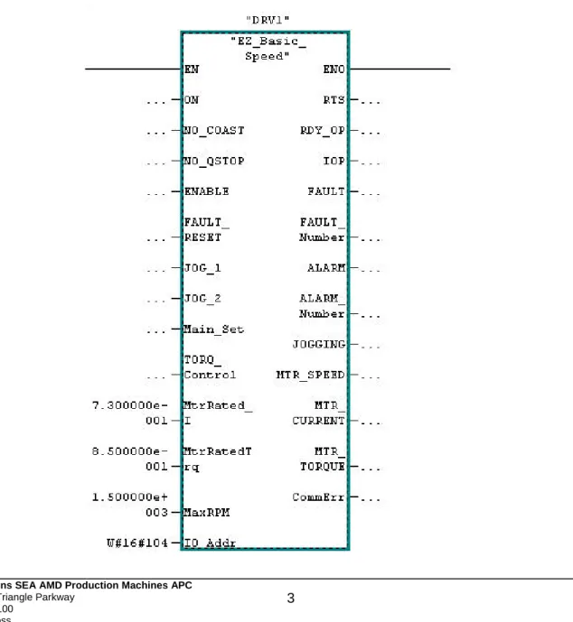
Block View of S120_Basic_Speed
From the block view you see the most commonly used Inputs and outputs to the drive. The left side of the block has the commonly used inputs such as; ON, NO_Coast, Enable, and JOG. The Right side contains commonly used Feedback from the drive such as RTS (Ready to Start), IOP (In Operation), and Motor_Speed. The left side contains normalization data needed as well as commonly used commands to the drive. This normalization data contains Motor current, Torque, and RPM. Typically for speed control the current and torque are nameplate data and the RPM is dependent on machine speed. The starting address peripheral address is on the bottom left side of the block. This is a hex value and can be found in decimal format in the hardware configuration of the S7 Hardware Configuration program. In this example the starting address for the drive was “260” so the address in the block is W#16#104.
Instance Data Block of S120_Basic_Speed Naming the Instance DB
Each instance DB used can be a specific name. This makes it easy to identify the axis as your are programming in S7. For example, the name of the block could be “DRV1” as in the example or it could be the Axis name – such as “Roughing Mill 1”. This way all of the DB bits and words specific to this drive are automatically named in an easy to understand format.
Common Drive Block Control Inputs
Table 4.0 (Block Inputs –Commonly used and Normalization)
Address Declaration Name Type Initial Value Comment
0.0 In ON BOOL False 1=OFF1
0.1 In NO_COAST BOOL False 1=OFF2
0.2 In NO_QStop BOOL False 1=OFF3
0.3 In ENABLE BOOL False 1=Enable
0.4 In FAULT_RESET BOOL False Fault Reset
0.5 In JOG_1 BOOL False Jog1 Speed
0.6 In JOG_2 BOOL False Jog2 Speed
2.0 In Main_Set INT. 0 Main n Set
4.0 In Torq_Control BOOL False 1= Torq Control
6.0 In MtrRated_1 REAL 100.0 For Amps Display
10.0 In MtrRatedTrq REAL 100.0 For Trq Display
14.0 In MaxRPM REAL 100.0 For n Act Display
18.0 In IO_Addr Word W#16#0 Hex Address
Common Drive Block Status Outputs
Note that CommErr is an integer value that can be used to diagnose communication problems with Profibus using SFC14 and SFC15. These SFCs are called by the Function Block. The most common error is that the input / output address on the block is not the same as the one in the Hardware Configuration in S7 Simatic Manager and subsequently the PLC.
Table 4.1 (Block Outputs –Commonly used, and Communication Error)
Address Declaration Name Type Initial Value Comment
20.0 Out RTS BOOL False Ready to Start
20.1 Out RDY_OP BOOL False Ready for
Operation
20.2 Out IOP BOOL False In Operation
20.3 Out FAULT BOOL False Fault Present
22.0 Out FAULT_Number INT. False Fault Number
24.0 Out ALARM BOOL False Alarm Present
26.0 Out ALARM_Number INT. False Alarm Number
28.0 Out JOGGING BOOL 0 Jogging Active
30.0 Out MTR_SPEED REAL False Speed in RPM
34.0 Out MTR_CURRENT REAL 100.0 Motor ABS Amps
38.0 Out MTR_TORQUE REAL 100.0 Motor Torque
Telegram to the Drive using the S120_Basic_Speed
This section shows the Bits and words sent to the Sinamics drive using the instance DB. This is the actual telegram to the drive. The commonly used bits in the previous section are internally mapped to the most used bits for convenience. Note that High and Low bytes are swapped when sending words to the drive. The order shown is as the telegram is received in the drive. Drive Folder refers to the section or folder in under the Drive Object in the Program Starter or Scout. Most control bits can be found in this folder, but some other folders are mentioned as they are the output of the control bits.
Word 1: Control Word 1
Control Word 1 is a basic drive Control word for enabling of operation and speed setpoint functions.
Address Drive Folder Name Type Initial Value Comment
57.0 Control Logic CW1.ON BOOL False OFF1 57.1 Control Logic CW1.NoOff2 BOOL False OFF2 57.2 Control Logic CW1.NoOff3 BOOL False OFF3 57.3 Control Logic CW1.Enable BOOL False Enable 57.4 Control Logic CW1.EnRFG BOOL True Enable RFG 57.5 Control Logic CW1.StRFG BOOL True Release RFG
57.6 Control Logic CW1.EnSpeedSet BOOL True Enable Speed Setpoint 57.7 Control Logic CW1.AknFault BOOL False Clear fault
56.0 CW1.Spare BOOL False Spare 56.1 CW1.Spare BOOL False Spare 56.2 Control Logic CW1.LB BOOL False PLC Control 56.3 Speed Setpoint CW1.Rev_Direction BOOL False Reverse n Set 56.4 Speed Setpoint CW1.JOG1 BOOL False Run - Jog 1 Speed 56.5 MOP Setpoint CW1.MOPRaise BOOL False Raise MOP 56.6 MOP Setpoint CW1.MOPLower BOOL False Lower MOP 56.7 Speed Setpoint CW1.JOG2 BOOL False Run - Jog 2 Speed
Word 2: Main Speed Setpoint
Word 2 is Main Speed Setpoint and is the primary speed setpoint to the drive.
Address Drive Folder Name Type Initial Value Comment
58.0 Speed Setpoint MainSpeedSet INT. 0 Main Speed Setpoint
Word 3: Control Word 2
Control word 2 is an additional Control Word for added features like Fixed Setpoints and Torque Control. Droop enable is only used in the drive objects that are Vector Control and have Droop Control activated.
Address Drive Folder Name Type Initial
Value
Comment
61.0 Fixed Setpoints CW2.FixedSetBit0 BOOL False Fixed Setpoint Bit 0 61.1 Fixed Setpoints CW2.FixedSetBit1 BOOL False Fixed Setpoint Bit 1 61.2 Fixed Setpoints CW2.FixedSetBit2 BOOL False Fixed Setpoint Bit 2 61.3 Fixed Setpoints CW2.FixedSetBit3 BOOL False Fixed Setpoint Bit 3 61.4 Speed Setpoint CW2.NoNegDir BOOL False Enable RFG 61.5 Speed Setpoint CW2.NoPosDir BOOL False Release RFG 61.6 CW2.Spare 6 BOOL False Spare 61.7 CW2.Spare 7 BOOL False Spare 60.0 CW2.Spare 8 BOOL False Spare 60.1 CW2.Spare 9 BOOL False Spare 60.2 CW2.Spare 10 BOOL False PLC Control 60.3 Setpoint Addition CW2.DroopEn BOOL False Enable Droop on VC
60.4 Torque Setpoints CW2.TorqControl BOOL False Switch to Torque Control 60.5 CW2.Spare 13 BOOL False Spare
60.6 CW2.Spare 14 BOOL False Spare 60.7 CW2.Spare 15 BOOL False Spare
Word 4: Additional Setpoint
The additional Speed Setpoint can be scaled in the drive and used as trim setpoint if needed.
Address Drive Folder Name Type Initial Value Comment
62.0 Speed Setpoint AddSetpoint INT. 0 Additional Speed Setpoint
Word 5: Torque Setpoint
The Torque Setpoint is switched via the Torque Control Bit is Control Word 2. See the Speed Setpoint Folder after the drive Script is written for more control information. Note that the Servo drive Torque Setpoint Folder is somewhat different but has similar function.
Address Drive Folder Name Type Initial Value Comment
64.0 Torque Setpoint TorqueSet INT. 0 Torque Setpoint from PLC
Word 6: Spare Word
This is a spare word and can be used in the drive as needed. A good example may be to use this word for Torque Limitation in the Torque Limiting Folder.
Address Drive Folder Name Type Initial Value Comment
66.0 SpareWord6 INT. 0 Spare Word
Telegram from the Drive using the S120_Basic_Speed
This section shows the Bits and words sent from the Sinamics drive to the instance DB. This is the actual telegram to the PLC. The commonly used bits in the Common Block Output section are internally mapped to the most used bits for convenience. Note that High and low bytes are swapped when sending words to or from the drive. The order shown is as the telegram is sent from the drive. Drive Folder refers to the section or folder in under the Drive Object in the Program Starter or Scout.
Word 1: Status Word 1
Status Word 1 is a basic drive Status word giving feedback on the status of enabling of operation and speed setpoint functions.
Address Drive Folder Name Type Initial Value Comment
45.0 Control Logic SW1.RdyToPwr BOOL False Drive Ready to Power 45.1 Control Logic SW1.RdyToOP BOOL False Drive Ready to Operate 45.2 Control Logic SW1.IOP BOOL False Drive In Operation 45.3 Control Logic SW1.Fault BOOL False Drive faulted
45.4 Control Logic SW1.NoOff2Act BOOL True 1= Coast to Stop Inactive 45.5 Control Logic SW1.NoOff3Act BOOL True 1= Quick Stop Inactive 45.6 Control Logic SW1.PowInhibit BOOL True Missing Enables 45.7 Control Logic SW1.Alarm BOOL False Drive has Alarm 44.0 Speed Messages SW1.nDeviationOK BOOL False Speed Deviation is OK 44.1 Control Logic SW1.LB_CR BOOL False Drive has PLC Life Bit 44.2 Speed Messages SW1.ReachedSpeed BOOL False Speed Value Reached 44.3 Control Logic SW1.T_I_LimOK BOOL False T or I Limit not Reached
44.4 Brake Control SW1.OpenBrake BOOL False Brake is Open 44.5 Control Logic SW1.MtrTempOK BOOL False Motor Temp. is Good 44.6 Speed Messages SW1.FWD_Dir BOOL False 1= Forward Direction 44.7 Control Logic SW1.DrvTempOK BOOL False Drive Temperature OK
Word 2: Actual Speed
Word 2 is Actual Speed of the drive’s motor. Use Reference Parameter Tab in Drive Configuration Folder to normalize this value – P2000.
Address Drive Folder Name Type Initial Value Comment
46.0 Profibus ActualSpeed INT. 0 Actual Speed
Word 3: Actual Motor Current
Word 3 is Actual Current of the drive’s Motor. Use Reference Parameter Tab in Drive Configuration Folder to normalize this value – P2002.
Address Drive Folder Name Type Initial Value Comment
48.0 Profibus ActualCurrent INT. 0 ABS Filtered Motor I
Word 4: Actual Motor Torque
Word 4 is Actual Torque of the drive’s Motor. Use Reference Parameter Tab in Drive Configuration Folder to normalize this value – P2003
Address Drive Folder Name Type Initial Value Comment
50.0 Profibus ActualTorque INT. 0 Filtered Motor Torque
Word 5: Drive Alarm Number
Word 5 shows any active Alarm number from the drive
Address Drive Folder Name Type Initial Value Comment
52.0 Profibus Alarm INT. 0 The Alarm Number
Word 6: Drive Alarm Number
Word 6 shows any active Fault number from the drive
Address Drive Folder Name Type Initial Value Comment