.
.
.
.
.
.
.
.
.
.
..
..
University of Virginia
Automobile Safety Laboratory
Out-of-Position Occupant
Testing (OOPS3 Series)
Cameron R. Bass
Jeff R. Crandall
Walter D. Pilkey
1.1: REFERENCES... 2
2: TEST DESCRIPTION... 3
2.1: TEST SETUP ... 3
2.1.1: MECHANICAL EQUIPMENT ... 3
2.1.2: PHOTOGRAPHY EQUIPMENT ... 4
2.1.3: DATA ACQUISITION SYSTEM ... 5
2.1.4: INSTRUMENTATION ... 5
2.2: TEST PROCEDURE ... 11
2.2.1: OCCUPANT PREPARATION... 11
2.2.2: DESCRIPTION OF TEST PROCEDURE ... 11
2.2.3: OCCUPANT POSITIONING ... 12 2.2.3.1: POSITIONING LOCATIONS ... 15 2.2.4: ENVIRONMENT ... 22 2.2.5: PHOTOGRAPHY... 22 2.2.6: DATA ACQUISITION... 23 2.2.7: DATA PROCESSING ... 23 3: TEST RESULTS ... 24 3.1: DESCRIPTION OF RESULTS ... 24 3.2: SENSOR DATA ... 24 3.3: THORACIC DATA... 41
3.3.1: CHEST DISPLACEMENT DATA ... 49
3.3.1.1: CRUX PERFORMANCE ... 51
3.3.1.2: CHESTBAND PERFORMANCE ... 55
3.3.2: DYNAMIC CHEST V*C DATA ... 56
3.4: PHOTOGRAPHIC RESULTS ... 57
3.5: SENSOR AND TEST FAILURES... 58
3.6: DISCUSSION OF RESULTS ... 59
3.6.1: SKIN/DISTANCE FROM MODULE STUDY ... 59
3.6.2: POSITIONING STUDY ... 61
3.6.3: COMPARISON WITH PREVIOUS ISO-2 TESTS AT ASL ... 64
and fatal injuries to out-of-position small female and child occupants. For example, surveys of crash data (NHTSA Special Crash Investigation Summary - 4/1/98) and laboratory tests conducted by NHTSA indicate that small female occupants are most likely to be injured by driver-side air bags owing to their stature and proximity to the steering wheel and air bag module. Recently, automobile manufacturers have begun ‘depowering’ driver- and passenger-side air bags as the result of concerns for these small female and child occupants.
The tests described in this report were designed to evaluate the relationship between air bag inflation aggressivity and occupant injury and response for a depowered driver-side air bag. Depowered driver-side air bags were deployed into the chest of a 5th Percentile Female Hybrid III dummy positioned against the cover of the air bag module in an effort to simulate worst-case chest loading. The occupant, air bags, and test conditions for the tests are summarized in Table 1.1. The tests assessed the ability of chestband contours, thoracic accelerations, and head accelerations to predict injury and to quantify air bag aggressivity in terms of measured occupant response parameters.
This report presents the results and analysis of nineteen air bag deployment tests with out-of-position occupants (OOPS) positioned according to the ISO-2 standard. The tests may be considered as two subseries. The first subseries is a study of the effect of skin conditions on the dummy response. These tests, OOPS3.1-OOPS3.6, comprise three different skin conditions repeated twice. These tests are skin on with breast forms on in OOPS3.1-OOPS3.2, skin on with breast forms off in OOPS3.3-OOPS3.4, and skin off in tests OOPS3.5-OOPS3.6.
The second subseries, OOPS3.7-OOPS3.19, is a lateral and vertical positioning study. Positions investigated include the dummy thorax centered on the air bag module, vertically displaced 2 cm and 4 cm upwards with respect to the steering wheel center, and laterally displaced 4 cm left with respect to the steering wheel module. A test matrix for the entire OOPS3 test series is shown in Table 1.1 below.
Goals of this research include evaluation of the position sensitivity of out-of-position deployment into a 5th Percentile Female Hybrid III dummy thorax as a part of a larger series in which occupant response and injury are being evaluated for a variety of occupant initial positions and air bag systems. Based upon data from these tests, a risk function that correlates observed cadaver injury with cadaver and dummy response is being developed using existing and future tests. The objective of this research is to develop a relationship between air bag inflation characteristics, occupant position, and cadaver injury. Using this relationship, guidelines will be established for air bag aggressivity thresholds and occupant position versus risk of injury.
The tests were conducted at the Automobile Safety Laboratory (ASL), operated by the Department of Mechanical, Aerospace, and Nuclear Engineering at the University of Virginia, Charlottesville, Virginia. Research is conducted under Cooperative Agreement No. DTNH22-93Y-07028 with the National Highway Traffic Safety Administration (NHTSA) of the U.S. Department of Transportation.
Skin 3.1 On with breasts Center Center ‘Nominal ISO-2’ Study 3.2 On with breasts Center Center ‘Nominal ISO-2’
3.3 On without breasts Center Center ‘Nominal ISO-2’
3.4 On without breasts Center Center ‘Nominal ISO-2’
3.5 Off Center Center ‘Nominal ISO-2’
3.6 Off Center Center ‘Nominal ISO-2’
Position 3.7 On with breasts Center Center ‘Chest on Module’, No chestbands Study 3.8 On with breasts Center Center ‘Chest on Module’
3.9 On with breasts Center Center ‘Chest on Module’
3.10 On with breasts Center Center ‘Chest on Module’
3.11 On with breasts Center 4 cm up ‘Chest on Module’
3.12 On with breasts Center 4 cm up ‘Chest on Module’
3.13 On with breasts 4 cm left Center ‘Chest on Module’, air bag tear 3.14 On with breasts 4 cm left Center ‘Chest on Module’, air bag tear
3.15 On with breasts 4 cm left Center ‘Chest on Module’
3.16 On with breasts 4 cm left Center ‘Chest on Module’
3.17 On with breasts Center 2 cm up ‘Chest on Module’
3.18 On with breasts Center 2 cm up ‘Chest on Module’
3.19 On with breasts Center 2 cm up ‘Chest on Module’
NOTES:
À Horizontal and Vertical Position refer to dummy sternum center positions relative to steering wheel center in the local axis system tangential to the steering wheel plane.
Á Comments are described in subsequent sections.
TABLE1.2: OOPS ISO-2 SERIES 3 TEST SUMMARY
TEST NUMBER OOPS3.1 – OOPS3.19 OCCUPANT
Type 5th % Female Hybrid III
Number VRTC 145
STEERING WHEEL AND AIR BAG
Type 1998 Ford
Model Taurus
1.1: REFERENCES
All Appendix references in this document are found in the ASL Descriptions and
Procedures Manual. To ensure conformity of data with other test facilities and between tests conducted at the ASL, standard conventions have been adopted for test procedures and data analysis procedures. The primary standards used are listed in Appendix A.1. Other references concerning equipment and procedures and relevant published literature are listed in Appendix B.
2.1.1: MECHANICAL EQUIPMENT
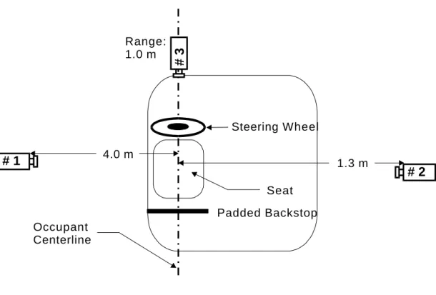
The static out-of-position tests were conducted in the Automobile Safety Laboratory’s OOPS test fixture shown in Figure 1. The fixture incorporates a rigid dummy seat with an adjustable pelvis locating pin in the occupant centerline. The steering wheel angle is 25 degrees (+/- 1 degree) from laboratory vertical. The steering wheel is attached to a five-axis steering column load cell mounted to a plate with horizontal and vertical adjustment positions. These positions allow variation of steering wheel position relative to the locating pin in increments of +/- 2 cm and +/- 4 cm from the vertical center position and +2 cm and +4 cm right of the horizontal center position. The center position of the steering wheel was selected to align the center of the sternum with the center of the air bag module in a coordinate system aligned with the dummy seat. Ganged hydraulic adjustment pistons were used to move the steering wheel into position in the local X-axis. Finally, a plywood backboard, cushioned with foam and padding, was positioned behind the bench to limit the rearward translation of the occupant following interaction with the air bag.
Table 2.1.1.1. A single bolt was used to attach the steering wheel to the center of the five-axis steering column load cell. Mating connectors, removed from steering column wiring harnesses, were used to connect the air bag modules to
the ASL squib-firing circuitry. The connectors were brought out the backs of the steering wheels to facilitate connection and to protect the mating connectors from squib and inflator heat.
2.1.2: PHOTOGRAPHY EQUIPMENT
The tests were all photographed with the same set of one high-speed motion picture film camera and two high-speed solid-state video cameras. The equipment used is described in Appendix D. Lights, on portable and fixed stands, were positioned as necessary to ensure adequate lighting of the tests. Cameras, views, and settings are summarized in Table 2.1.2.1 and the camera locations are shown schematically in Figure 2.
Synchronized photographic timing marks were recorded on the films in the film cameras, as described in Appendix D.1.4. Still photos were taken on Kodak Kodacolor 35mm ISO-200 color print film with a Nikon 6006AF single-lens reflex camera and with a Kodak DC-120 high-resolution digital still camera.
Part 1998 Ford Taurus Steering Wheel F7DC-3600-BAW
Air bag F8DB-54043B13-ABW*DP
TABLE 2.1.2.1: HIGH-SPEED MOTION PICTURE CAMERAS
Camera Lens
# Position View Type Frame Focal Aperture Range
À Á Rate  Length
1 Offboard, Driver’s Side Analysis R 2500 25.4 mm f: 4 4.0 m 2 Offboard, Passenger’s Side Overall K 1000 18.0 mm f: 2.8 1.3 m 3 Onboard, Angled Overhead Oblique K 1000 13.0 mm f: 2.8/4.0 1.0 m
NOTES:
À Camera positions are described in general in Appendix D.1.1. Also refer to Motion Picture Camera Position diagram, below.
Á Camera types:
R = Redlake Hycam
K = Kodak RO High-Speed Video
Seat Occupant Centerline Steering Wheel 4.0 m 1.3 m Padded Backstop # 2 # 1
Figure 2: Motion Picture Camera Position Diagram
2.1.3: DATA ACQUISITION SYSTEM
Electronic signals from sensors mounted on the test fixture and within the test subject were recorded and converted to digital data by the ASL’s 128-channel DSP Technology, model TRAQ-P, data acquisition system, which is described in detail in Appendix E.1. The data-collection process was controlled by DSP technology IMPAX 3.0 software, which is described in Appendix E.2. The post-test processing and conversion of the digital data to the NHTSA datatape format was done on IBM-compatible Pentium personal computers, using ASL software.
2.1.4: INSTRUMENTATION
The 5th Percentile Female Hybrid III was instrumented to acquire head, neck, and thoracic response during air bag deployment. The dummy instrumentation package included accelerometers at the conventional head and chest center-of-gravity locations. In addition, magnetohydrodynamic (MHD) angular rate sensors and accelerometers were attached to the posterior head and upper spine in locations analogous to those of cadaveric subjects tested in previous out-of-position tests. Data from the angular rate sensors allowed neck motion to be estimated from relative motion of the head and upper spine. Accelerometers on the second and fifth ribs recorded lateral acceleration of the rib cage. Upper and lower load cells recorded neck forces and moments. Chestbands were placed at the second and fifth ribs to determine local thoracic loading by the air bag systems. A sternal accelerometer and upper and lower sternum crux devices also recorded response of the anterior chest. In addition, contact forces between the occupant and the air bag were estimated from a five-axis load cell located at the upper end of the steering column. The sensors used are described in general, by type, in Appendix F.1 and
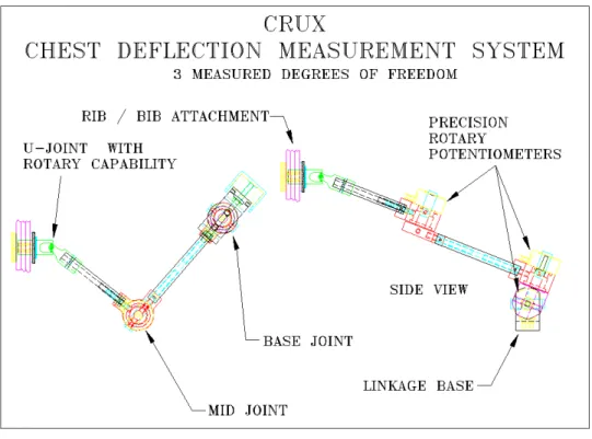
unit was originally conducted by GESAC, Inc., as a component of the NHTSA THOR advanced frontal dummy development program. The CRUX concept provides continuous 3D measurement of sternal displacement with respect to the dummy spine, and has been designed to function reliably at sternal velocities anticipated in OOP airbag environments. The CRUX design is comprised of a two-bar linkage, with three rotational degrees of freedom, which are continuously measured by three precision rotary potentiometers. Using software calculations, these angular measurements are converted to X, Y, and Z sternal displacements with respect to the CRUX base coordinate system (which is attached to the dummy spine). The CRUX design in schematic form is shown in Figure 3, and a CRUX mechanical assembly as currently installed as standard equipment in the 50th percentile male THOR dummy is presented in Figure 4. The two CRUX assemblies utilized in the 5th Percentile Female Hybrid III dummy tests conducted at the University of Virginia were custom modified versions of these THOR units, to adapt the CRUX devices into the limited available thoracic volume in the 5th Percentile Female Hybrid III. The CRUX units were located at the level of the first rib (upper CRUX unit) and the sixth rib (lower CRUX unit). To facilitate mounting, the upper CRUX unit was located 1.1 cm left of the sternum centerline and the lower CRUX unit was located 1.1 cm right of the sternum centerline.
Steering Load Steering X 5-Axis Denton 1765 Column Column, Y Load Cell
Upper Z
Moment Y
Z
5th % Female Head Head CG X Accelerometer Endevco 7264A Hybrid III Acceleration Y Accelerometer Endevco 7264A Z Accelerometer Endevco 7264A Head, Rear, X Accelerometer Endevco 7264A External  Y Accelerometer Endevco 7264A Z Accelerometer Endevco 7264A
Chest Chest CG X Accelerometer Endevco 7264A
Acceleration Y Accelerometer Endevco 7264A
Z Accelerometer Endevco 7264A Sternal Acceleration Sternum, Upper Y Accelerometer Endevco 7264A Sternum, Lower X Accelerometer Endevco 7264A Spinal Spine, Upper, X Accelerometer Endevco 7264A Acceleration External  Y Accelerometer Endevco 7264A Z Accelerometer Endevco 7264A
Neck Load Neck, Upper X 6-Axis Denton 1716
Y Load Cell Z
Neck, Lower X 5-Axis Denton 2150
Y Load Cell Z
Neck Moment Neck, Upper X 6-Axis Denton 1716
Y Load Cell Z
Neck, Lower X 5-Axis Denton 2150
Y Load Cell
Neck Rotation Head, Rear & X 2 Triaxial MHD ATA ARS-04 Spine, Upper, Y Angular Rate Sensors Dynacube External à Z Sensors
Sternum Deflection Sternum, Lower X 2 Triaxial GESAC Crux & Upper Y Deformation
Z Cruxes
Thorax Deflection 2nd Rib Ä Chestband Denton 36-gauge
transformed to the local anatomical reference frame. See Appendix I.6 for a description of the procedure used.
à Head and upper spine angular velocity data is used to compute neck rotation data, in the anatomical reference frame. See Appendix I.6 for a description of the procedure used.
Ä Each chestband is wrapped around the exterior of the thorax at the location of the specified rib and measures local curvature at 37 or 38 points around the circumference of the thorax. See Appendix F.2 for a more detailed description of the chestband and Appendix H.3 for a description of the chestband installation procedure.
Å Head Y- and Z-axis and head angular rate sensor X-axis accelerometer data are used to compute head center-of-gravity acceleration data. See Appendix I.6 for a description of the procedure used.
2.1.5: OCCUPANT
The 5th Percentile Female Hybrid III dummy is a standard device, supplied to the ASL by NHTSA. The dummy, S/N #145, was received on 7 July 1996. A complete description of the dummy may be obtained from the reference listed in Appendix B.2. Table 2.1.5.1 contains information about the clothing placed on the dummy during the tests. A grounded copper mesh shielding vest was used around the thorax, under the outer clothing layer, to shield the chestbands and internal instrumentation from possible electrical interference caused by static electrical discharges in the inflating air bag. A foam neck shield, supplied by First Technology Safety Systems, was installed around the Hybrid III neck to generally simulate a realistic neck diameter and to prevent entrapment of the air bag beneath the chin.
Special mounts were required for attaching the MHD angular rate sensors, used to measure neck flexion, to the Hybrid III dummy. The head rear mount consisted of a rectangular aluminum plate, approximately 9.5 mm thick, installed in place of the skull cover, and drilled and tapped to accept the MHD mounting screws. Spacers between the plate and the rear surface of the skull provided clearance for the internal head instrumentation cables. A removable cover protected the MHD sensor, but provided access for initial position measurements. The total mass of the mounting plate, cover assembly, mounting hardware, and sensor was adjusted to be approximately the same as that of the standard skull cover (including skin and mounting hardware). The upper spine MHD mount consisted of an aluminum bracket, which was attached to the top of the spine box by the four neck attachment bolts, and to which an aluminum plate, drilled and tapped for the MHD mounting screws, was attached. This plate was also used as the locating device for the rigid dummy positioning arm for the out-of-position fixture.
GENERAL INFORMATION
Type 5th Percentile Hybrid III
Number VRTC 145 Gender Female ANTHROPOMETRY Height (cm) 150.0 Weight (kg) 46.3 CLOTHING
Upper Body Inner Copper Mesh Shielding Upper Body Outer Cotton Shirt
All Hybrid III instrumentation was installed, and the installation verified, before the tests. The standard Hybrid III head and spine center-of-gravity mounting blocks (designed for Endevco model 7264 miniature accelerometers) were used to mount the Endevco 7264A accelerometers used for these tests. Holes were drilled and tapped in the inner aluminum sternum plate of the Hybrid III for attachment of the lower sternal accelerometer to the inner surface. After removal of the rear head cover, the MHD angular rate sensor mounting plate was attached to the rear of the skull. The four lower neck attachment bolts were removed, and the upper spine MHD mounting bracket was attached to the top of the spine box using longer bolts. Grounding wires were connected to the spine box and skull.
2.2.2: DESCRIPTION OF TEST PROCEDURE
With the chestbands laid flat, static reference data was recorded at the beginning of each test. The dummy, prepared as described above, was placed next to the test fixture in a seated position, with the arms raised above the head. Chestbands were installed and static chest contours were generated and verified with measurements, as described in Appendix H.3. The remaining external instrumentation was installed, and individual sensor locations and polarities were confirmed. The occupant was dressed, the shielding mesh vest was installed, and the occupant was moved into the test position. The steering wheel and air bag were installed with the steering wheel fixture retracted from test position, with attention given to the correct orientation of the wheel.
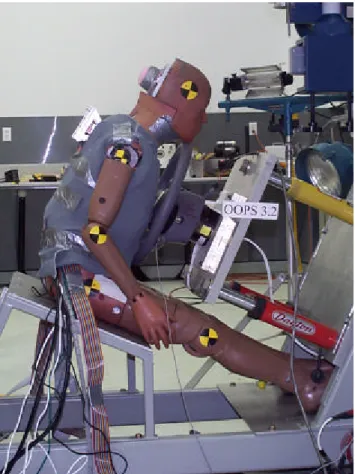
The occupant was then attached to a rigid dummy-positioning arm as shown in Figure 5. For several tests in the series, measurements of chest stiffness were taken using a 2.54 cm diameter cylinder mounted at the steering wheel center to the steering column load cell as discussed in Section 3.5.2. After the occupant was positioned relative to the steering wheel, as described in Section 2.2.3, the steering wheel and air bag module were moved into test position. Following this, the rigid positioning arm was carefully removed so as not to disturb the dummy position. Final positioning measurements were taken as described below. In addition, the initial orientations of the MHD angular rate sensors were measured and noted, using the procedure described in Appendix H.2. Crosshair-type photographic targets were attached to the occupant at anatomical landmarks and their coordinates, relative to the reference target on the test fixture, were measured and noted using a Faro Arm positioning device. Measurements of head angles were also taken. (Refer to Table 2.2.3.2.) In addition, digital photographs of the final occupant positioning were taken.
After the air bag deployment, digital photographs were taken of the resting position of the occupant. The occupant was removed from the test fixture and the chestbands were removed and laid flat. The digital and high-speed video data were saved to computer disk. The various types of data were processed, as described in Section 2.2.7. The procedures used throughout the tests for motion picture photography and data acquisition are described in Sections 2.2.5 and 2.2.6.
The positioning guidelines for the ISO-2 tests came from the ISO DTR 10982 draft standard on “Road Vehicles - Test Procedures for Evaluating Out-of-Position Vehicle Occupant Interactions with Deploying Air Bags” (referenced in Appendix B.11). The 5th Percentile Female Hybrid III occupant used in this test series was positioned according to this procedure, briefly reviewed here. A general diagram of this position is presented in Figure 9.
There is some ambiguity in the interpretation of ISO-2 positioning. The presumed intention of the ISO-2 position is to investigate maximum thoracic loading of an out-of-position occupant. To achieve this position, the chin is placed just on top of the upper rim of the steering wheel, without hanging the head over the rim, and the chest is placed in direct contact with the air bag module with the spine parallel to the plane of the steering wheel. However, the breast forms of the 5th Percentile Female Hybrid III dummy allow several different interpretations of
For OOPS3.1 – 3.6: The position was ISO-2 with chin on wheel but not hanging over the wheel. The chest is in close proximity to the air bag with the dummy spine parallel to the plane of the steering wheel. In subsequent text, this is termed “Nominal ISO-2” as shown in Figure 6.
Using the 5th Percentile Female Hybrid III Dummy, this test condition places the dummy skin with breasts on the air bag module, but not deformed by the air bag module. Tests OOPS3.1-3.6 were a study of occupant response using different dummy skin conditions and the “Nominal ISO-2” position with the chin and spine positions the same for all tests. This implied that the thorax contact point moved away from the air bag, over 5 cm from the tests using the dummy skin with breasts to the dummy with no skin as is discussed in Section 3.8.1.
2. Chest on Module:
For OOPS3.7 - 3.19: The ISO-2 position was relaxed for tests OOPS3.7-3.16 to put the chest in direct contact with the air bag module with some nominal force that allowed static equilibrium to be maintained between the dummy chest and the air bag module. In subsequent text, this is termed “Chest On Module” as shown in Figure 7.
The Chest On Module positioning implies that the dummy breasts will be deformed by the air bag module. To ensure this, the dummy was positioned with the thorax pressing 100 N force on the air bag module as measured using the steering column load cell. In this position, the spine angle was maintained parallel to the plane of the steering wheel. Occupant positioning was accomplished using an adjustable pin located between the thighs of the dummy, resting against the occupant pelvis. The chin was placed on the top of the steering wheel. For the Nominal ISO-2 position, the chin was placed in the middle of the steering wheel, not hanging over. For the Chest On Module position, the chin was allowed to hang over the steering wheel if necessary; for this position, a small wedge of foam padding was used to prevent the occupant chin from catching on the steering wheel under air bag deployment. For both positions, the spine angle was 25 degrees (+/- 1 degrees) from vertical (i.e. parallel to the steering wheel).
range from photo target locations on the head and occupant H-point to bolts on the dummy to fixed locations on the test device. Position measurements taken at these locations are shown in Table 2.2.3.2 below.
TABLE 2.2.3.1:
FARO ARM MEASUREMENT LOCATIONS
POINT # DESCRIPTION
1 Right Head Photo Target 2 Left Head Photo Target 3 Upper Right Spine Bracket Bolt 4 Upper Left Spine Bracket Bolt 5 Lower Right Spine Bracket Bolt 6 Left Shoulder Bolt
7 Right Shoulder Bolt 8 Left H-Point Photo Target 9 Right H-Point Photo Target 10 Wheel Fixture Reference
the shoulder bolts depend on details of orientation of upper arm, the three fixed bolt positions represent most accurate determination of positioning tolerance for the runs. For runs OOPS3.1 – OOPS3.6, the positioning accuracy based on bolt locations was within 0.37 cm in local X, +/-0.29 cm in local Y, and +/-0.2 cm in local Z. For runs OOPS3.7 – OOPS3.19, the positioning accuracy based on bolt locations was +/-0.36 cm in local X, +/-0.5 cm in local Y, and +/-0.32 cm in local Z.
An indication of the intrinsic accuracy of the Faro Arm measurement is the positioning accuracy derived from measurements made to a fixed reference location. For this location, positioning accuracy was +/- 0.06 cm in local X, +/- 0.23 cm in local Y, and +/- 1.3 cm in local Z.
OOPS3.6 OOPS3.5 OOPS3.4 OOPS3.3 OOPS3.2 OOPS3.1 Head Right X 222.7 225.5 222.6 224.9 223.6 222.5 Y -62.8 -67.1 -68.8 -71 -73 -71.5 Z 684.6 686.2 683.5 682.9 684.9 684.5 Head Left X 209.1 210.5 206.6 205.4 207.8 205.3 Y 74.5 70.7 69 66.3 62.5 66.5 Z 661.8 668.3 667.4 669.9 670.6 668.4
Bolt Upper Right X -2.4 -3.7 -7 -6 -6.8 -9.6
Y -34.3 -34.9 -33.7 -33.9 -37.8 -38.9
Z 522 524.9 522.4 523.1 525.4 525.1
Bolt Upper Left X -3.3 -4.5 -7.3 -6.8 -7.3 -10.7
Y 38.9 38.4 39.5 39.5 35.6 35.2
Z 521.4 524.8 522.2 522.9 525.4 525.4
Bolt Lower Right X -15.4 -16.9 -19.3 -18.6 -19.1 -21.4
Y -35.2 -35 -33.3 -33.7 -37.8 -39.1 Z 447.3 449.8 447.1 447.8 450.2 450.5 Shoulder Left X 106.3 105.9 104.7 105.7 104.2 100.4 Y 154.4 154.8 154.4 154.9 150.5 149.9 Z 432.1 438.2 435.1 435.5 439.4 436.8 Shoulder Right X 139.5 138.6 135.8 136.2 136.1 135.1 Y -151.2 -150.6 -150.1 -149.5 -155.5 -154.6 Z 427.6 431.8 427.6 427.7 431.4 430.1 H-Point Left X 199.3 195.3 200.1 198.9 187.2 172.4 Y 154.2 154.9 154.6 154.8 339.3 339.7 Z 85.2 82.8 83.7 85.1 82.7 80.5 H-Point Right X 184.9 178.2 182.3 175.8 NA 184.5 Y -146.4 -146.4 -143 -146.4 NA -342 Z 81 78.7 79.2 77.7 NA 83.5 Steering Wheel Ref. X 478.8 479.4 479.1 479.9 479.8 479.4 Y -1.4 -1.8 -0.4 -0.7 -0.2 -1.7 Z 593.6 594 593.2 593.8 593.5 594.1
OOPS3.12 OOPS3.11 OOPS3.10 OOPS3.9 OOPS3.8 OOPS3.7 Head Right X 260.2 266.5 205.6 210.9 206 209.7 Y -69.5 -64.6 -69.4 -67.5 -69.1 -66.8 Z 662.3 663.4 690.2 691.2 690.4 693.6 Head Left X 264.7 244.5 199.8 200.7 199.3 202.5 Y -70.2 72.2 67.8 68.4 68.2 68.7 Z 657.9 650.6 669.1 670.8 669.2 671
Bolt Upper Right X -7.5 -3.8 -9.3 -4.6 -6.7 -4.8
Y -39.2 -35.1 -35 -37.4 -36.8 -37.8
Z 520.2 524.9 522.2 524.9 523.8 526.5
Bolt Upper Left X -8.4 -4 -9.2 -5.4 -7.6 -5.7
Y 34.4 38 38.3 35.8 36.4 35.5
Z 520.6 524.8 522.2 524.9 523.9 526.2
Bolt Lower Right X -20.7 -16.9 -21.7 -17.6 -19.4 -17.6
Y -39.1 -35.7 -34.8 -37.3 -36.9 -38.3 Z 444.7 449.8 446.9 449.7 448.9 451.2 Shoulder Left X 101.6 104.9 102.9 105.6 103.4 104.8 Y 150.2 153.9 154.4 151.5 152.9 151.7 Z 432.3 436.7 437.3 437.3 435 437.9 Shoulder Right X 136.3 140.2 NA 138.5 137.1 138.9 Y -152.5 -151.8 NA -153.8 -153.5 -152.6 Z 425.9 431.9 NA 428.2 431.7 430.8 H-Point Left X 187.4 187.2 187.5 187.1 189.1 188.6 Y 155 154.8 154.3 154.7 153.9 152.8 Z 82 83 82.6 82.5 79.4 81.2 H-Point Right X 187.3 186.1 187.8 186.4 189 187.8 Y -150.2 -149.5 -150.1 -151 -151 -152.4 Z 76.3 76.3 77.4 76.4 77.8 78.6 Steering Wheel Ref. X 462.4 462.4 462.7 462.5 462.2 461.6 Y -1.5 -1.1 -1.3 -0.5 -0.8 -2.1 Z 594.3 594.4 594.2 593.9 594 594.2
OOPS3.18 OOPS3.17 OOPS3.16 OOPS3.15 OOPS3.14 OOPS3.13 Head Right X 231.3 229 230.1 230.7 227.6 228 Y -63.6 -68.7 -63.5 -68.7 -59.5 -68 Z 687.2 686.5 686.5 685.7 684.6 684 Head Left X 215.2 213.8 215.3 214.8 212.2 210.6 Y 72.8 67.3 72 67.7 76.7 68.5 Z 662.6 666.4 662 663.7 661.7 665.1
Bolt Upper Right X -2.2 -2.4 -4.4 -3.6 -7.4 -5.5
Y -37.7 -38.3 -38.2 -39.1 -29.8 -37.2
Z 524.7 525.8 523.6 524.7 524 524.1
Bolt Upper Left X -3.2 -3.3 -5 -4.1 -7 -6
Y 35.6 35.1 35.6 34.4 43.4 35.9
Z 524.3 525 524.1 525.4 522.8 524.1
Bolt Lower Right X -15 -14.8 -16.7 -16.6 -19.5 -18.6
Y -38.2 -38.8 -38.2 -39.6 -30.6 -36.7 Z 449.4 450 449 449.1 448.5 449.2 Shoulder Left X 106.7 107.1 105.3 105.8 104.3 105 Y 151.5 150.5 150.7 150.1 156.4 150.1 Z 435.6 436.2 434.9 437 433.5 430.9 Shoulder Right X 141.3 141.5 140.9 141.4 136.1 137.1 Y -153.5 -153.2 -152.2 -153.3 -146.9 -152.9 Z 429 430.6 429.8 429.1 430.6 433.4 H-Point Left X 187.8 187.2 186.2 186.7 187 186.1 Y 151.9 150.4 152.1 150.9 154.4 154.4 Z 81.8 81.7 81.1 80.5 81.1 83.3 H-Point Right X 189.1 188.3 189.2 185 187 187.1 Y -153.3 -154.5 -153.2 -155.3 -149.9 -149.8 Z 75.7 74.7 74.5 74.9 80.3 77 Steering Wheel Ref. X 462.5 462.6 462.3 462.3 462.6 462.6 Y -5.4 -5.4 -5.2 -4.8 -1.2 -1.7 Z 592.9 593 592.3 591.9 594.4 594.3
Location Axis Test Number OOPS3.19 Head Right X 230.7 Y -72.2 Z 682.6 Head Left X 213.1 Y 64.6 Z 667.5
Bolt Upper Right X -2.3
Y -39.7
Z 525.4
Bolt Upper Left X -3.7
Y 33.3
Z 524.7
Bolt Lower Right X -15.9
Y -40.1 Z 449.9 Shoulder Left X 105.4 Y 149.6 Z 435.2 Shoulder Right X 142 Y -153.8 Z 427.1 H-Point Left X 186.8 Y 150.3 Z 81.4 H-Point Right X 189.4 Y -154 Z 75.2 Steering Wheel Ref. X 461.7 Y -5.2 Z 592.8 NOTES:
Á Coordinates are X-, Y- and Z-Axis distances from the test fixture reference locations in the local reference frame with the Z-Axis aligned with the vertical plane of the steering wheel. The local X-Axis is normal to the plane of the steering wheel directed from the face of the module into the steering wheel.
controlled room. The dummy was placed in the room 10 hours before the tests to allow the mechanical structures to equilibrate with the ambient temperature. Less than 3 0C temperature variation was seen over this time. Environmental data at airbag initiation for the OOPS3.1 – OOPS3.19 tests is presented in Table 2.2.4.1. The average test-time temperature for all tests was 28.3 0C (+/- 1.1 0C standard deviation) with an average relative humidity of 65.5 % (+/- 3.5 % standard deviation).
TABLE 2.2.4.1: TEST ENVIRONMENTAL DATA
TEST 3.1 3.2 3.3 3.4 3.5 3.6 3.7 3.8 3.9 3.10 3.11 3.12 3.13 3.14 3.15 3.16 3.17 3.18 3.19 Date Oct 23 Oct 23 Oct 24 Oct 24 Oct 24 Oct 24 Nov 7 Nov 7 Nov 10 Nov 10 Nov 11 Nov 11 Nov 11 Nov 11 Nov 18 Nov 18 Nov 20 Nov 20 Nov 20 Temperature (0 C) 28.3 29.3 27.0 28.9 30.2 29.4 28.9 28.6 28.4 27.8 27.0 28.3 28.9 28.0 28.3 29.1 28.1 28.8 25.1 Relative Humidity (%) 64 64 62 64 66 68 71 71 68 68 69 69 68 67 60 61 62 61 62 2.2.5: PHOTOGRAPHY
During the pre-impact phase of each test, the motion picture film cameras were test-run without film. The high-speed video cameras, photographic lighting system, and timing mark generator were activated in a simulation of the actual impact event, to test the various systems and the interconnections between them. After these tests, the film cameras were loaded with film.
When the occupant was positioned for the air bag impact, adhesive-backed crosshair-type photo targets were placed at important points on the occupant, to facilitate post-test motion picture analysis tracking of the various body segments. The global X-, Y-, and Z-axis coordinates of the occupant measurement points relative to the local reference frame of the test fixture were measured and recorded. The measured coordinates are listed in Section 2.2.3.2. The run number was posted on paper signs, visible in all camera views. Still photos of the final occupant position were taken before the air bag deployment was initiated and similar photos were taken immediately after the event. The pre- and post-deployment photos appear in Sections 2.2.4.1 and 3.1.3.2 respectively.
The impact event was initiated by manually activating the camera controller, which started the film cameras running. After a pre-programmed delay of approximately one second, the data acquisition system trigger circuitry was automatically activated, resulting in the simultaneous triggering of the high-speed video camera, timing mark generator, data acquisition system, and air bag deployment circuitry.
After the test series, the films were commercially developed and printed. The motion picture film images were edited to remove insignificant pre- and post-impact frames and the
2.2.6: DATA ACQUISITION
Standard data acquisition procedures, as described in Appendix H.6, were used in the collection of pre-impact and impact data. Sensors used for these tests were verified to be working properly before the tests and were monitored during the pre-impact preparations, using the procedures described in Appendix F.3. All Hybrid III instrumentation was installed, and the installation verified, before each test. Correct installation and operation of the chestbands was confirmed after they had been installed on the occupant, using the procedure described in Appendix H.3.
During the pre-impact phase of each test, the trigger circuitry, photographic timing mark generator, air bag squib-firing circuitry, camera controller, and high-speed video systems were activated in a simulation of the actual impact event, to test the various systems and the interconnections between them.
The various system settings used for the impact data collection are
summarized in Table 2.2.6.1. The
system was triggered manually through the camera controller, which introduced a delay of approximately one second to allow the motion picture camera to reach operating speed. After the delay, the trigger circuitry was automatically activated and simultaneously triggered the data acquisition system, photographic timing mark generator, and high-speed video system, and initiated deployment of the air bag.
2.2.7: DATA PROCESSING
Standard procedures, described in Appendix I, were used for all post-test data processing.
Appendix I.1 covers the processing done to all the data. Resultant accelerations were calculated from their orthogonal components, as described in Appendix 1.3. Neck flexion angles were computed using data from the head rear and upper spinal MHD angular rate sensors. The processes used are described in Appendix I.7. Finally, standard NHTSA datatape files were created, as described in Appendix I.2, and a set of IBM-compatible diskettes, which constitute the datatape, were prepared for delivery to NHTSA.
TABLE 2.2.6.1:
DATA ACQUISITION PARAMETERS
Number of Channels Used 118
Sampling Rate 10,000 samples/ second Pre-Trigger Samples 1,280 / channel Post-Trigger Samples 8,960 / channel Total Samples 10,240 / channel À
Pre-Trigger Duration 128 ms. Post-Trigger Duration 896 ms.
Total Duration 1,024 ms.
Anti-Aliasing Filter Cutoff Frequency 3300 Hz.À NOTE:
ÀSee Appendix I.1 for a discussion of record length and the frequency content of the data, as presented on the datatape.
In addition to the datatape, motion pictures, and high-speed video, data from the tests is presented in several different forms in this section. Minima and maxima and the times at which they occurred from sensor channels is presented and discussed in Section 3.2. In Section 3.3, thoracic data measured and calculated from various sensors is discussed. This discussion includes an examination of thoracic injury criteria including sternal displacements and sternal viscous response. Photographic results are presented in Section 3.4 and include a summary of the occupant response and kinematics from high-speed video and film. Sensor and test failures are discussed in Section 3.5, and a discussion of test results is presented in Section 3.6. This discussion includes the effect of dummy skin and distance from the module on occupant response, and the effect of position on dummy and occupant response.
3.2: SENSOR DATA
A summary of maximum and minimum values of accelerometer and load cell sensor data is presented in Table 3.2.3. The steering axial column load (Steering Column Load X-axis) measured in the tests shows a large variation among tests that correlates with occupant response, generally lower in value with lower occupant response and higher in value with higher occupant response. Steering column moment values represent vertical and lateral oscillations in the air bag as it interacts with the occupant.
Head center-of-gravity acceleration values seen in Table 3.2.3 are well below injury tolerance values as expected for these predominantly thoracic out-of-position tests. Peak resultant values for all tests are significantly below 60 g’s, the standard injury tolerance value for a 50th Percentile Male Hybrid III dummy. Head injury criterion (HIC) calculated for each test is presented in Table 3.2.1. HIC values for all tests peak within 20 ms of air bag deployment, and are all substantially lower than the 50th Percentile Male Hybrid III dummy head injury tolerance value of 1000.
TABLE 3.2.1: HEAD INJURY CRITERION (HIC)
TEST 3.1 3.2 3.3 3.4 3.5 3.6 3.7 3.8 3.9 3.10 3.11 3.12 3.13 3.14 3.15 3.16 3.17 3.18 3.19
Peak HIC 11 11 10 9 14 17 27 34 25 25 23 24 18 8 22 21 32 25 50
@ Time (ms) 10.7 10.2 10.3 10.5 19.9 15.0 10.3 10.8 10.5 10.8 11.5 11.5 10.0 9.5 17.8 10.3 10.3 10.1 12.3 Accelerometers mounted externally on an MHD angular rate sensor attached to the back of the dummy head show similar peak acceleration values as the head center-of-gravity accelerometers. In no case does the local acceleration value go above 60 g’s.
The chest center-of-gravity acceleration resultant for the test series is shown in Table 3.2.2. The peak chest CG resultant acceleration values are above the 60 g level for the tests OOPS3.8 – OOPS3.10 with the dummy sternum centered on the air bag module in the Chest on Module position. In addition, this average peak CG acceleration is 44% larger for the Chest on
TABLE 3.2.2: CHEST CG RESULTANT ACCELERATION PEAK TEST 3.1 3.2 3.3 3.4 3.5 3.6 3.7 3.8 3.9 3.10 3.11 3.12 3.13 3.14 3.15 3.16 3.17 3.18 3.19 Peak Accel. (g’s) 32 33.6 28.1 28.5 22.6 22.7 51.4 60.8 60.5 61.8 40.1 38.9 25.1 19 31.8 30.7 50.7 56.2 50.7 @ Time (ms) 13.1 13.5 13.6 13.8 11 11.3 13.3 13.3 13.4 13.8 12.8 12.9 13.2 12.5 12.3 12.6 12.7 12.3 13.5 Owing to electrical noise, a substantial number of neck load and neck moment sensors shown in Table 3.2.3 have questionable data during the test. However, two tests, the sternum-centered case of OOPS3.9 and the sternum up 4 cm case of OOPS3.11, are expected to be the limiting cases for neck injury. These tests have good data on all neck load cell channels. Both Chest on Module tests show upper and lower neck axial tension loads of less than 1600 N. Also, neck shear values for both tests are well below 2000 N. Similarly, neck moments in flexion for both the upper and lower neck are relatively small. Relatively large neck moment values in extension for these tests occur after occupant/air bag interaction upon rebound. These values, however, are obtained outside the region of primary air bag/occupant interaction investigated in this study.
Magnetohydrodynamic (MHD) angular rate sensors were used to determine neck flexion for all tests. Similar time histories of neck flexion were seen for the occupant-centered tests in
OOPS3.1-OOPS3.7 and OOPS3.9 shown in Figure 10. Data spikes in MHD channels in
OOPS3.8, OOPS3.10-OOPS3.12, and OOPS3.17-OOPS3.19 prevented comparison of processed MHD data from those tests. In contrast, spine flexion is lower for tests in which the dummy is offset 4 cm to the left of the air bag center. Figure 11 shows a comparison of the dummy-centered tests of OOPS3.1 and OOPS3.2 with the dummy-offset-left tests of OOPS3.15 and OOPS3.16. In the dummy-offset tests, the spine flexion is initially steeper. Owing to lower total occupant forcing, however, the time evolution of the flexion is ultimately shallower than with the occupant centered on the air bag.
0 2 4 6 8 10 0 10 20 30 40 50
Elapsed Time from Air Bag Deployment (ms)
Neck Flexion (deg)
Oops3.4 Oops3.5 Oops3.6 Oops3.7 Oops3.9
Figure 10: Neck Y Flexion from MHD Data - Dummy Sternum Centered on Air Bag Module
0 2 4 6 8 10 12 14 16 0 10 20 30 40 50
Elapsed Time from Air Bag Deployment (ms)
Neck Flexion (deg)
Oops3.1 - Vertically Centered Oops3.2 - Vertically Centered Oops3.15 - 4 cm Offset Left Oops3.16 - 4 cm Offset Left
Steering Column
Steering Steering N 600 X OOPS3.1 -136.17 6.50 6716.40 9.20
Column Column, N 600 OOPS3.2 -440.05 6.30 7485.60 9.90
Load Upper N 600 OOPS3.3 -476.02 6.20 6572.60 8.30
N 600 OOPS3.4 -357.91 6.30 6119.20 9.70 N 600 OOPS3.5 -607.94 7.40 4730.90 8.80 N 600 OOPS3.6 -73.31 94.60 4361.10 30.30 N 600 OOPS3.7 -147.9Ä 90.3 8348.6Ä 10.9 N 600 OOPS3.8 -96.9 75.2 9815.7 10.0 N 600 OOPS3.9 -140.3 96.4 6678.5 9.6 N 600 OOPS3.10 -47.4 98.5 8098.3 10.5 N 600 OOPS3.11 -412.8 99.3 5664.3 11.3 N 600 OOPS3.12 -310.2 99.4 6494.8 10.5 N 600 OOPS3.13 -156.7Ä 74.3 7175.1Ä 9.4 N 600 OOPS3.14 -79.0Ä 98.1 6726.9Ä 8.4 N 600 OOPS3.15 -293.0 99.2 6449.2 10.1 N 600 OOPS3.16 -198.1 99.3 6127.9 9.9 N 600 OOPS3.17 -175.8 94.5 9146.8 10.1 N 600 OOPS3.18 -167.0 98.2 9063.6 9.7 N 600 OOPS3.19 -204.1 65.6 5873.2 11.8 N 600 Y OOPS3.1 -359.67 13.50 302.31 12.60 N 600 OOPS3.2 -554.91 9.20 459.58 15.30 N 600 OOPS3.3 -525.01 22.90 306.67 17.10 N 600 OOPS3.4 -521.38 28.90 230.46 36.10 N 600 OOPS3.5 -527.67 21.30 468.54 27.20 N 600 OOPS3.6 -362.36 28.20 303.33 25.10 N 600 OOPS3.7 -490.6 10.6 388.3 15.1 N 600 OOPS3.8 -2386.1Ä 9.7 737.6Ä 18.4 N 600 OOPS3.9 -527.5 23.2 766.9 14.9 N 600 OOPS3.10 -2189.9Ä 13.4 540.5Ä 23.2 N 600 OOPS3.11 -614.9 12.2 540.8 24.7 N 600 OOPS3.12 -513.1Ä 22.0 507.5Ä 10.9 N 600 OOPS3.13 -2496.9Ä 9.4 620.9Ä 11.6 N 600 OOPS3.14 -2338.6Ä 9.0 361.0Ä 13.6 N 600 OOPS3.15 -1109.6 31.8 660.7 11.6 N 600 OOPS3.16 -1463.0 35.1 409.5 12.1 N 600 OOPS3.17 -1848.3Ä 10.1 483.8Ä 30.0 N 600 OOPS3.18 -3105.5Ä 9.6 470.9Ä 16.7 N 600 OOPS3.19 -435.3 27.0 609.3 17.8 N 600 Z OOPS3.1 -992.92 10.10 1354.80 8.70 N 600 OOPS3.2 -1437.00 10.10 1599.40 8.80 N 600 OOPS3.3 -1517.50 9.90 1528.80 8.40 N 600 OOPS3.4 -1403.40 9.80 1538.70 8.40
N 600 OOPS3.5 -786.38 10.60 1213.40 8.80 N 600 OOPS3.6 -1152.90 10.70 991.06 34.50 N 600 OOPS3.7 -1935.1 10.7 1407.1 9.0 N 600 OOPS3.8 -3638.6Ä 10.6 1356.4Ä 8.6 N 600 OOPS3.9 -963.2 26.4 935.1 8.5 N 600 OOPS3.10 -2984.8Ä 11.0 1242.1Ä 37.2 N 600 OOPS3.11 -736.2 14.1 1436.3 8.9 N 600 OOPS3.12 -1037.2Ä 6.5 1657.7Ä 8.8 N 600 OOPS3.13 -3173.1Ä 8.4 1122.9Ä 20.0 N 600 OOPS3.14 -2576.7Ä 7.9 973.5Ä 5.0 N 600 OOPS3.15 -1047.0 10.4 1379.3 8.4 N 600 OOPS3.16 -1486.8 9.9 1137.3 8.4 N 600 OOPS3.17 -1812.8Ä 10.2 978.0Ä 8.4 N 600 OOPS3.18 -2893.3Ä 9.7 1177.3Ä 8.6 N 600 OOPS3.19 -1073.1 14.4 884.6 9.2 Steering Nm 600 Y OOPS3.1 -206.28 26.80 32.98 5.20 Column Nm 600 OOPS3.2 -243.28 25.50 41.47 62.10 Moment Nm 600 OOPS3.3 -269.79 27.10 36.83 34.10 Nm 600 OOPS3.4 -219.93 13.60 60.83 20.10 Nm 600 OOPS3.5 -126.04 25.30 79.84 32.30 Nm 600 OOPS3.6 -132.32 10.20 144.88 32.60 Nm 600 OOPS3.7 -346.3 27.7 55.2 21.7 Nm 600 OOPS3.8 -430.3Ä 25.7 31.7Ä 5.5 Nm 600 OOPS3.9 -309.3 26.5 39.5 88.1 Nm 600 OOPS3.10 -367.3Ä 11.4 26.2Ä 5.5 Nm 600 OOPS3.11 -303.9 14.1 103.4 99.7 Nm 600 OOPS3.12 -310.6Ä 14.9 83.9Ä 99.7 Nm 600 OOPS3.13 -369.6Ä 9.4 91.8Ä 48.4 Nm 600 OOPS3.14 -321.7Ä 9.0 113.0Ä 43.3 Nm 600 OOPS3.15 -194.3 28.3 78.3 38.5 Nm 600 OOPS3.16 -244.9 9.8 71.0 42.7 Nm 600 OOPS3.17 -444.4Ä 14.1 26.4Ä 5.1 Nm 600 OOPS3.18 -488.1Ä 9.6 29.3Ä 4.5 Nm 600 OOPS3.19 -264.1 14.4 71.0 22.5 Nm 600 Z OOPS3.1 -53.15 30.00 33.57 13.40 Nm 600 OOPS3.2 -62.10 32.30 52.57 42.50 Nm 600 OOPS3.3 -42.26 24.50 48.02 20.90 Nm 600 OOPS3.4 -46.98 35.90 114.09 28.10 Nm 600 OOPS3.5 -129.19 27.20 82.56 36.00 Nm 600 OOPS3.6 -57.81 35.60 52.38 41.80 Nm 600 OOPS3.7 -41.4 16.1 66.0 34.7 Nm 600 OOPS3.8 -97.5Ä 17.2 36.3Ä 42.7 Nm 600 OOPS3.9 -177.5 30.5 24.3 22.9 Nm 600 OOPS3.10 -67.9Ä 10.9 38.1Ä 29.2
Nm 600 OOPS3.11 -193.4 22.1 18.6 5.9 Nm 600 OOPS3.12 -39.9Ä 10.9 70.4Ä 22.0 Nm 600 OOPS3.13 -82.6Ä 8.4 284.5Ä 17.5 Nm 600 OOPS3.14 -99.1Ä 7.8 360.1Ä 23.7 Nm 600 OOPS3.15 -19.2 8.0 287.6 31.8 Nm 600 OOPS3.16 -18.7 8.0 363.9 35.5 Nm 600 OOPS3.17 -142.2Ä 17.9 23.4Ä 25.9 Nm 600 OOPS3.18 -82.2Ä 9.4 48.8Ä 24.6 Nm 600 OOPS3.19 -85.1 19.1 94.6 26.9 Head
Head Head, Center g's 180 X OOPS3.1 -14.60 20.50 0.50 8.50
Acceleration of Gravity g's 180 OOPS3.2 -17.39 21.00 0.55 8.60
g's 180 OOPS3.3 -16.41 17.80 0.58 8.60 g's 180 OOPS3.4 -13.27 17.50 0.80 8.70 g's 180 OOPS3.5 -15.07 22.30 0.65 8.40 g's 180 OOPS3.6 -13.08 22.70 0.84 8.30 g's 180 OOPS3.7 -25.2 31.8 0.1 6.9 g's 180 OOPS3.8 -27.7 27.9 0.3 8.3 g's 180 OOPS3.9 -22.8 30.5 0.1 7.7 g's 180 OOPS3.10 -21.5 21.9 0.2 8.1 g's 180 OOPS3.11 -21.9 30.2 0.3 7.4 g's 180 OOPS3.12 -18.8 33.8 0.2 7.3 g's 180 OOPS3.13 -16.6 31.7 0.9 60.4 g's 180 OOPS3.14 -15.3 26.9 0.1 6.3 g's 1000 OOPS3.15 -21.8 25.1 0.3 6.3 g's 1000 OOPS3.16 -20.5 21.4 0.3 6.4 g's 1000 OOPS3.17 -22.9 31.4 0.3 6.6 g's 1000 OOPS3.18 -18.4 20.1 0.2 7.6 g's 1000 OOPS3.19 -35.0 31.5 1.5 49.2 g's 180 Y OOPS3.1 -0.62 98.70 0.73 54.30 g's 180 OOPS3.2 -0.74 74.40 0.63 14.30 g's 180 OOPS3.3 -0.48 84.40 0.73 35.00 g's 180 OOPS3.4 -0.71 99.50 0.87 57.30 g's 180 OOPS3.5 -0.87 21.30 0.93 41.00 g's 180 OOPS3.6 -0.83 14.20 0.90 16.20 g's 180 OOPS3.7 -1.4 32.0 0.4 51.5 g's 180 OOPS3.8 -2.6 21.0 0.6 44.9 g's 180 OOPS3.9 -1.5 32.9 1.5 26.0 g's 180 OOPS3.10 -1.3 28.4 0.1 11.3 g's 180 OOPS3.11 -1.7 27.5 1.2 37.0 g's 180 OOPS3.12 -0.9 91.2 0.3 52.1 g's 180 OOPS3.13 -1.6 14.3 2.9 21.1 g's 180 OOPS3.14 -1.4 13.8 3.6 26.5 g's 1000 OOPS3.15 -2.4 14.6 5.7 21.1
g's 1000 OOPS3.16 -2.4 15.1 7.9 21.1 g's 1000 OOPS3.17 -1.8 22.7 0.7 29.0 g's 1000 OOPS3.18 -1.6 18.5 1.7 25.9 g's 1000 OOPS3.19 -2.5 31.9 1.2 48.3 g's 180 Z OOPS3.1 -11.07 11.80 4.41 22.00 g's 180 OOPS3.2 -14.57 12.70 6.64 19.90 g's 180 OOPS3.3 -12.10 11.50 4.48 20.40 g's 180 OOPS3.4 -12.93 11.80 6.40 19.70 g's 180 OOPS3.5 -12.66 11.40 3.60 61.30 g's 180 OOPS3.6 -13.27 11.30 4.83 18.70 g's 180 OOPS3.7 -18.9 15.5 12.9 25.2 g's 180 OOPS3.8 -19.0 14.6 15.7 20.4 g's 180 OOPS3.9 -24.2 14.5 8.8 25.0 g's 180 OOPS3.10 -22.6 15.4 14.9 19.5 g's 180 OOPS3.11 -30.9 14.0 3.7 62.7 g's 180 OOPS3.12 -27.0 14.1 8.0 22.3 g's 180 OOPS3.13 -10.8 11.5 8.5 23.9 g's 180 OOPS3.14 -9.7 10.9 6.4 29.1 g's 1000 OOPS3.15 -12.8 13.0 11.9 23.8 g's 1000 OOPS3.16 -14.0 12.4 14.8 24.4 g's 1000 OOPS3.17 -40.0 14.3 13.3 22.4 g's 1000 OOPS3.18 -39.2 14.2 15.2 21.9 g's 1000 OOPS3.19 -33.9 14.8 26.9 25.6
Head, Back, g's 180 1 OOPS3.1 -0.91 18.50 1.28 45.60
External g's 180 OOPS3.2 -2.93 14.70 1.50 21.30 g's 180 OOPS3.3 -1.67 15.40 1.88 44.50 g's 180 OOPS3.4 -1.75 25.90 1.84 53.60 g's 180 OOPS3.5 -1.78 14.50 1.77 63.20 g's 180 OOPS3.6 -1.76 21.10 1.59 66.00 g's 180 OOPS3.7 -2.0 43.7 3.2 31.5 g's 180 OOPS3.8 -2.0 29.3 2.2 21.2 g's 180 OOPS3.9 -3.1 29.4 2.1 39.3 g's 180 OOPS3.10 -2.8 21.5 0.8 16.2 g's 180 OOPS3.11 -5.5 44.2 7.7 27.8 g's 180 OOPS3.12 -1.2 62.7 1.9 28.3 g's 180 OOPS3.13 -5.5 32.6 6.7 45.0 g's 180 OOPS3.14 -6.1 26.3 6.8 40.6 g's 180 OOPS3.15 -5.2 29.5 8.6 19.7 g's 180 OOPS3.16 -3.9 22.6 7.2 20.0 g's 180 OOPS3.17 -2.7 30.6 2.5 23.1 g's 180 OOPS3.18 -1.9 55.5 3.5 23.0 g's 180 OOPS3.19 -5.9 29.3 4.1 22.2 g's 180 2 OOPS3.1 -14.83 18.70 15.80 36.20 g's 180 OOPS3.2 -23.78 20.10 16.27 36.50
g's 180 OOPS3.3 -18.10 20.40 18.13 37.50 g's 180 OOPS3.4 -22.32 19.80 16.67 36.10 g's 180 OOPS3.5 -15.39 19.90 15.54 41.30 g's 180 OOPS3.6 -16.47 19.00 11.88 38.10 g's 180 OOPS3.7 -34.8 25.1 41.0 31.1 g's 180 OOPS3.8 -44.2 24.0 29.2 16.8 g's 180 OOPS3.9 -19.9 24.4 23.0 30.2 g's 180 OOPS3.10 -20.2 24.4 16.4 41.3 g's 180 OOPS3.11 -12.9 20.0 33.0 14.0 g's 180 OOPS3.12 -12.9 20.3 28.0 14.1 g's 180 OOPS3.13 -28.6 42.7 22.7 31.5 g's 180 OOPS3.14 -13.5 19.8 14.5 16.4 g's 180 OOPS3.15 -10.9 34.3 11.9 42.5 g's 180 OOPS3.16 -14.2 26.0 9.4 45.0 g's 180 OOPS3.17 -20.4 24.9 30.5 14.2 g's 180 OOPS3.18 -22.8 24.8 31.4 13.9 g's 180 OOPS3.19 -24.0 25.4 23.5 14.8 g's 180 3 OOPS3.1 -2.30 99.40 13.50 20.50 g's 180 OOPS3.2 -2.45 99.40 16.17 21.00 g's 180 OOPS3.3 -2.55 99.40 16.16 17.80 g's 180 OOPS3.4 -2.68 99.40 12.97 17.40 g's 180 OOPS3.5 -4.03 99.40 13.77 22.20 g's 180 OOPS3.6 -3.82 99.40 12.22 22.70 g's 180 OOPS3.7 -3.0 99.4 25.7 31.9 g's 180 OOPS3.8 -3.4 99.5 27.5 27.9 g's 180 OOPS3.9 -2.3 99.4 22.4 30.6 g's 180 OOPS3.10 -1.1 99.4 20.7 22.0 g's 180 OOPS3.11 -3.9 99.4 21.1 30.2 g's 180 OOPS3.12 -3.1 99.4 19.1 33.7 g's 180 OOPS3.13 -1.4 99.4 17.1 31.7 g's 180 OOPS3.14 -1.3 99.4 15.4 26.9 g's 180 OOPS3.15 -2.8 99.4 21.3 24.9 g's 180 OOPS3.16 -3.1 99.4 19.6 21.1 g's 180 OOPS3.17 -1.2 99.4 21.8 31.4 g's 180 OOPS3.18 -1.9 99.4 16.6 19.9 g's 180 OOPS3.19 -2.0 99.4 34.7 31.5 Chest
Chest Chest, g's 180 X OOPS3.1 -31.17 13.10 4.92 72.10
Acceleration Center of g's 180 OOPS3.2 -32.36 13.50 4.76 72.90
Gravity g's 180 OOPS3.3 -26.75 13.60 4.05 66.50
g's 180 OOPS3.4 -27.22 13.70 4.77 67.90
g's 180 OOPS3.5 -22.22 11.00 4.69 58.10
g's 180 OOPS3.6 -22.34 11.30 4.69 77.70
g's 180 OOPS3.8 -52.2 13.3 9.0 18.6 g's 180 OOPS3.9 -56.6 13.5 4.3 63.1 g's 180 OOPS3.10 -58.2 13.9 8.1 20.2 g's 180 OOPS3.11 -37.2 12.8 4.6 68.3 g's 180 OOPS3.12 -37.5 12.9 4.9 66.0 g's 180 OOPS3.13 -23.0 13.1 5.8 21.6 g's 180 OOPS3.14 -17.5 12.4 2.7 77.2 g's 180 OOPS3.15 -31.3 12.3 3.6 73.2 g's 180 OOPS3.16 -29.7 12.6 5.6 25.4 g's 180 OOPS3.17 -50.0 12.7 4.0 24.5 g's 180 OOPS3.18 -52.0 12.3 6.9 18.5 g's 180 OOPS3.19 -46.6 13.5 4.4 66.7 g's 180 Y OOPS3.1 -1.14 13.00 1.24 9.50 g's 180 OOPS3.2 -1.80 12.80 1.20 18.60 g's 180 OOPS3.3 -0.96 95.80 1.12 9.30 g's 180 OOPS3.4 -0.97 8.20 1.62 25.70 g's 180 OOPS3.5 -2.18 13.30 2.48 9.60 g's 180 OOPS3.6 -1.09 28.40 4.42 9.30 g's 180 OOPS3.7 -1.5 24.0 9.3 13.2 g's 180 OOPS3.8 -1.9 28.2 30.5 13.5 g's 180 OOPS3.9 -2.2 28.2 14.3 13.3 g's 180 OOPS3.10 -2.7 15.4 20.5 13.6 g's 180 OOPS3.11 -1.7 21.8 20.2 8.5 g's 180 OOPS3.12 -2.0 14.5 24.9 8.5 g's 180 OOPS3.13 -1.5 25.2 4.6 13.4 g's 180 OOPS3.14 -0.8 74.0 4.9 12.9 g's 180 OOPS3.15 -0.6 63.2 4.7 16.8 g's 180 OOPS3.16 -0.4 89.9 4.9 11.7 g's 180 OOPS3.17 -2.5 16.6 4.1 13.3 g's 180 OOPS3.18 -2.5 16.7 2.0 19.4 g's 180 OOPS3.19 -1.6 16.0 4.7 14.2 g's 180 Z OOPS3.1 -7.95 14.10 2.33 68.40 g's 180 OOPS3.2 -9.14 13.30 1.52 64.60 g's 180 OOPS3.3 -8.58 13.60 1.37 79.20 g's 180 OOPS3.4 -8.96 14.80 1.94 69.00 g's 180 OOPS3.5 -6.67 9.50 2.25 69.70 g's 180 OOPS3.6 -6.46 37.10 1.63 70.90 g's 180 OOPS3.7 -15.2 14.2 7.5 22.9 g's 180 OOPS3.8 -12.3 14.1 13.2 27.8 g's 180 OOPS3.9 -16.3 13.7 3.7 22.5 g's 180 OOPS3.10 -15.7 14.9 5.6 21.3 g's 180 OOPS3.11 -14.8 12.8 2.4 60.5 g's 180 OOPS3.12 -12.0 15.1 5.6 9.0 g's 180 OOPS3.13 -9.0 13.3 3.1 50.8
g's 180 OOPS3.14 -6.2 12.7 3.3 8.0 g's 180 OOPS3.15 -8.0 14.1 0.5 68.4 g's 180 OOPS3.16 -10.7 14.1 4.1 20.5 g's 180 OOPS3.17 -8.8 13.0 14.7 20.2 g's 180 OOPS3.18 -21.5 12.4 7.4 9.5 g's 180 OOPS3.19 -20.4 13.6 9.9 23.1 Sternum
Sternal Sternum, g's 1000 X OOPS3.1 -262.20 6.40 115.34 15.00
Acceleration Upper g's 1000 OOPS3.2 -309.19 6.20 162.24 13.00
g's 1000 OOPS3.3 -316.94 6.00 108.52 11.20 g's 1000 OOPS3.4 -276.69 6.00 190.17 12.70 g's 1000 OOPS3.5 -187.87 5.80 153.05 12.20 g's 1000 OOPS3.6 -258.71 5.90 141.63 11.60 g's 1000 OOPS3.7 -415.8Ä 6.2 172.2Ä 14.9 g's 1000 OOPS3.8 -336.5Ä 6.1 306.7Ä 14.2 g's 1000 OOPS3.9 -270.8Ä 5.9 286.4Ä 13.9 g's 1000 OOPS3.10 -249.8Ä 6.3 416.1Ä 14.5 g's 1000 OOPS3.11 -286.7Ä 6.1 168.5Ä 14.4 g's 1000 OOPS3.12 -321.0Ä 6.0 166.0Ä 14.4 g's 1000 OOPS3.13 -127.2Ä 6.2 148.4Ä 11.7 g's 1000 OOPS3.14 -108.7Ä 6.0 215.8Ä 11.2 g's 1000 OOPS3.15 -484.6 5.8 178.9 11.7 g's 1000 OOPS3.16 -477.4 6.0 187.2 11.8 g's 1000 OOPS3.17 -541.4 5.4 282.3 13.3 g's 1000 OOPS3.18 -710.7 5.6 289.3 12.8 g's 1000 OOPS3.19 -586.9 6.2 308.5 14.2 Sternum, g's 1000 X OOPS3.1 -205.19 6.50 142.45 14.50 Lower g's 1000 OOPS3.2 -219.66 6.40 151.03 13.40 g's 1000 OOPS3.3 -214.41 6.20 128.50 12.10 g's 1000 OOPS3.4 -217.46 6.30 161.79 13.00 g's 1000 OOPS3.5 -189.93 6.10 98.16 12.40 g's 1000 OOPS3.6 -201.48 6.10 119.12 12.60 g's 1000 OOPS3.7 -263.1 8.8 224.2 13.7 g's 1000 OOPS3.8 -235.1 6.1 274.8 13.3 g's 1000 OOPS3.9 -244.1 5.7 239.2 12.7 g's 1000 OOPS3.10 -208.9 6.2 274.1 14.6 g's 1000 OOPS3.11 -331.2 6.0 299.4 12.8 g's 1000 OOPS3.12 -308.2 6.0 286.3 13.1 g's 1000 OOPS3.13 -213.8Ä 9.1 156.5Ä 15.1 g's 1000 OOPS3.14 -182.6Ä 8.9 157.6Ä 11.5 g's 1000 OOPS3.15 -311.3 5.7 161.2 12.6 g's 1000 OOPS3.16 -284.5 5.8 159.4 12.3 g's 1000 OOPS3.17 -541.8 5.6 304.7 12.2 g's 1000 OOPS3.18 -604.4 5.7 334.4 12.1
g's 1000 OOPS3.19 -572.1 6.3 251.4 12.8 Spine
Spinal Spine, Upper, g's 180 1 OOPS3.1 -19.54 13.90 1.63 68.80
Acceleration External g's 180 OOPS3.2 -22.68 13.50 0.99 87.50
g's 180 OOPS3.3 -16.26 14.10 1.47 95.70 g's 180 OOPS3.4 -16.07 15.00 1.55 22.00 g's 180 OOPS3.5 -11.81 13.10 2.16 70.30 g's 180 OOPS3.6 -11.72 11.60 0.66 68.00 g's 180 OOPS3.7 -28.3 16.4 11.5 23.0 g's 180 OOPS3.8 -24.9 13.4 8.6 21.7 g's 180 OOPS3.9 -28.3 14.0 6.9 22.9 g's 180 OOPS3.10 -26.1 13.9 8.1 23.1 g's 180 OOPS3.11 -29.5 15.7 4.1 11.7 g's 180 OOPS3.12 -27.2 15.2 4.1 11.8 g's 180 OOPS3.13 -14.5 16.1 4.2 22.4 g's 180 OOPS3.14 -10.3 13.1 1.9 27.0 g's 180 OOPS3.15 -16.1 13.6 1.8 24.6 g's 180 OOPS3.16 -16.7 15.4 4.8 22.6 g's 180 OOPS3.17 -47.1 16.2 8.1 20.1 g's 180 OOPS3.18 -46.1 15.3 7.4 20.0 g's 180 OOPS3.19 -33.0 16.7 13.1 23.3 g's 180 2 OOPS3.1 -2.81 8.00 5.49 9.30 g's 180 OOPS3.2 -7.09 17.90 7.15 9.40 g's 180 OOPS3.3 -8.84 12.50 9.71 9.20 g's 180 OOPS3.4 -7.60 12.20 15.43 16.50 g's 180 OOPS3.5 -6.98 10.80 7.99 9.40 g's 180 OOPS3.6 -7.03 22.10 3.13 35.30 g's 180 OOPS3.7 -6.9 26.7 7.4 11.3 g's 180 OOPS3.8 -6.6 16.9 10.8 13.8 g's 180 OOPS3.9 -27.5 16.3 16.0 13.4 g's 180 OOPS3.10 -28.4 16.9 16.9 14.3 g's 180 OOPS3.11 -14.6 15.8 12.9 8.7 g's 180 OOPS3.12 -18.6 16.3 11.4 8.4 g's 180 OOPS3.13 -23.0 11.1 15.1 15.0 g's 180 OOPS3.14 -23.2 10.9 25.2 14.7 g's 180 OOPS3.15 -31.6 10.9 22.1 14.4 g's 180 OOPS3.16 -34.2 11.0 26.1 14.3 g's 180 OOPS3.17 -7.3 22.1 8.9 11.9 g's 180 OOPS3.18 -9.8 22.0 16.1 16.5 g's 180 OOPS3.19 -8.9 20.7 8.0 17.5 g's 180 3 OOPS3.1 -13.54 13.40 1.74 70.10 g's 180 OOPS3.2 -24.05 13.70 286.99 16.20 g's 180 OOPS3.3 -17.29 11.30 310.12 14.10 g's 180 OOPS3.4 -24.17 11.50 494.60 14.30
g's 180 OOPS3.5 -10.03 11.90 1.97 58.10 g's 180 OOPS3.6 -10.10 11.40 1.91 77.20 g's 180 OOPS3.7 -22.0 13.2 4.3 22.0 g's 180 OOPS3.8 -22.8 13.1 3.0 21.4 g's 180 OOPS3.9 -24.7 13.6 2.9 22.2 g's 180 OOPS3.10 -23.9 13.7 3.7 22.6 g's 180 OOPS3.11 -10.0 13.9 1.8 68.6 g's 180 OOPS3.12 -10.0 13.7 2.1 72.5 g's 180 OOPS3.13 -8.6 13.5 2.7 22.9 g's 180 OOPS3.14 -7.3 12.6 1.4 85.7 g's 180 OOPS3.15 -12.5 12.7 1.9 73.2 g's 180 OOPS3.16 -10.9 12.7 3.3 24.2 g's 180 OOPS3.17 -16.5 15.4 1.7 76.3 g's 180 OOPS3.18 -20.7 14.7 2.3 22.4 g's 180 OOPS3.19 -12.6 15.5 1.9 61.9 Neck
Neck Load Neck, Upper N 600 X OOPS3.1 -15.36 4.10 370.92 19.70
N 600 OOPS3.2 -41.56 9.50 440.66 17.80 N 600 OOPS3.3 -43.24 9.50 505.36 18.20 N 600 OOPS3.4 -28.40 9.20 387.82 17.60 N 600 OOPS3.5 -25.48 9.00 397.54 23.60 N 600 OOPS3.6 -36.01 8.40 351.28 38.10 N 600 OOPS3.7 -1064.7Ä 10.7 795.3Ä 22.6 N 600 OOPS3.8 -3708.6Ä 9.6 1084.4Ä 19.9 N 600 OOPS3.9 -39.1 7.9 734.5 30.6 N 600 OOPS3.10 -3798.8Ä 10.7 720.0Ä 21.7 N 600 OOPS3.11 -19.6 7.3 405.3 29.0 N 600 OOPS3.12 -3272.8Ä 8.9 483.2Ä 26.6 N 600 OOPS3.13 -4164.7Ä 9.4 761.9Ä 35.4 N 600 OOPS3.14 -4249.5Ä 8.0 626.2Ä 27.1 N 600 OOPS3.15 -5.3 3.9 868.7 25.2 N 600 OOPS3.16 -2506.9Ä 9.8 821.0Ä 21.7 N 600 OOPS3.17 -4578.1Ä 10.1 684.7Ä 21.5 N 600 OOPS3.18 -5122.7Ä 9.6 649.2Ä 20.2 N 600 OOPS3.19 -15.7Ä 49.3 1086.6Ä 31.6 N 600 Y OOPS3.1 -22.88 55.80 105.91 8.90 N 600 OOPS3.2 -22.85 4.00 33.44 15.20 N 600 OOPS3.3 -39.39 9.60 456.59 8.70 N 600 OOPS3.4 -22.87 6.60 39.25 15.70 N 600 OOPS3.5 -22.67 5.40 30.66 15.10 N 600 OOPS3.6 -26.01 5.60 40.99 16.60 N 600 OOPS3.7 -18.7Ä 24.5 285.7Ä 10.7 N 600 OOPS3.8 -47.4Ä 8.7 869.0Ä 20.8 N 600 OOPS3.9 -20.4 43.0 44.4 29.4
N 600 OOPS3.10 -12.1Ä 4.2 878.2Ä 13.8 N 600 OOPS3.11 -67.8 28.3 38.7 43.8 N 600 OOPS3.12 -39.9Ä 8.2 873.8Ä 9.0 N 600 OOPS3.13 -71.8Ä 82.1 889.3Ä 8.5 N 600 OOPS3.14 -61.9Ä 82.3 871.1Ä 8.0 N 600 OOPS3.15 -46.4 85.0 107.7 30.4 N 600 OOPS3.16 -59.8Ä 99.2 524.6Ä 9.8 N 600 OOPS3.17 -40.2Ä 26.3 875.9Ä 27.1 N 600 OOPS3.18 -43.8Ä 8.6 894.4Ä 9.6 N 600 OOPS3.19 -28.0Ä 21.4 59.6Ä 21.9 N 600 Z OOPS3.1 -311.03 60.90 533.26 14.20 N 600 OOPS3.2 -294.62 66.30 696.78 17.00 N 600 OOPS3.3 -303.31 61.30 709.14 17.40 N 600 OOPS3.4 -329.59 64.50 668.67 17.10 N 600 OOPS3.5 -161.53 61.70 474.00 23.40 N 600 OOPS3.6 -115.04 67.60 611.80 37.70 N 600 OOPS3.7 -301.6Ä 25.3 1179.0Ä 31.6 N 600 OOPS3.8 -1746.4Ä 9.6 1223.5Ä 18.3 N 600 OOPS3.9 -158.4 66.5 999.6 30.7 N 600 OOPS3.10 -1368.9Ä 10.6 812.8Ä 15.5 N 600 OOPS3.11 -221.5 62.4 1055.0 14.1 N 600 OOPS3.12 -687.9Ä 8.9 929.0Ä 14.3 N 600 OOPS3.13 -2112.6Ä 8.4 905.0Ä 31.4 N 600 OOPS3.14 -2026.2Ä 8.3 693.0Ä 27.0 N 600 OOPS3.15 -65.6 71.4 851.4 25.3 N 600 OOPS3.16 -818.3Ä 9.8 788.5Ä 29.9 N 600 OOPS3.17 -1134.8Ä 10.0 854.4Ä 31.9 N 600 OOPS3.18 -2335.1Ä 9.5 1212.9Ä 14.3 N 600 OOPS3.19 -143.9 66.1 1415.9 31.6
Neck, Lower N 600 X OOPS3.1 -17.00 7.50 369.30 21.10
N 600 OOPS3.2 -18.90 7.40 443.41 21.10 N 600 OOPS3.3 -24.04 7.20 499.81 22.00 N 600 OOPS3.4 -27.08 7.30 367.09 21.80 N 600 OOPS3.5 -34.03 7.30 245.65 56.80 N 600 OOPS3.6 -35.41 7.30 269.03 47.70 N 600 OOPS3.7 -504.0 10.7 691.1Ä 34.7 N 600 OOPS3.8 -1970.5 9.6 714.2Ä 19.9 N 600 OOPS3.9 -7.5 5.9 587.1 30.5 N 600 OOPS3.10 -2074.7Ä 10.7 551.7Ä 25.3 N 600 OOPS3.11 -12.9 99.6 506.2 30.7 N 600 OOPS3.12 -2186.8Ä 8.9 579.8Ä 34.6 N 600 OOPS3.13 -2170.5Ä 8.4 579.3Ä 35.6 N 600 OOPS3.14 -2292.9Ä 8.0 341.3Ä 20.8 N 600 OOPS3.15 -33.6 99.6 574.6 25.5
N 600 OOPS3.16 -1248.4Ä 9.8 573.6Ä 25.7 N 600 OOPS3.17 -2494.3Ä 10.1 632.7Ä 26.2 N 600 OOPS3.18 -2562.3Ä 9.5 558.5Ä 24.9 N 600 OOPS3.19 -55.4 48.3 842.0 31.5 N 600 Y OOPS3.1 -43.00 44.00 36.57 8.80 N 600 OOPS3.2 -96.72 26.30 31.23 17.20 N 600 OOPS3.3 -58.48 14.00 127.28 8.70 N 600 OOPS3.4 -41.56 32.60 46.93 8.70 N 600 OOPS3.5 -60.20 27.40 41.37 11.50 N 600 OOPS3.6 -31.55 14.20 37.37 21.40 N 600 OOPS3.7 -342.3Ä 10.7 76.9Ä 11.2 N 600 OOPS3.8 -1442.6Ä 9.6 204.3Ä 15.2 N 600 OOPS3.9 -77.0 40.2 79.4 16.6 N 600 OOPS3.10 -1521.1Ä 10.7 141.6Ä 14.6 N 600 OOPS3.11 -154.7 32.7 51.1 43.8 N 600 OOPS3.12 -1550.2Ä 8.9 80.4Ä 9.7 N 600 OOPS3.13 -1536.8Ä 8.4 375.7Ä 31.0 N 600 OOPS3.14 -1602.2Ä 8.0 270.7Ä 30.8 N 600 OOPS3.15 -65.6 99.3 215.6 28.9 N 600 OOPS3.16 -820.6Ä 9.8 236.8Ä 29.9 N 600 OOPS3.17 -1608.2Ä 10.1 51.9Ä 87.1 N 600 OOPS3.18 -1662.8Ä 9.5 160.9Ä 10.4 N 600 OOPS3.19 -200.5Ä 21.5 47.6 32.7 N 600 Z OOPS3.1 -780.38 13.40 525.35 64.50 N 600 OOPS3.2 -1067.60 17.20 454.74 66.10 N 600 OOPS3.3 -988.59 17.40 466.53 61.00 N 600 OOPS3.4 -911.24 17.00 536.53 65.00 N 600 OOPS3.5 -676.57 11.60 349.62 61.60 N 600 OOPS3.6 -773.37 37.40 268.71 68.40 N 600 OOPS3.7 -1382.2Ä 31.5 1792.9Ä 10.7 N 600 OOPS3.8 -1817.6Ä 18.3 7000.2Ä 9.6 N 600 OOPS3.9 -1255.3 13.9 318.7 65.6 N 600 OOPS3.10 -1413.1Ä 14.6 6752.3Ä 10.7 N 600 OOPS3.11 -1516.0 14.0 408.8 59.6 N 600 OOPS3.12 -1317.8Ä 14.2 4280.8Ä 8.9 N 600 OOPS3.13 -1116.3Ä 31.3 7960.0Ä 9.4 N 600 OOPS3.14 -877.9Ä 27.1 7930.4Ä 8.0 N 600 OOPS3.15 -960.6 25.4 171.0 71.8 N 600 OOPS3.16 -921.1Ä 29.9 4378.9Ä 9.8 N 600 OOPS3.17 -1406.4Ä 31.9 6388.1Ä 10.0 N 600 OOPS3.18 -1870.2Ä 14.1 10371.0Ä 9.6 N 600 OOPS3.19 -1770.7Ä 31.7 308.1Ä 66.2
Neck Neck, Upper Nm 600 X OOPS3.1 -0.78 79.20 2.85 35.20
Nm 600 OOPS3.3 -2.18 88.70 4.50 8.80 Nm 600 OOPS3.4 -1.17 82.60 2.91 26.20 Nm 600 OOPS3.5 -1.48 81.20 3.37 36.20 Nm 600 OOPS3.6 -0.45 5.60 3.91 34.50 Nm 600 OOPS3.7 -1.9Ä 27.4 21.5Ä 10.7 Nm 600 OOPS3.8 -2.8Ä 8.7 61.8Ä 20.8 Nm 600 OOPS3.9 -2.2 88.2 5.2 31.3 Nm 600 OOPS3.10 -1.7Ä 76.4 62.7Ä 13.8 Nm 600 OOPS3.11 -6.4 31.5 6.0 43.8 Nm 600 OOPS3.12 -2.8Ä 8.2 61.9Ä 8.9 Nm 600 OOPS3.13 -7.3Ä 21.1 62.4Ä 8.5 Nm 600 OOPS3.14 -6.0Ä 21.6 62.8Ä 8.0 Nm 600 OOPS3.15 -10.1 20.1 8.6 29.9 Nm 600 OOPS3.16 -10.6Ä 20.6 37.6Ä 9.8 Nm 600 OOPS3.17 -3.0Ä 26.3 62.5Ä 27.1 Nm 600 OOPS3.18 -4.6Ä 23.6 64.6Ä 9.6 Nm 600 OOPS3.19 -3.4Ä 21.5 6.8Ä 31.4 Nm 600 Y OOPS3.1 -29.39 19.50 11.62 65.20 Nm 600 OOPS3.2 -32.55 18.20 12.40 69.00 Nm 600 OOPS3.3 -36.33 18.80 14.91 39.60 Nm 600 OOPS3.4 -28.19 18.20 13.14 66.50 Nm 600 OOPS3.5 -27.58 21.70 13.40 44.00 Nm 600 OOPS3.6 -22.96 17.90 14.24 87.70 Nm 600 OOPS3.7 -71.7Ä 10.7 20.2Ä 50.1 Nm 600 OOPS3.8 -251.3Ä 20.7 21.9Ä 47.5 Nm 600 OOPS3.9 -44.7 22.5 18.3 48.9 Nm 600 OOPS3.10 -219.5Ä 13.4 16.6Ä 43.9 Nm 600 OOPS3.11 -25.5 28.9 8.5 67.7 Nm 600 OOPS3.12 -103.0Ä 8.9 12.1Ä 75.1 Nm 600 OOPS3.13 -246.8Ä 8.4 14.7Ä 59.6 Nm 600 OOPS3.14 -239.7Ä 8.3 13.2Ä 52.9 Nm 600 OOPS3.15 -55.0 25.3 11.4 70.2 Nm 600 OOPS3.16 -151.6Ä 9.8 13.2Ä 73.6 Nm 600 OOPS3.17 -164.7Ä 10.0 15.1Ä 45.2 Nm 600 OOPS3.18 -314.8Ä 9.6 16.7Ä 41.0 Nm 600 OOPS3.19 -60.4Ä 31.6 19.9Ä 49.3 Nm 600 Z OOPS3.1 -0.85 60.80 0.32 14.40 Nm 600 OOPS3.2 -0.60 28.90 0.28 49.90 Nm 600 OOPS3.3 -1.63 66.00 0.43 15.40 Nm 600 OOPS3.4 -0.99 87.50 0.54 15.80 Nm 600 OOPS3.5 -0.44 34.70 0.93 70.80 Nm 600 OOPS3.6 -0.39 18.90 0.52 55.70 Nm 600 OOPS3.7 -9.1Ä 10.7 1.1Ä 91.1 Nm 600 OOPS3.8 -29.5Ä 20.8 1.7Ä 15.3
Nm 600 OOPS3.9 -1.2 18.0 0.2 12.2 Nm 600 OOPS3.10 -30.7Ä 13.7 1.2Ä 9.9 Nm 600 OOPS3.11 -5.1 44.1 1.9 93.3 Nm 600 OOPS3.12 -25.7Ä 8.9 1.1Ä 8.2 Nm 600 OOPS3.13 -32.4Ä 8.4 7.8Ä 40.0 Nm 600 OOPS3.14 -33.7Ä 8.0 7.0Ä 43.3 Nm 600 OOPS3.15 -2.5 94.7 7.1 42.9 Nm 600 OOPS3.16 -19.6Ä 9.8 7.0Ä 42.6 Nm 600 OOPS3.17 -37.0Ä 10.1 1.3Ä 9.2 Nm 600 OOPS3.18 -38.6Ä 9.6 1.2Ä 8.6 Nm 600 OOPS3.19 -0.8Ä 21.6 0.5Ä 14.9
Neck, Lower Nm 600 X OOPS3.1 -4.73 99.60 4.12 44.60
Nm 600 OOPS3.2 -6.27 74.50 2.79 26.40 Nm 600 OOPS3.3 -4.10 82.20 3.77 39.00 Nm 600 OOPS3.4 -3.52 94.20 3.77 32.80 Nm 600 OOPS3.5 -4.81 73.10 4.73 40.80 Nm 600 OOPS3.6 -3.18 21.50 2.91 61.50 Nm 600 OOPS3.7 -6.5Ä 10.5 5.9Ä 37.8 Nm 600 OOPS3.8 -63.3Ä 9.7 61.7Ä 24.9 Nm 600 OOPS3.9 -7.6 79.2 4.4 41.1 Nm 600 OOPS3.10 -62.9Ä 10.7 9.2Ä 14.6 Nm 600 OOPS3.11 -6.5 91.4 13.8 32.7 Nm 600 OOPS3.12 -52.8Ä 9.0 4.8Ä 8.5 Nm 600 OOPS3.13 -62.7Ä 8.5 11.9Ä 79.9 Nm 600 OOPS3.14 -60.9Ä 8.9 14.1Ä 98.1 Nm 600 OOPS3.15 -23.0 29.4 12.3 99.7 Nm 600 OOPS3.16 -35.9Ä 9.8 16.8Ä 99.6 Nm 600 OOPS3.17 -63.7Ä 15.7 52.2Ä 28.4 Nm 600 OOPS3.18 -62.6Ä 9.6 8.7Ä 21.1 Nm 600 OOPS3.19 -3.6Ä 31.9 10.9Ä 21.9 Nm 600 Y OOPS3.1 -20.31 12.50 68.15 58.70 Nm 600 OOPS3.2 -24.30 12.60 60.82 57.20 Nm 600 OOPS3.3 -18.53 16.70 67.93 54.70 Nm 600 OOPS3.4 -22.08 11.90 67.12 61.60 Nm 600 OOPS3.5 -25.25 11.40 65.01 57.10 Nm 600 OOPS3.6 -21.70 11.10 53.66 59.70 Nm 600 OOPS3.7 -75.7Ä 10.7 70.5Ä 25.3 Nm 600 OOPS3.8 -229.0Ä 9.6 55.3Ä 62.6 Nm 600 OOPS3.9 -32.3 13.9 51.7 64.2 Nm 600 OOPS3.10 -245.8Ä 13.8 52.4Ä 60.2 Nm 600 OOPS3.11 -48.0 14.0 58.1 59.5 Nm 600 OOPS3.12 -191.2Ä 8.9 57.8Ä 67.5 Nm 600 OOPS3.13 -263.3Ä 9.4 36.0Ä 42.5 Nm 600 OOPS3.14 -257.0Ä 8.0 28.9Ä 71.2
Nm 600 OOPS3.15 -15.1 10.6 34.8 67.2 Nm 600 OOPS3.16 -164.7Ä 9.8 45.1Ä 24.3 Nm 600 OOPS3.17 -312.0Ä 10.1 73.6Ä 28.6 Nm 600 OOPS3.18 -308.1Ä 9.6 66.0Ä 58.4 Nm 600 OOPS3.19 -56.1 14.9 57.0 25.8 NOTES: NA = Not Applicable
À Frame of reference is local to the part on which the sensor is mounted, unless otherwise specified. See Appendix A.2 for definitions.
NA = Not Applicable: Frame of reference was undefined or unrelated to defined frames of reference. 1, 2, 3=Local frame of reference with respect to sensor, Axes undefined without further processing.
Á See Table 1.2. for other details about the configurations of the tests.
 Air bag used was depowered 1998 Ford Taurus driver side air bag.
à The minimum and maximum values of the data, filtered to the appropriate SAE J-211Channel Frequency Class, occurred at the times shown, in milliseconds after T0.
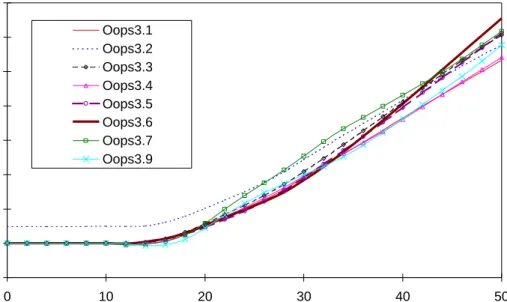
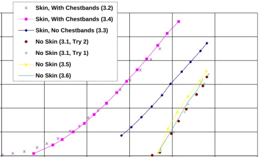
dummy response is crucial in the usefulness of such research, a preliminary investigation was performed to determine the repeatability of response of the dummy ribs under quasistatic deformation under various conditions. For these tests, a 2.54-cm diameter pin was screwed into the steering column load cell, temporarily replacing the steering wheel and air bag module. The pin was pressed into the horizontal and vertical center of the dummy sternum using the hydraulic cylinders supporting the test fixture. Displacements of the pin were measured using the Faro arm measurement device at the steering wheel fixture reference location. Results for selected tests are plotted in Figure 12.
The tests with skin performed before OOPS3.2 – OOPS3.4 showed very similar slopes for all cases. The thickness of the chestbands and associated tape resulted in an approximately 10 mm offset before OOPS3.2 and OOPS3.4. Testing delays between the three tests with skin were approximately an hour and approximately 24 hours. In addition, the deformations performed without skin both before testing started and after tests OOPS3.1, OOPS3.5, and OOPS3.6 all show similar force/deflection slopes. The delay between the earliest and latest tests was approximately 36 hours. Subsequent tests resulted in negligible variation of slope from those seen below. This indicates a negligible change in occupant rib stiffness over the quasistatic conditions tested and suggests that subject rib repeatability is acceptable under the test conditions used. 0 100 200 300 400 500 600 0 10 20 30 40 50 60
Deflection from Reference Location (mm)
Force (N)
Skin, With Chestbands (3.2) Skin, With Chestbands (3.4) Skin, No Chestbands (3.3) No Skin (3.1, Try 2) No Skin (3.1, Try 1) No Skin (3.5) No Skin (3.6)
Figure 12: Force/Deflection Profiles for Mid-Thorax Quasistatic Compression with 2.54 cm Diameter Pin
performance. In Section 3.3.2, the dynamic viscous response of the dummy thorax is investigated using V*C data from each thoracic instrumentation.
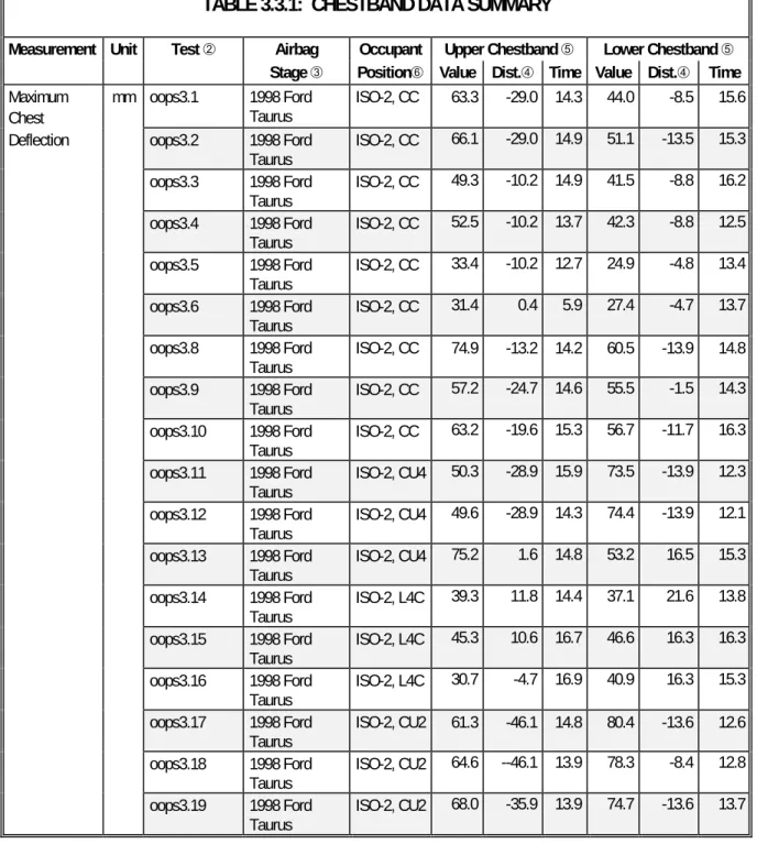
TABLE 3.3.1: CHESTBAND DATA SUMMARY
Measurement Unit Test Á Airbag Occupant Upper Chestband Ä Lower Chestband Ä
Stage  PositionŠValue Dist.à Time Value Dist.à Time Maximum
Chest
mm oops3.1 1998 Ford Taurus
ISO-2, CC 63.3 -29.0 14.3 44.0 -8.5 15.6 Deflection oops3.2 1998 Ford
Taurus ISO-2, CC 66.1 -29.0 14.9 51.1 -13.5 15.3 oops3.3 1998 Ford Taurus ISO-2, CC 49.3 -10.2 14.9 41.5 -8.8 16.2 oops3.4 1998 Ford Taurus ISO-2, CC 52.5 -10.2 13.7 42.3 -8.8 12.5 oops3.5 1998 Ford Taurus ISO-2, CC 33.4 -10.2 12.7 24.9 -4.8 13.4 oops3.6 1998 Ford Taurus ISO-2, CC 31.4 0.4 5.9 27.4 -4.7 13.7 oops3.8 1998 Ford Taurus ISO-2, CC 74.9 -13.2 14.2 60.5 -13.9 14.8 oops3.9 1998 Ford Taurus ISO-2, CC 57.2 -24.7 14.6 55.5 -1.5 14.3 oops3.10 1998 Ford Taurus ISO-2, CC 63.2 -19.6 15.3 56.7 -11.7 16.3 oops3.11 1998 Ford
Taurus ISO-2, CU4
50.3 -28.9 15.9 73.5 -13.9 12.3 oops3.12 1998 Ford
Taurus ISO-2, CU4
49.6 -28.9 14.3 74.4 -13.9 12.1 oops3.13 1998 Ford Taurus ISO-2, CU4 75.2 1.6 14.8 53.2 16.5 15.3 oops3.14 1998 Ford Taurus ISO-2, L4C 39.3 11.8 14.4 37.1 21.6 13.8 oops3.15 1998 Ford Taurus ISO-2, L4C 45.3 10.6 16.7 46.6 16.3 16.3 oops3.16 1998 Ford Taurus ISO-2, L4C 30.7 -4.7 16.9 40.9 16.3 15.3 oops3.17 1998 Ford
Taurus ISO-2, CU2 61.3 -46.1 14.8 80.4 -13.6 12.6 oops3.18 1998 Ford Taurus ISO-2, CU2 64.6 --46.1 13.9 78.3 -8.4 12.8 oops3.19 1998 Ford Taurus ISO-2, CU2 68.0 -35.9 13.9 74.7 -13.6 13.7
Maximum Sternum
mm oops3.1 1998 Ford Taurus
ISO-2, CC 59.3 0 14.2 43.5 0 15.3
Deflection oops3.2 1998 Ford Taurus ISO-2, CC 60.1 0 14.6 50.3 0 15.3 oops3.3 1998 Ford Taurus ISO-2, CC 48.5 0 15.0 40.9 0 16.0 oops3.4 1998 Ford Taurus ISO-2, CC 51.7 0 13.6 41.8 0 12.9 oops3.5 1998 Ford Taurus ISO-2, CC 33.1 0 13.2 24.8 0 13.5 oops3.6 1998 Ford Taurus ISO-2, CC 27.5 0 12.7 26.9 0 13.9 oops3.8 1998 Ford Taurus ISO-2, CC 74.1 0 14.3 59.4 0 15.0 oops3.9 1998 Ford Taurus ISO-2, CC 54.9 0 14.5 55.4 0 14.2 oops3.10 1998 Ford Taurus ISO-2, CC 59.4 0 15.6 56.0 0 15.7 oops3.11 1998 Ford
Taurus ISO-2, CU4 44.5 0 15.9 71.9 0 12.4
oops3.12 1998 Ford Taurus ISO-2, CU4 46.3 0 19.7 72.7 0 12.2 oops3.13 1998 Ford Taurus ISO-2, CU4 74.8 0 14.7 51.3 0 15.4 oops3.14 1998 Ford Taurus ISO-2, L4C 38.3 0 14.0 34.2 0 14.3 oops3.15 1998 Ford Taurus ISO-2, L4C 44.4 0 16.4 45.4 0 16.1 oops3.16 1998 Ford Taurus ISO-2, L4C 30.1 0 17.0 38.9 0 15.6 oops3.17 1998 Ford Taurus ISO-2, CU2 52.3 0 14.9 79.0 0 12.7 oops3.18 1998 Ford Taurus ISO-2, CU2 56.6 0 12.4 77.6 0 12.6 oops3.19 1998 Ford Taurus ISO-2, CU2 60.8 0 13.7 73.8 0 13.7
Value Time Value Time Sternal V*C m/s oops3.1 1998 Ford Taurus ISO-2, CC 1.3 10.7 0.8 9.9 oops3.2 1998 Ford Taurus ISO-2, CC 1.1 9.0 1.0 13.0 oops3.3 1998 Ford Taurus ISO-2, CC 1.0 8.7 0.8 8.9 oops3.4 1998 Ford Taurus ISO-2, CC 1.3 9.9 0.9 9.0 oops3.5 1998 Ford Taurus ISO-2, CC 1.3 5.9 0.4 7.5 oops3.6 1998 Ford Taurus ISO-2, CC 1.2 5.7 1.0 7.3 oops3.8 1998 Ford Taurus ISO-2, CC 3.5 9.3 2.4 10.6 oops3.9 1998 Ford Taurus ISO-2, CC 2.7 8.6 1.6 12.0 oops3.10 1998 Ford Taurus ISO-2, CC 1.8 8.9 2.1 13.1 oops3.11 1998 Ford Taurus ISO-2, CU4 1.3 11.1 4.1 11.2 oops3.12 1998 Ford Taurus ISO-2, CU4 1.9 12.7 4.6 10.8 oops3.13 1998 Ford Taurus ISO-2, CU4 3.3 11.5 1.2 11.8 oops3.14 1998 Ford Taurus ISO-2, L4C 1.0 9.9 0.7 10.8 oops3.15 1998 Ford Taurus ISO-2, L4C 1.5 8.1 1.7 9.4 oops3.16 1998 Ford Taurus ISO-2, L4C 0.7 8.1 1.5 14.2 oops3.17 1998 Ford Taurus ISO-2, CU2 1.5 11.1 5.2 10.9 oops3.18 1998 Ford Taurus ISO-2, CU2 1.8 11.0 4.6 10.9 oops3.19 1998 Ford
Taurus ISO-2, CU2
Value Time Value Time Maximum Sternum m/s oops3.1 1998 Ford Taurus ISO-2, CC 14.9 6.0 9.7 8.4
Velocity oops3.2 1998 Ford
Taurus ISO-2, CC 15.4 5.7 9.3 8.5 oops3.3 1998 Ford Taurus ISO-2, CC 11.0 5.8 11.0 7.7 oops3.4 1998 Ford Taurus ISO-2, CC 10.7 5.7 11.6 7.6 oops3.5 1998 Ford Taurus ISO-2, CC 19.5 5.7 9.6 7.2 oops3.6 1998 Ford Taurus ISO-2, CC 18.9 5.5 15.9 7.1 oops3.8 1998 Ford Taurus ISO-2, CC 20.2 9.0 19.8 9.9 oops3.9 1998 Ford Taurus ISO-2, CC 18.5 8.4 11.6 8.4 oops3.10 1998 Ford Taurus ISO-2, CC 14.4 8.8 12.0 12.9 oops3.11 1998 Ford Taurus ISO-2, CU4 14.6 10.9 15.5 10.9 oops3.12 1998 Ford Taurus ISO-2, CU4 12.9 12.5 18.1 10.6 oops3.13 1998 Ford
Taurus ISO-2, CU4
23.2 6.1 12.1 9.7 oops3.14 1998 Ford Taurus ISO-2, L4C 11.6 4.9 8.6 9.7 oops3.15 1998 Ford Taurus ISO-2, L4C 12.