Linear Scan Register Allocation on SSA Form
Christian Wimmer
Michael Franz
Department of Computer Science University of California, Irvine
{cwimmer, franz}@uci.edu
Abstract
The linear scan algorithm for register allocation provides a good register assignment with a low compilation overhead and is thus frequently used for just-in-time compilers. Although most of these compilers use static single assignment (SSA) form, the algorithm has not yet been applied on SSA form, i.e., SSA form is usually deconstructed before register allocation. However, the structural properties of SSA form can be used to simplify the algorithm.
With only one definition per variable, lifetime intervals (the main data structure) can be constructed without data flow analy-sis. During allocation, some tests of interval intersection can be skipped because SSA form guarantees non-intersection. Finally, deconstruction of SSA form after register allocation can be inte-grated into the resolution phase of the register allocator without much additional code.
We modified the linear scan register allocator of the Java HotSpotTM client compiler so that it operates on SSA form. The evaluation shows that our simpler and faster version generates equally good or slightly better machine code.
Categories and Subject Descriptors D.3.4 [Programming Lan-guages]: Processors—Compilers, Optimization, Code generation General Terms Algorithms, Languages, Performance
Keywords Java, just-in-time compilation, register allocation, lin-ear scan, SSA form, lifetime analysis, SSA form deconstruction
1.
Introduction
Register allocation, i.e., the task of assigning processor registers to local variables and temporary values, is one of the most im-portant compiler optimizations. A vast amount of research has led to algorithms ranging from simple and fast heuristics to optimal algorithms with exponential time complexity. Because the prob-lem is known to be NP-complete [8], algorithms must balance the time necessary for allocation against the resulting code quality. Two common algorithms in modern compilers are graph coloring (see for example [5, 8]), which is suitable when compilation time is not a major concern, and linear scan [22, 28], which is faster and there-fore frequently used for just-in-time compilers where compilation time adds to run time.
c
ACM, 2010. This is the author’s version of the work. It is posted here by permission of ACM for your personal use. Not for redistribution. The definitive version was published in the Proceedings of the International Symposium on Code Generation and Optimization, pp. 170–179.
CGO’10, April 24–28, 2010, Toronto, Ontario, Canada. http://doi.acm.org/10.1145/1772954.1772979
Static single assignment (SSA) form [9] is a type of interme-diate representation that simplifies many compiler optimizations. All variables have only a single point of definition. At control flow joins, phi functions are used to merge different variables of the pre-decessor blocks. Because processors cannot execute phi functions, it is necessary to replace them with move instructions during code generation (SSA form deconstruction).
Traditionally, SSA form deconstruction was performed before register allocation. Only recently has it been observed that register allocation on SSA form has several advantages due to additional guarantees on variable lifetime. Lifetime information is essential for register allocation because two variables that interfere, i.e., that are live at the same time, must not have the same register assigned. The interference graph of a program in SSA form is chordal (every cycle with four or more edges has an edge connecting two vertices of the cycle, leading to a triangulated structure).
Many graph algorithms are simpler on chordal graphs, e.g., graph coloring can be performed in polynomial time. These proper-ties were used to simplify register allocators based on graph color-ing [14]. When the maximum register pressure is below or equal to the number of available registers, allocation is guaranteed to suc-ceed. This allows to split the algorithms for spilling and register assignment. Traditionally, spilling and register assignment were in-terleaved, i.e., a variable was spilled when the graph turned out to be not colorable. This led to a time-consuming repeated execution of the graph coloring algorithm.
This paper explores the impact of SSA form on linear scan regis-ter allocation. The lifetime inregis-tervals, which are the basic data struc-ture of the algorithm, are easier to construct and have a simpler structure. Additionally, infrastructure already present in the linear scan algorithm can be used to perform SSA form deconstruction after register allocation, thus making a separate SSA form decon-struction algorithm unnecessary.
Our implementation for the Java HotSpotTM client compiler shows that SSA form leads to a simpler and faster linear scan al-gorithm. It generates the same or even better code than the current product version that deconstructs SSA form before register alloca-tion. In summary, this paper contributes the following:
• We show how SSA form affects the lifetime intervals used by the linear scan algorithm.
• We present an algorithm for constructing lifetime intervals that does not require data flow analysis. The algorithm can also be adapted to construct the interference graph for graph coloring register allocation.
• We show how to use SSA form properties during allocation. • We integrate SSA form deconstruction into the resolution phase
of the linear scan algorithm.
• We evaluate the algorithm using the Java HotSpotTM client compiler.
LIR Construction
Lifetime Analysis
Linear Scan Algorithm
Resolution
LIR not in SSA Form with Virtual Registers
LIR not in SSA Form with Physical Registers
Requires a Data Flow Analysis
Splitting and Spilling of Lifetime Intervals
Lifetime Intervals with Lifetime Holes
Includes SSA Form Deconstruction
Registers Assigned to Lifetime Intervals
Figure 1. Linear scan register allocation not on SSA form.
2.
Overview
The linear scan algorithm is used for register allocation in many major compilers, e.g., the client compiler of the Java HotSpotTM VM [11, 16], the optimizing compiler of the Jikes RVM [1], and the compiler of the Low Level Virtual Machine (LLVM) [17]. All implementations use different heuristics to make the algorithm fast and to produce good machine code, but none operate on SSA form. However, all three compilers use SSA form for global optimiza-tions, so all provide the necessary infrastructure for SSA-form-based register allocation.
We use our previous work on linear scan register allocation for the Java HotSpotTM client compiler [30] as the baseline for this study. The client compiler is a production-quality just-in-time compiler and thus highly tuned both for compilation speed and code quality. Its source code is available as open source from the OpenJDK project [27]. Implementation details of the linear scan register allocator are available from [29].
The front end of the client compiler first parses Java byte-codes [18] and constructs the high-level intermediate represen-tation (HIR), which is in SSA form. Several optimizations are performed on the HIR, including constant folding, global value numbering, method inlining, and null-check elimination. The back end translates the HIR into the low-level intermediate representa-tion (LIR). It is not in SSA form in the current product version, so the translation includes SSA form deconstruction.
The LIR is register based. At first, most operands are virtual reg-isters. Only register constraints of the target architecture are mod-eled using physical registers in the initial LIR. Before register al-location, the control flow graph is flattened to a list of blocks. The register allocator replaces all virtual registers with physical regis-ters, thereby inserting code for spilling registers to the stack if more values are simultaneously live than registers are available. This is accomplished by splitting lifetime intervals, which requires a reso-lution phase after register allocation to insert move instructions at control flow edges. There is no distinction between local variables and temporary values, they are all uniformly represented as virtual registers. After register allocation, each LIR operation is translated to one or more machine instructions, whereby most LIR operations require only one machine instruction. Figure 1 shows the compiler phases of the current product version that are relevant for register allocation.
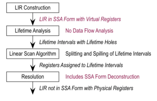
Figure 2 illustrates the changes necessary for SSA-form-based register allocation. SSA form is no longer deconstructed before reg-ister allocation. Additionally, construction of lifetime intervals is simplified because no data flow analysis is necessary. The main linear scan algorithm remains mostly unchanged, but still benefits from some SSA form properties. If SSA form is no longer required after register allocation, as in our implementation, SSA form
de-Lifetime Analysis
Linear Scan Algorithm
Resolution
LIR in SSA Form with Virtual Registers
LIR not in SSA Form with Physical Registers
No Data Flow Analysis
Splitting and Spilling of Lifetime Intervals
Lifetime Intervals with Lifetime Holes
Includes SSA Form Deconstruction LIR Construction
Registers Assigned to Lifetime Intervals
Figure 2. Linear scan register allocation on SSA form.
construction can be easily integrated into the already existing reso-lution phase.
Moving out of SSA form after register allocation is reasonable because register allocation is usually one of the last global opti-mizations, so SSA form would not be beneficial afterwards. How-ever, it would also be possible to maintain SSA form, which re-quires the insertion of new phi functions for variables whose life-time intervals were split. The standard algorithm for SSA form con-struction [9] can be used for this.
3.
Lifetime Intervals and SSA Form
Our variant of the linear scan algorithm requires exact lifetime information: The lifetime interval of a virtual register must cover all parts where this register is needed, with lifetime holes in between. Lifetime holes occur because the control flow graph is reduced to a list of blocks before register allocation. If a register flows into an else-block, but not into the correspondingif-block, the lifetime interval has a hole for theif-block. In contrast, a register defined before a loop and used inside the loop must be live in all blocks of the loop, even blocks after the last use.
The lifetime intervals resulting from phi functions have char-acteristic patterns. When SSA form is deconstructed before regis-ter allocation, move instructions are inserted at the end of a phi function’s predecessor blocks. This leads to a lifetime interval with multiple definition points and lifetime holes before these defini-tions. SSA form deconstruction inserts the moves in a certain order. While there are some constraints for the order in cases where the same register is both used and defined by phi functions of the same block, the order is mostly arbitrary.
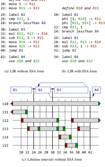
Figure 3(c) shows the lifetime intervals for the LIR fragment (computing the factorial of a number) shown in Figure 3(a). Four blocksB1toB4use six virtual registersR10toR15. Assume that R10andR11are defined inB1, and thatR10andR12are used inB4. R10represents a long-living value that is infrequently used but still alive, e.g., thethispointer of a Java method. The LIR operations 20to42(numbers are incremented by two for technical reasons) are arithmetic and control flow operations that use up to two input operands (either virtual registers or constants) and define up to one output operand (a virtual register).
The registersR12andR13represent the original phi functions, and the registersR14andR15represent the new values assigned to the phi functions at the end of the loop. Therefore,R12andR13 have the characteristic lifetime intervalsi12andi13in Figure 3(c) (virtual registers and intervals use matching numbers). Intervali12 is defined by the operations20and36. Because the definition at36 overwrites the previous value without using it, there is a lifetime hole before this operation, starting at the last use at operation32. The intervalsi12andi13have a similar structure, onlyi12
ex-!!!!!"#$%"&'()&*%!&'(( "#$!%&'(!)!*+!,)" ""$!%&'(!,))!*+! ,)-".$!/01(/!2" "3$!4%5!,)-6!) "7$!18094:!/(;;<:09!2. -#$!/01(/! 2--"$!%=/!,)"6!,)-!*+!,). -.$!;=1!,)-6!)!*+!,)> -3$!%&'(!,).!*+!,)" -7$!%&'(!,)>!*+! ,)-.#$!?=%5!2" ."$!/01(/!2. !!!!+,"&'()&*%!&
'(-(a) LIR without SSA form
!!!!!"#$%"&'()&*%!&'(( "#$!%&'(%!)" !!!!*+,!-./!0.12!34!0." !!!!*+,!-0../!0.52!34!0.6 ""$!78*!0.6/!. "1$!'9&:7+!%(;;<+&:!)1 "=$!%&'(%!)6 ">$!8?%!0."/!0.6!34!0.1 6#$!;?'!0.6/!.!34!0.5 6"$!@?8*!)" 61$!%&'(%!)1 !!!!+,"&'()&*%!&
'(-(b) LIR with SSA form
!"# !"" !"$ !"% !"& !"'
$# $$ $& $( $) %# %$ %& %( %) &# &$
*$
*" *% *&
(c) Lifetime intervals without SSA form
!"# !"" !"$ !"% !"& !"' $# $$ $& $( $) %# %$ %& *$ *" *% *&
(d) Lifetime intervals with SSA form Figure 3. Example of LIR and lifetime intervals.
tends after operation42because R12is used somewhere later in blockB4. Note that although the intervali12is contiguous fromB3 toB4, there is no direct control flow possible between these two blocks.
Building lifetime intervals directly from LIR in SSA form changes the pattern of the intervals. All phi functions at the be-ginning of a block have parallel copy semantics, i.e., they are not
ordered. All phi functions together specify a permutation of regis-ters and not a list of copies. Therefore, it would be counterproduc-tive to assign individual operation numbers to them; we just attach them to the block label. The lifetime interval for the virtual regis-ter defined by a phi function starts directly at the beginning of the block. The lifetime intervals for the virtual registers used by a phi function end at the end of the corresponding predecessor blocks (as long as the virtual registers are not used by other operations after the phi function).
Figure 3(b) and Figure 3(d) show the LIR and the lifetime inter-vals of our example when using SSA form. The two phi functions of blockB2are attached to operation20. Therefore, the lifetime intervalsi12andi13both start at position20. The linear scan al-gorithm, which processes intervals ordered by their start position, can freely decide which interval to process first, i.e., in cases of high register pressure it can better decide which intervals to spill at this position. Intervali13no longer has a lifetime hole. Inter-vali12still requires a lifetime hole because the value is live at the beginning ofB4but not at the end ofB3, however the lifetime hole ends at a block boundary.
These patterns of lifetime intervals show two advantages when performing linear scan register allocation on SSA form: (1) No artificial order is imposed for moves resulting from phi functions, resulting in more freedom for the register allocator. (2) The lifetime intervals for phi functions have fewer lifetime holes, leading to less state changes of the intervals during allocation.
Note that both with and without SSA form, no coalescing of non-overlapping lifetime intervals is performed. Without SSA form, i.e., in the current product version, it would be too slow and complicated. With SSA form, it is not allowed because it would violate SSA form. In both cases, register hints are used as a lightweight replacement. Intervals that should be assigned the same physical register are connected via a register hint. The linear scan allocator honors this hint if possible, but is still allowed to assign different registers. The source and target of a move are connected with such a hint. With SSA form, the input and result operands of a phi function are also connected. In our example, the inter-valsi11,i13, andi15are connected, as well as the intervalsi12 andi14. In this small example, the register hints lead to machine code without any move instructions, both with and without SSA form.
4.
Lifetime Analysis
Traditionally, lifetime information has been computed using an iterative data flow analysis that is repeated until a stable fixed-point is reached. Using properties guaranteed by SSA form in combination with a special block order allows us to eliminate the data flow analysis. With SSA form, each virtual register has a single point of definition. This definition is “before” all uses, i.e., the definition dominates all uses [7]. If the definition and a use are in different blocks, this means that the block of the definition is a dominator of the block of the use.
The linear scan algorithm does not operate on a structured con-trol flow graph, but on a linear list of blocks. The block order has a high impact on the quality and speed of linear scan: A good block order leads to short lifetime intervals with few holes. Our block or-der guarantees the following properties: First, all predecessors of a block are located before this block, with the exception of back-ward edges of loops. This implies that all dominators of a block are located before this block. Secondly, all blocks that are part of the same loop are contiguous, i.e., there is no non-loop block between two loop blocks. Even though the current product version of the client compiler’s linear scan algorithm could operate on any block order, this order turned out to be best.
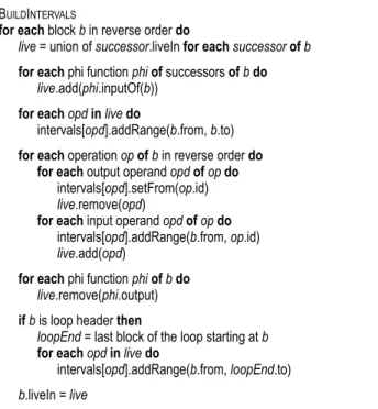
BUILDINTERVALS
for each block b in reverse order do
live = union of successor.liveIn for eachsuccessorofb
for each phi function phiof successors ofbdo
live.add(phi.inputOf(b))
for eachopdinlivedo
intervals[opd].addRange(b.from, b.to)
for each operation opofb in reverse order do for each output operand opdofopdo
intervals[opd].setFrom(op.id)
live.remove(opd)
for each input operand opdofopdo
intervals[opd].addRange(b.from, op.id)
live.add(opd)
for each phi function phiofbdo
live.remove(phi.output)
ifb is loop header then
loopEnd = last block of the loop starting at b
for eachopdinlivedo
intervals[opd].addRange(b.from, loopEnd.to)
b.liveIn = live
Figure 4. Algorithm for construction of lifetime intervals.
4.1 Algorithm
Input of the algorithm:
1. Intermediate representation in SSA form. An operation has input and output operands. Only virtual register operands are relevant for the algorithm.
2. A linear block order where all dominators of a block are before this block, and where all blocks belonging to the same loop are contiguous. All operations of all blocks are numbered using this order.
Output of the algorithm: One lifetime interval for each virtual register, covering operation numbers where this register is alive, and with lifetime holes in between. Thus, a lifetime interval con-sists of one or more ranges of operation numbers.
Figure 4 shows the algorithm. In addition to the input and output data structures, it requires a set of virtual registers, called liveIn, for each block. It is used to propagate the virtual registers that are live at the beginning of a block to the block’s predecessors. The algorithm requires one linear iteration of all blocks and all operations of each block. The iteration is in reverse order so that all uses of a virtual register are seen before its definition. Therefore, successors of a block are processed before this block. Only for loops, the loop header (which is a successor of the loop end) cannot be processed before the loop end, so loops are handled as a special case.
The initial set of virtual registers that are live at the end of block b is the union of all registers live at the beginning of the successors of b. Additionally, phi functions of the successors con-tribute to the initial live set. For each phi function, the input operand corresponding to b is added to the live set. For each live register, an initial live range covering the entire block is added. This live range might be shortened later if the definition of the register is encoun-tered.
Next, all operations of b are processed in reverse order. An out-put operand, i.e., a definition of a virtual register, shortens the cur-rent range of the register’s lifetime interval; the start position of the first range is set to the current operation. Additionally, the register
is removed from the set of live registers. An input operand, i.e., a use of a virtual register, adds a new range to the lifetime interval (the new range is merged if an overlapping range is present). The new live range starts at the beginning of the block, and again might be shortened later. Additionally, the register is added to the set of live registers.
Phi functions are not processed during this iteration of opera-tions, instead they are iterated separately. Because the live range of a phi function starts at the beginning of the block, it is not nec-essary to shorten the range for its output operand. The operand is only removed from the set of live registers. The input operands of the phi function are not handled here, because this is done indepen-dently when the different predecessors are processed. Thus, neither an input operand nor the output operand of a phi function is live at the beginning of the phi function’s block.
The steps described so far are sufficient to create the lifetime intervals for methods without loops. With loops, the intervals are incomplete: When a loop’s end block is processed, the loop header has not been processed, so its liveIn set is still empty. Therefore, registers that are alive for the entire loop are missing at this time. These registers are known at the time the loop header is processed: All registers live at the beginning of the loop header must be live for the entire loop, because they are defined before the loop and used inside or after it. Using the property that all blocks of a loop are contiguous in the linear block order, it is sufficient to add one live range, spanning the entire loop, for each register that is live at the beginning of the loop header.
Finally, the current set of live registers is saved in the liveIn field of the block. Note that liveIn is only a temporary data structure. Be-cause the loop handling adds live ranges but does not update liveIn sets, they remain incomplete. If the liveIn sets were needed by a later compiler phase, a fixup would also be necessary. However, we do not need them later.
4.2 Example
The example shown in Figure 3(b) and Figure 3(d) uses the virtual registersR10 toR15. The algorithm processes the blocks in the orderB4,B3,B2, andB1. At the beginning ofB4, the registersR10 andR12are live and therefore in the liveIn set ofB4. The live ranges of these values forB4have been added.
The first complete block of the example isB3. The liveIn set of its successorB2is empty sinceB2has not been processed yet.B2 has two phi functions, whose operands relevant forB3areR14and R15. They are added to the live set, and the initial ranges spanning the entire blockB3are added. When the definitions ofR14andR15 are encountered at operation28and30, respectively, the ranges are shortened to their final starting points. Ranges forR12andR13are added, and these two registers are in the liveIn set ofB3. Note that the live range ofR10forB3is not yet present.
The initial live set ofB2is the union of liveIn ofB3and B4, i.e., it containsR10,R12, andR13. These three registers are live for the entire block. BecauseR12andR13are defined by phi functions ofB3, they are removed from the live set when the phi functions are processed, soR10is the only register live at the beginning of B2. BecauseB2is a loop header, the special handling for loops is performed: The loopEnd block isB3, so a live range spanning from the beginning ofB2to the end ofB3is added to the interval ofR10. This live range is merged with the existing one, resulting inR10 being live contiguously.
Finally,B1is processed. The registerR10is initially live be-cause it is in the liveIn set of the successorB2, andR11is live be-cause it is the relevant operand for a phi function. Live ranges are added to the intervals of these two registers. The remaining han-dling ofB1is outside the scope of this example. Figure 3(d) shows the final intervals for the example.
B1 B3 B2 B4 B5 B6 B7 use R10 define R10 and R11 use R11
Figure 5. CFG with irreducible loop.
4.3 Irreducible Control Flow
The algorithm presented in the previous sections does not work properly for irreducible loops, i.e., for loops with multiple en-try points. Java bytecodes are usually created from structured lan-guages like Java, so irreducible loops do not occur normally. How-ever, since Java bytecodes themselves are unstructured, they are possible with handcrafted bytecodes.
Figure 5 shows such a loop: it can be entered via the blocksB4 andB5. The figure shows definitions and uses of the registersR10 andR11. ForR11, the algorithm works correctly: the register is in the liveIn sets ofB4andB5 and thus the liveness information is correctly propagated to the blocksB3andB2. However, the register R10is only in the liveIn set ofB4, since it was not yet regarded as live whenB5was processed. It is therefore not considered live inB2, which is erroneous. There are two solutions to handle this problem:
1. Perform a precise loop analysis for irreducible loops that cor-rectly detects all entry blocks. Irreducible loops must be con-tiguous, i.e., all non-loop blocks leading to a loop entry must be placed before the first loop entry. After all blocks of a loop have been processed by our algorithm, the liveIn of all loop headers must be set to the union of the registers flowing into the loop. This solution requires a more complicated loop analysis as well as modifications to our algorithm.
2. Make sure that no values flow into an irreducible loop, i.e., that the liveIn set of all loop headers is empty. This can be achieved by inserting phi functions at the loop headers for variables that are not modified inside the loop. These phi functions serve as explicit definitions of virtual registers inside the loop.
We use the second solution because the necessary precondi-tions, the additional phi funcprecondi-tions, are already fulfilled by the client compiler. The client compiler uses a conservative SSA form con-struction algorithm where phi functions are created when they might be needed, and unnecessary phi functions are eliminated later. However, they are not eliminated for irreducible loops be-cause this would complicate the elimination algorithm and the ad-ditional phi functions are not harmful. This is a good example how the conservative handling of corner cases in multiple parts of the compiler play nicely together.
One special case where irreducible loops occur in practice are methods compiled for on-stack replacement (OSR) [10, 15]. In order to switch from the interpreter to compiled code in the middle of a long-running loop, the method is compiled with a special entry point that jumps directly into the middle of the method. This leads to a loop with two entry points. However, since values flowing into
TRYALLOCATEFREEREG
set freeUntilPos of all physical registers to maxInt for each interval it in activedo
freeUntilPos[it.reg] = 0
for each interval it in inactive intersecting with currentdo freeUntilPos[it.reg] = next intersection of it with current reg = register with highest freeUntilPos
...
ALLOCATEBLOCKEDREG
set nextUsePos of all physical registers to maxInt for each interval it in activedo
nextUsePos[it.reg] = next use of it after start of current for each interval it in inactive intersecting with currentdo
nextUsePos[it.reg] = next use of it after start of current reg = register with highest nextUsePos
...
Figure 6. Algorithm for register selection (from [30]).
the loop from the normal pre-loop code and from the OSR entry point are completely disjoint, phi functions must always be present. Therefore, OSR methods need no special handling in our register allocator.
4.4 Analogy with Interference Graphs
Our algorithm to build lifetime intervals can be modified to build the interference graph for a graph coloring register allocator in a single pass over the operations. The live sets are managed in the same way. Whenever a definition of a register is encountered, this register interferes with all registers that are currently in the live set. It is sufficient to look at the definition points because SSA form guarantees that two registers that interfere somewhere also interfere at the definition of one of the registers [7]. Again, a special handling is necessary at the loop header: A register live at the loop header interferes with all registers defined inside the loop. It is straightforward to collect all registers defined inside the loop during the iteration of the operations, and to add the interference edges with all registers live at the loop header.
5.
Linear Scan Algorithm
The main linear scan algorithm needs no modifications to work on SSA form. Because the algorithm is extensively described in [30], we give only a short summary here. It processes the lifetime in-tervals sorted by their start position and assigns a register or stack slot to each interval. For this, four sets of intervals are managed: unhandled contains the intervals that start after the current position and are therefore not yet of interest; active contains the intervals that are live at the current position; inactive contains the intervals that start before and end after the current position, but that have a lifetime hole at the current position; and handled contains the inter-vals that end before the current position and are therefore no longer of interest. An interval can switch several times between active and inactive until it is finally moved to handled. If a register is not avail-able for the entire lifetime of an interval, this or another interval is split and spilled to a stack slot, leading to new intervals added to the unhandled set during the run of the algorithm. However, the al-gorithm never backtracks, i.e., all added intervals always start after the current position.
The main part of the linear scan algorithm is the selection of a free register if one is available, or the selection of an interval to be split and spilled if no register is available. Figure 6 shows fragments of these two algorithms. While the original linear scan algorithm [22] was designed to have linear runtime complexity,
RESOLVE
for each control flow edge from predecessor to successordo for each interval it live at begin of successordo
ifit starts at begin of successorthen phi = phi function defining it opd = phi.inputOf(predecessor)
ifopd is a constant then moveFrom = opd else
moveFrom = location of intervals[opd] at end of predecessor else
moveFrom = location of it at end of predecessor moveTo = location of it at begin of successor ifmoveFrom ≠ moveTothen
mapping.add(moveFrom, moveTo)
mapping.orderAndInsertMoves()
Figure 7. Algorithm for resolution and SSA form deconstruction.
the extensions to support lifetime holes and interval splitting [28, 30] introduced non-linear parts. Two of them are highlighted in Figure 6 where the set of inactive intervals is iterated. The set can contain an arbitrary number of intervals since it is not bound by the number of physical registers. Testing the current interval for intersection with all of them can therefore be expensive.
When the lifetime intervals are created from code in SSA form, this test is not necessary anymore: All intervals in inactive start before the current interval, so they do not intersect with the current interval at their definition. They are inactive and thus have a lifetime hole at the current position, so they do not intersect with the current interval at its definition. SSA form therefore guarantees that they never intersect [7], making the entire loop that tests for intersection unnecessary.
Unfortunately, splitting of intervals leads to intervals that no longer adhere to the SSA form properties because it destroys SSA form. Therefore, the intersection test cannot be omitted completely; it must be performed if the current interval has been split off from another interval. In summary, the highlighted parts of Figure 6 can be guarded by a check whether current is the result of an interval split, and need not be executed otherwise. For our set of Java benchmarks, this still saves 59% to 79% of all intersection tests.
6.
Resolution and SSA Form Deconstruction
Linear scan register allocation with splitting of lifetime intervals requires a resolution phase after the actual allocation. Because the control flow graph is reduced to a list of blocks, control flow is possible between blocks that are not adjacent in the list. When the location of an interval is different at the end of the predecessor and at the start of the successor, a move instruction must be inserted to resolve the conflict. The resolving moves for a control flow edge have the same semantics as the moves necessary to resolve phi functions: They must be treated as parallel copies, i.e., a mapping from source to target locations. The only difference is that moves resulting from interval splitting originate from a single interval, while moves resulting from phi functions have different intervals for the source and the target. In both cases, the moves must be ordered properly so that registers holding incoming values are not overwritten with outgoing values.Adding SSA form deconstruction requires only small exten-sions to the existing resolution algorithm. Figure 7 shows the entire algorithm. It visits every edge of the control flow graph, connect-ing a block predecessor with a block successor, and iterates all intervals that are live at the beginning of successor. The algorithm compares the location of the interval at the end of predecessor and
!"# !"$ !"% !"& '" '$ ()* (+* (,*
Interval !"# from -% to -&: ./0(1'"23(,* Interval !"# from -$ to -&: no move necessary
Phi Function145"%678235"&1 from -$ to -&: no move necessary Phi Function14765"$8235"&1 from -% to -&:1./0(1'$23(+* (,* -$ -" -% -& (+*
Figure 8. Example for resolution and SSA form deconstruction.
the beginning of successor. If they are different, a move operation is inserted. Because all moves must be ordered properly, they are first added to a mapping and then ordered and inserted afterwards. This part of the algorithm is not shown because it requires no SSA form specific changes.
Intervals of phi functions of successor are live at the beginning of successor, but not at the end of predecessor. SSA form proper-ties and the block order guarantee that these intervals start at the beginning of successor. This guarantee allows for a simple check whether an interval is defined by a phi function. Three steps are necessary to compute the source operand of the move operation that resolves the phi function:
1. the phi function that defined the interval is retrieved,
2. the input operand of the phi function that belongs to block predecessor is retrieved, and
3. the interval of this operand is used to add the move operation. If the input operand is a constant, no interval is present because constants can be directly used as the source of move operations.
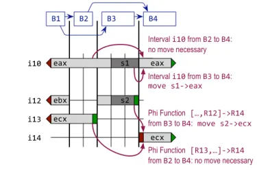
Figure 8 shows an example for resolution that is necessary at the edges to blockB4. BlockB4has two predecessors,B2andB3. Two intervals are live at the beginning ofB4:i10andi14. Intervali10 is defined before the beginning ofB4(actually it is defined outside the scope of our example). During register allocation,i10was split twice. At first, the location is the registereax. In the middle of blockB3, it was spilled and thus the location changes to stack slot s1. At the beginning of blockB4, it is reloaded to registereax.
Interval i14(with the assigned registerecx) is defined at the beginning of blockB4by a phi function. Assume that the operands of the phi function areR12(when coming from blockB3) andR13 (when coming from blockB2). The according intervals are i12 andi13, respectively. Intervali12was split in blockB3and thus changes the location there from registerebxto stack slots2, while intervali13is always in register ecx. The scenario depicted is realistic in that a method call inside blockB3requires all intervals to be spilled.
First, we look at the control flow edge from B2 to B4. The location of intervali10at the end ofB2iseax, and at the beginning ofB4is alsoeax. Thus, no resolving move is necessary. Interval i14starts atB4. Accessing the corresponding phi function, its input operand for blockB2, and the interval for this operand, yields the intervali13. Because the location ofi13andi14are bothecx, again no resolving move is necessary, and the mapping for this control flow edge remains empty.
Baseline Baseline Baseline Baseline
SPECjvm2008 SPECjbb2005 DaCapo SciMark
SSA Form SSA Form SSA Form SSA Form
Baseline Baseline Baseline Baseline
Compilation Statistics
Compiled Methods 6,788 6,813 521 520 8,242 8,242 23 24
Compiled Bytecodes [KByte] 1,094 1,098 78 78 2,272 2,275 3.64 3.65
Avg. Method Size [Byte/Method] 165 165 153 153 282 283 162 156
Compilation Time [msec.] 4,250 4,080 -4% 287 275 -4% 13,390 12,700 -5% 14.8 13.6 -8% Back End Time [msec.] 1,170 1,020 -13% 82 71 -13% 2,930 2,460 -16% 4.8 3.9 -19% Machine Code Size [KByte] 4,581 4,563 -0% 404 401 -1% 11,760 11,719 -0% 14.5 14.3 -1%
SSA Form SSA Form SSA Form SSA Form
Machine Code Size [KByte] 4,581 4,563 -0% 404 401 -1% 11,760 11,719 -0% 14.5 14.3 -1% Memory Allocation
Lifetime Analysis [KByte] 65,248 58,877 -10% 5,047 4,559 -10% 171,650 129,794 -24% 270 246 -9% Allocation and Resolution [KByte] 48,171 48,169 -0% 3,255 3,239 -0% 89,144 88,879 -0% 180 168 -7% LIR Before Register Allocation
Moves 203,671 180,640 -11% 15,797 13,644 -14% 402,678 355,936 -12% 908 593 -35%
Phi Functions 0 10,689 0 973 0 20,542 0 168
LIR After Register Allocation LIR After Register Allocation
Moves Register to Register 55,592 53,856 -3% 4,473 4,245 -5% 127,318 124,351 -2% 193 177 -8% Moves Constant to Register 35,348 34,612 -2% 3,129 3,028 -3% 71,967 70,663 -2% 99 98 -1%
Moves Stack to Register 4,537 4,550 +0% 335 335 -0% 3,718 3,722 +0% 12 12 0%
Moves Register to Stack 38,715 33,650 -13% 2,636 2,187 -17% 65,973 56,639 -14% 166 158 -5%
Moves Constant to Stack 0 926 0 105 0 1,386 0 1
Moves Stack to Stack 0 294 0 22 0 647 0 0
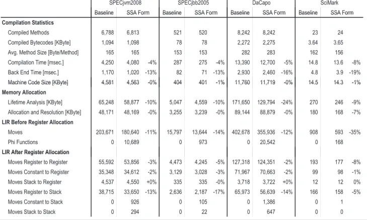
Figure 9. Comparison of compilation statistics.
The same steps are performed for the control flow edge fromB3 toB4. The location of intervali10iss1at the end ofB2andeax at the beginning ofB4, so a move froms1toeaxis added. The phi function requires a resolving move from intervali12toi14, i.e., from the locations2toecx. Because the operands of the two moves are not overlapping, they can be emitted in any order, and resolving the mapping is trivial in this case.
Both the source and target operand of a move can be a stack slot. Because one interval is assigned only one stack slot even when it is split and spilled multiple times, moves between two different stack slots can only occur with our added handling for phi func-tions. Stack-to-stack moves are not supported by most architectures and must be emulated with either a load and a store to a register currently not in use, or a push and a pop of a memory location if no register is free. Our implementation for the Intel x86 architec-ture does not reserve a scratch register that is always available for such moves. However, the register allocator has exact knowledge if there is a register that is currently unused, and it is also possible to use a floating point register for an integer value because no com-putations need to be performed. Therefore, a register is available in nearly all cases. Still, a stack-to-stack moves requires two machine instructions, so we try to assign the same stack slot to the source and target of a phi function when the according intervals do not overlap.
7.
Evaluation
We modified the client compiler of Sun Microsystems’ Java HotSpotTMVM, using an early snapshot version of the upcoming JDK 7 available from the OpenJDK project [27]. All benchmarks are executed on a system with two Intel Xeon X5140 2.33 GHz processors, 4 cores, and 32 GByte main memory, running Ubuntu
Linux with kernel version 2.6.28. The results are obtained using 32-bit VMs.
We compare our modified linear scan algorithm that oper-ates on SSA form with the unmodified baseline version of the JDK. We evaluate using the following groups of benchmarks: (1) SPECjvm2008 [26] excluding the startup benchmarks (because each of these runs in a new VM but we want to accumulate com-pilation counters of one VM run) and the SciMark benchmarks (because we evaluate them separately), (2) SPECjbb2005 [25], (3) the DaCapo benchmarks [2] version 2006-10-MR2, and (4) Sci-Mark 2.0 [23]. SciSci-Mark is available both standalone and as part of SPECjvm2008. It consists of scientific kernels that require only few methods to be compiled. We use the standalone version because the framework infrastructure of SPECjvm2008 would significantly in-crease the number of compiled methods.
7.1 Impact on Compile Time
Measuring the compile time is complicated because compilation is done in parallel with execution and thus subject to random noise. In particular, the Java HotSpotTM VM does not allow the recording and replaying of a certain set of compiled methods. Therefore, a slightly different set of methods is compiled when repeatedly executing the same benchmark. To reduce this noise, we limit the benchmarks to one benchmark thread if possible, disable compilation in a separate thread, and report the average of 20 executions. The standard deviation of the number of compiled methods and the size of compiled bytecodes is less than 0.8% (relative to the reported mean) for all benchmarks. Nevertheless, Figure 9 shows slightly different numbers when comparing the baseline and our modified version of the client compiler.
The first group of rows in Figure 9 shows the basic compilation statistics. SPECjvm2008 and DaCapo are large benchmark suites
42 0 32 0 31 23 93 0 65 0 1. 8 1. 3 37 0 37 0 25 25 72 0 72 0 1. 4 1. 3 11 0 12 0 7 8 41 0 41 0 0. 4 0. 5 40% 60% 80% 100% Resolution Linear Scan Lifetime Analysis LIR Construction 27 0 21 0 19 15 87 0 68 0 1. 2 0. 8 42 0 32 0 31 23 93 0 65 0 1. 8 1. 3 37 0 37 0 25 25 72 0 72 0 1. 4 1. 3 11 0 12 0 7 8 41 0 41 0 0. 4 0. 5 0% 20% 40% 60% 80% 100% B S B S B S B S Resolution Linear Scan Lifetime Analysis LIR Construction jvm2008 jbb2005 DaCapo SciMark 27 0 21 0 19 15 87 0 68 0 1. 2 0. 8 42 0 32 0 31 23 93 0 65 0 1. 8 1. 3 37 0 37 0 25 25 72 0 72 0 1. 4 1. 3 11 0 12 0 7 8 41 0 41 0 0. 4 0. 5 0% 20% 40% 60% 80% 100% B S B S B S B S Resolution Linear Scan Lifetime Analysis LIR Construction jvm2008 jbb2005 DaCapo SciMark
Figure 10. Compilation time of baseline (B) and SSA form (S) version of linear scan.
where several thousand methods are compiled, SPECjbb2005 is of medium size, and SciMark is small and requires only few methods to be compiled. The average method size of the DaCapo bench-marks is significantly larger than for the other benchbench-marks. The lower compilation speed indicates that the overall compilation time does not scale linearly with the method size, which is reasonable because some optimizations of the client compiler do not run in linear time. The average method size of SciMark is comparable to SPECjvm2008 and SPECjvm2005, however SciMark consists only of methods with several nested loops. This leads to a higher den-sity of phi functions and thus a different behavior of the compiler. SPECjvm2008 and SPECjbb2005 show roughly the same behavior for all aspects of the compiler that we measured.
Our new register allocator decreases the overall compilation time by 4% to 8%. The percentage for SciMark is larger compared to the other benchmarks because the compiler spends less time optimizing the HIR in the front end. The time spent in the back end optimized by our changes (LIR construction, lifetime analysis, linear scan register allocation, and resolution) is reduced by 13% to 19%.
Figure 10 shows the detailed numbers for these four compiler phases. For each benchmark, the first bar (B) shows the baseline and the second bar (S) our modified SSA form version of linear scan. The sizes of the bars are normalized to the baseline of the according benchmark. The numbers shown inside the bars are the total time in milliseconds spent in this phase, so they sum up to the back end time row of Figure 9. LIR construction is 19% to 27% faster because SSA form deconstruction is no longer performed. The lifetime analysis is 25% to 31% faster because the algorithm described in Section 4 needs no global data flow analysis. The time necessary for the linear scan algorithm is mostly unchanged be-cause our changes are minor. Only SciMark shows a 13% speedup due to a high density of phi functions, whose intervals are simpler now. The elimination of interval intersection checks described in Section 5 does not gain a measurable speedup. The resolution phase is 1% to 10% slower because it now includes SSA form deconstruc-tion. However, the additional time for the resolution phase is much smaller than the time saved during LIR construction, because SSA form deconstruction is only a small addition to the resolution algo-rithm while it was a complex algoalgo-rithm during LIR construction.
The reduced compilation time is also accompanied by a re-duced memory consumption. Because no intermediate data struc-tures for the data flow analysis are necessary, and the lifetime inter-vals for phi functions have fewer lifetime holes, the total memory
allocated during lifetime analysis is reduced by 9% to 24%. The memory allocated during the linear scan algorithm and resolution is mostly unchanged, only SciMark requires 7% less memory for these phases.
The bottom half of Figure 9 shows how our changes affect the number of move operations. Before register allocation, the number of moves is 11% to 35% lower because phi functions are not yet resolved with moves. But even the sum of the number of moves and phi functions is lower than the original number of moves because one phi function needs to be resolved to at least two moves.
After register allocation, when all phi functions are already resolved, the number of moves is still lower, especially the moves from a register to the stack. This benefit is partially alleviated by two new categories of moves introduced by our changes: (1) moves from a constant to the stack, and (2) moves between two stack slots. These moves are introduced because the lifetime interval of a phi function can have a stack slot assigned at the point of definition. If a block has more phi functions than the processor has physical registers, this assignment is inevitable because the intervals for the phi functions all start at the same position. In the old implementation, the phi functions were already resolved by a series of moves, and spill decisions could be made after each move. This resulted in cases where, for example, a constant was loaded to a register and then the register was immediately spilled to a stack slot. Now, the constant is stored directly into the stack slot, leading to fewer moves in total. Because of the lower number of moves, the overall machine code size is also reduced, however this change is rather insignificant (1% or less).
7.2 Impact on Run Time
The impact of our changes on the run time of the benchmarks are low. Because the main allocation algorithm of linear scan is unchanged, mostly the same allocation and spilling decisions are made with and without SSA form. The speedups are generally be-low the random noise and therefore not statistically significant. The only exception is the FFT benchmark of SciMark with a speedup of 1%, which is statistically significant because of the low variance of SciMark results. It is caused by fewer moves in the heavily ex-ecuted innermost computation loop of the benchmark. There is no slowdown for any benchmark.
7.3 Impact on Compiler Code Size
Our modifications simplify the code of the client compiler and reduce its code size. We measure the impact on the lines of C++ code, not counting empty lines, comments, assertions, verification code, debug outputs, and any other code excluded from product builds. The old code for SSA form deconstruction before register allocation is completely unnecessary, eliminating about 180 lines. Only about 20 lines are added to perform SSA form deconstruction during resolution. The old code for initializing the data structures and performing the global data flow analysis required about 150 lines and is now unnecessary. Our new algorithm for building lifetime intervals, which is an extension of code that was already present, added about 100 lines. Additionally, a number of smaller changes both removed and added some lines. In total, the new code is about 200 lines shorter than the old code.
8.
Related Work
Poletto et al. introduced the linear scan algorithm [22]. Their vari-ant does not use lifetime holes and is not able to split intervals, i.e., an interval has either one register assigned or is spilled for its entire lifetime. This restricts the allocator but allows for a fast allocation because it does not require a resolution phase. They already men-tioned that building the lifetime intervals consumes a considerable
amount of the allocation time, and experimented with conserva-tive heuristics for fast building of intervals. However, note that it is not possible to do without a lifetime analysis. The second chance binpacking algorithm of Traub et al. added lifetime holes and in-terval splitting [28]. This makes the linear scan algorithm suitable for architectures with a low number of registers and few or even no callee-saved registers.
In previous work, we presented additional optimizations that improve the quality of linear scan register allocation without im-pacting compile time overly much [30]. We use register hints as a lightweight alternative to coalescing of intervals, move spill stores and loads out of loops, and eliminate redundant spill stores. The implementation for the Java HotSpotTM client compiler is part of the product version since Java 6 and the baseline for this imple-mentation.
Sarkar et al. claim that their extended linear scan algorithm produces better code than graph coloring algorithms [24]. They show that the abstraction of graph coloring introduces unnecessary constraints that can be avoided by a linear scan algorithm with aggressive splitting of lifetime intervals. However, they only cover spill free register allocation as well as register allocation with total spills where entire lifetime intervals are spilled. This is a severe restriction especially for register constrained architectures. None of the previously mentioned versions of linear scan operates on SSA form.
M¨ossenb¨ock et al. provide an early approach to perform lin-ear scan register allocation directly on SSA form [19]. However, they still deconstruct SSA form before register allocation during the construction of the lifetime intervals: They insert move instruc-tions into predecessor blocks for phi funcinstruc-tions, leading to intervals that start in the predecessor blocks and extending into the succes-sor. They only keep the phi functions in the successor block as a placeholder to start a new interval. They use data flow analysis to construct the lifetime intervals, pre-order the moves and phi tions instead of using the parallel copy semantics of the phi func-tions, and use no structural properties guaranteed by SSA form.
The original graph coloring register allocators (see for exam-ple [5, 8]) are not based on SSA form. Only recently, the properties guaranteed by SSA form were found to be beneficial [6, 12]. The same properties that we use to simplify linear scan register alloca-tion, namely that the definition of every value dominates all uses and that it is enough to check interference at the definition points of values [7], simplify the construction of the interference graph and allow spilling decisions to be decoupled from the actual col-oring phase. Hack et al. present an implementation for the libFirm library [14]. Copy coalescing of phi functions and their arguments is performed via graph recoloring [13].
Pereira et al. use the even more specialized static single infor-mation (SSI) form for their register allocation based on puzzle solv-ing [20]. SSI form requires not only phi functions for all variables at every join point, but also pi functions at every point where con-trol flow splits. They claim to be faster and better than linear scan register allocation, however their comparison is performed with a linear scan variant not based on SSA form such as our implemen-tation.
Boissinot et al. present a fast algorithm for liveness check-ing of SSA form programs, uscheck-ing the structural properties guar-anteed by SSA form [4]. Their algorithm performs only few pre-computations, but still allows fast answers to the question whether a certain value is live at a certain point in a method. It is not designed to allow fast answers for all points in the program, therefore it is not suitable for building lifetime intervals. Our algorithm to build lifetime intervals requires more time than their pre-computation, but then the intervals contain information about the lifetime of all values for the entire method.
Boissinot et al. present an algorithm for SSA form deconstruc-tion that is provably correct [3]. The complicadeconstruc-tions they describe where previous algorithms failed only arise when critical edges of the control flow graph cannot be split. However, this is always pos-sible when compiling from Java bytecodes, so this is not a concern for our simple integration of SSA form deconstruction into the res-olution phase of the linear scan algorithm.
Pereira et al. provide an algorithm for SSA form deconstruction after register allocation [21]. It requires the input program to be in conventional SSA (CSSA) form. Additionally to the normal SSA form properties, CSSA form requires that all variables of a phi function do not interfere. For example, the lifetime intervals of a phi function’s input parameters must neither overlap the lifetime interval of the phi function, nor themselves. CSSA form can be obtained from SSA form by splitting life ranges that violate this property, leading to a higher number of variables. However, it is then always safe to assign the same stack slot to a phi function and all its input parameters when spilling is necessary. This avoids moves between two different stack slots, which sometimes occur with our algorithm.
9.
Conclusions
Linear scan is a fast algorithm for register allocation especially used by just-in-time compilers. This paper explored how the al-gorithm benefits from an intermediate representation in SSA form. The dominance property guaranteed by SSA form allows for a sim-ple construction of lifetime intervals and eliminates checks for in-terval intersection during allocation. Additionally, SSA form de-construction can be easily integrated into the resolution phase of the register allocator. Our implementation for the Java HotSpotTM client compiler shows that the resulting algorithm is both simpler and faster.
Acknowledgments
Parts of this effort have been sponsored by the California MICRO Program and industrial sponsor Sun Microsystems under Project No. 07-127, as well as by the National Science Foundation (NSF) under grants CNS-0615443 and CNS-0627747. Further support has come from generous unrestricted gifts from Sun Microsystems, Google, and Mozilla, for which the authors are immensely grateful. The U.S. Government is authorized to reproduce and distribute reprints for Governmental purposes notwithstanding any copyright annotation thereon. Any opinions, findings, and conclusions or rec-ommendations expressed here are those of the authors and should not be interpreted as necessarily representing the official views, policies, or endorsements, either expressed or implied, of the NSF, any other agency of the U.S. Government, or any of the companies mentioned above.
References
[1] B. Alpern, C. R. Attanasio, J. J. Barton, M. G. Burke, P.Cheng, J.-D. Choi, A. Cocchi, S. J. Fink, D. Grove, M. Hind, S. F. Hummel, D. Lieber, V. Litvinov, M. F. Mergen, T. Ngo, J. R. Russell, V. Sarkar, M. J. Serrano, J. C. Shepherd, S. E. Smith, V. C. Sreedhar, H. Srinivasan, and J. Whaley. The Jalape˜no virtual machine. IBM
Systems Journal, 39(1):211–238, 2000.
[2] S. M. Blackburn, R. Garner, C. Hoffman, A. M. Khan, K. S. McKinley, R. Bentzur, A. Diwan, D. Feinberg, D. Frampton, S. Z. Guyer, M. Hirzel, A. Hosking, M. Jump, H. Lee, J. E. B. Moss, A. Phansalkar, D. Stefanovi´c, T. VanDrunen, D. von Dincklage, and B. Wiedermann. The DaCapo benchmarks: Java benchmarking development and analysis. In Proceedings of the ACM SIGPLAN
Conference on Object-Oriented Programming Systems, Languages, and Applications, pages 169–190. ACM Press, 2006.
[3] B. Boissinot, A. Darte, F. Rastello, B. D. de Dinechin, and C. Guillon. Revisiting out-of-SSA translation for correctness, code quality and efficiency. In Proceedings of the International Symposium on Code
Generation and Optimization, pages 114–125. IEEE Computer
Society, 2009.
[4] B. Boissinot, S. Hack, D. Grund, B. Dupont de Dinechin, and F. Rastello. Fast liveness checking for SSA-form programs. In
Proceedings of the International Symposium on Code Generation and Optimization, pages 35–44. ACM Press, 2008.
[5] P. Briggs, K. D. Cooper, and L. Torczon. Improvements to graph coloring register allocation. ACM Transactions on Programming
Languages and Systems, 16(3):428–455, 1994.
[6] P. Brisk, F. Dabiri, R. Jafari, and M. Sarrafzadeh. Optimal register sharing for high-level synthesis of SSA form programs. IEEE
Transactions on Computer-Aided Design of Integrated Circuits and Systems, 25(5):772–779, 2006.
[7] Z. Budimlic, K. D. Cooper, T. J. Harvey, K. Kennedy, T. S. Oberg, and S. W. Reeves. Fast copy coalescing and live-range identification. In Proceedings of the ACM SIGPLAN Conference on Programming
Language Design and Implementation, pages 25–32. ACM Press,
2002.
[8] G. J. Chaitin, M. A. Auslander, A. K. Chandra, J. Cocke, M. E. Hopkins, and P. W. Markstein. Register allocation via coloring.
Computer Languages, 6:47–57, 1981.
[9] R. Cytron, J. Ferrante, B. K. Rosen, M. N. Wegman, and F. K. Zadeck. Efficiently computing static single assignment form and the control dependence graph. ACM Transactions on Programming Languages
and Systems, 13(4):451–490, 1991.
[10] S. J. Fink and F. Qian. Design, implementation and evaluation of adaptive recompilation with on-stack replacement. In Proceedings of
the International Symposium on Code Generation and Optimization,
pages 241–252. IEEE Computer Society, 2003.
[11] R. Griesemer and S. Mitrovic. A compiler for the Java HotSpotTM virtual machine. In The School of Niklaus Wirth: The Art of Simplicity, pages 133–152. dpunkt.verlag, 2000.
[12] S. Hack and G. Goos. Optimal register allocation for SSA-form programs in polynomial time. Information Processing Letters, 98(4):150–155, 2006.
[13] S. Hack and G. Goos. Copy coalescing by graph recoloring. In
Proceedings of the ACM SIGPLAN Conference on Programming Language Design and Implementation, pages 227–237. ACM Press,
2008.
[14] S. Hack, D. Grund, and G. Goos. Register allocation for programs in SSA-form. In Proceedings of the International Conference
on Compiler Construction, pages 247–262. LNCS 3923, Springer
Verlag, 2006.
[15] U. H ¨olzle and D. Ungar. Optimizing dynamically-dispatched calls with run-time type feedback. In Proceedings of the ACM SIGPLAN
Conference on Programming Language Design and Implementation,
pages 326–336. ACM Press, 1994.
[16] T. Kotzmann, C. Wimmer, H. M¨ossenb¨ock, T. Rodriguez, K. Russell, and D. Cox. Design of the Java HotSpotTM client compiler for Java 6. ACM Transactions on Architecture and Code Optimization, 5(1):Article 7, 2008.
[17] C. Lattner and V. Adve. LLVM: A compilation framework for lifelong program analysis & transformation. In Proceedings of the
International Symposium on Code Generation and Optimization,
pages 75–88. IEEE Computer Society, 2004.
[18] T. Lindholm and F. Yellin. The JavaTMVirtual Machine Specification. Addison-Wesley, 2nd edition, 1999.
[19] H. M¨ossenb¨ock and M. Pfeiffer. Linear scan register allocation in the context of SSA form and register constraints. In Proceedings of the
International Conference on Compiler Construction, pages 229–246.
LNCS 2304, Springer-Verlag, 2002.
[20] F. M. Q. Pereira and J. Palsberg. Register allocation by puzzle solving. In Proceedings of the ACM SIGPLAN Conference on Programming
Language Design and Implementation, pages 216–226. ACM Press,
2008.
[21] F. M. Q. Pereira and J. Palsberg. SSA elimination after register allocation. In Proceedings of the International Conference on
Compiler Construction, pages 158–173. LNCS 5501, Springer
Verlag, 2009.
[22] M. Poletto and V. Sarkar. Linear scan register allocation. ACM
Transactions on Programming Languages and Systems, 21(5):895–
913, 1999.
[23] R. Pozo and B. Miller. SciMark 2.0, 1999. http://math.nist.gov/ scimark2/.
[24] V. Sarkar and R. Barik. Extended linear scan: An alternate foundation for global register allocation. In Proceedings of the International
Conference on Compiler Construction, pages 141–155. LNCS 4420,
Springer Verlag, 2007.
[25] Standard Performance Evaluation Corporation. SPECjbb2005, 2005. http://www.spec.org/jbb2005/.
[26] Standard Performance Evaluation Corporation. SPECjvm2008, 2008. http://www.spec.org/jvm2008/.
[27] Sun Microsystems, Inc. OpenJDK, 2009. http://openjdk.java.net/. [28] O. Traub, G. Holloway, and M. D. Smith. Quality and speed in
linear-scan register allocation. In Proceedings of the ACM SIGPLAN
Conference on Programming Language Design and Implementation,
pages 142–151. ACM Press, 1998.
[29] C. Wimmer. Linear scan register allocation for the Java HotSpotTM client compiler. Master’s thesis, Johannes Kepler University Linz, 2004.
[30] C. Wimmer and H. M¨ossenb¨ock. Optimized interval splitting in a linear scan register allocator. In Proceedings of the ACM/USENIX
International Conference on Virtual Execution Environments, pages