date of current version December 22, 2015.
Digital Object Identifier 10.1109/ACCESS.2015.2503266
Fully Parallel Turbo Equalization for
Wireless Communications
HOANG ANH NGO, ROBERT G. MAUNDER, AND LAJOS HANZO Department of Electronics and Computer Science, University of Southampton, Southampton SO17 1BJ, U.K.
Corresponding author: L. Hanzo ([email protected])
The financial support of the EPSRC, Swindon UK under the grants EP/J015520/1 and EP/L010550/1, as well as that of the TSB, Swindon UK under the auspices of grant TS/L009390/1 is gratefully acknowledged.
ABSTRACT Iterative turbo equalization is capable of achieving impressive performance gains over the conventional non-iterative equalization having the same complexity, when communicating over channels that suffer from intersymbol interference (ISI). The state-of-the-art turbo equalizers employ the logarithmic Bahl–Cocke–Jelinek–Raviv (Log-BCJR) algorithm. However, due to the specific nature of serial data processing, the Log-BCJR algorithm introduces significant processing delays at the receiver. Therefore, in low-latency applications having a high throughput, the turbo equalizer might be deemed less attractive than its conventional counterparts. In order to circumvent this problem, in this paper, we conceived a novel fully parallel turbo equalization algorithm, which is capable of significantly reducing the data processing delay and, hence, improving both the processing latency and the attainable throughput at the receiver. The fully parallel equalizer is then combined with the fully parallel turbo decoder for improving the system performance achieved in terms of the bit error ratio. Furthermore, we propose a novel odd–even interleaver design for employment between the fully parallel equalizer and the fully parallel turbo decoder in order to reduce complexity by 50% in fully parallel turbo equalization arrangements, while retaining a comparable performance. Finally, we compare the computational complexity, latency, throughput, hardware resource requirements, and the bit error ratio of the proposed fully parallel scheme to those of a Log-BCJR-based turbo equalizer benchmarker.
INDEX TERMS Fully-parallel turbo equalization, iterative equalization and decoding.
NOMENCLATURE
ACRONYMS
ARP Almost regular Permutation
AWGN Additive White Gaussian Noise
BER Bit Error Ratio
BPSK Binary Phase Shift Keying
Log-BCJR Logarithmic Bahl-Cocke-Jelinek-Raviv
FPTD Fully-Parallel Turbo Decoder
FPTDS Fully-Parallel Turbo Detection Scheme
FPE Fully-Parallel Equalizer
LLR Logarithmic Likelihood Ratio
LTE Long Term Evolution
NSW Non-Slide Windows
QPP Quadratic Polynomial Permutation
RAM Random Access Memory
WCDMA Wideband Code Division Multiple Access
LIST OF SYMBOLS
b The multiplexed bit vector at the transmitter
b1 The message bit vector at the transmitter b2 The parity bit vector at the transmitter
b3 The systematic bit vector at the transmitter ¯
ba The a priori multiplexed LLR vector at the receiver ¯
be The extrinsic multiplexed LLR vector at the receiver ¯
ba1 The a priori message LLR vector at the turbo decoder
¯
be1 The extrinsic message LLR vector at the turbo decoder
¯
ba2 The a priori parity LLR vector at the turbo decoder
¯
be2 The extrinsic parity LLR vector at the turbo decoder
¯ ba
3 The a priori systematic LLR vector at
the turbo decoder
¯
be3 The extrinsic systematic LLR vector at the turbo decoder
¯
bp3 Thea posteriorisystematic LLR vector at the turbo decoder
c The interleaved bit vector at the transmitter
cc The transmitted symbol vector at the transmitter
¯
ca Thea prioriLLR vector of the equalizer
¯
cc The received symbol vector of the equalizer
¯
ce The extrinsic LLR vector of the equalizer
n The additive white Gaussian noise
2652
2169-35362015 IEEE. Translations and content mining are permitted for academic research only.
¯
αa Thea prioriforward state metric of
the turbo decoder
¯
αe The extrinsic forward state metric of
the turbo decoder
¯
βa Thea prioribackward state metric of the turbo decoder
¯
βe The extrinsic backward state metric of the turbo decoder
¯
αE,a Thea prioriforward state metric of the equalizer ¯
αE,e The extrinsic forward state metric of the equalizer ¯
βE,a Thea prioribackward state metric of the equalizer
¯
βE,e
The extrinsic backward state metric of the equalizer
C The computational complexity
D The time period duration
I The number of decoding iterations
II The number of equalizer-to-turbo-decoder iterations IO The number of turbo-decoder iterations
L The number of states in the equalizer trellis M The number of states in the turbo code trellis
N Frame length
Sk Thekthstate of the trellis
T The number of time periods per decoding iteration
X The computational resource requirement
Y The register resource requirement
Z The RAM resource requirement
h The fading coefficient
k Bit/symbol/state index
l Tap index
l Lower encoder/decoder
u Upper encoder/decoder
I. INTRODUCTION
Berrou and his team [1] proposed the first turbo equalisa-tion scheme, where the equalizer and the channel decoder exchange their soft-decision based information by perform-ing iterative detection in order to gradually eliminate the channel-induced Inter-Symbol Interference (ISI). Inspired by this contribution, this problem was further investi-gated by a large number of researches [2], [3]. As shown in [4] and [5], the turbo equalizers offer a substantially improved performance over the family of non-iterative linear equalizers [6], [7]. The closely-related family of turbo codes [8], [9] has been adopted for providing error cor-rection in a number of advanced communication systems, such as the 3rd-Generation Wideband Code Division Multiple
Access (3G WCDMA) [10], [11] and the 4th-Generation
Long Term Evolution (4G LTE) systems [12]. A turbo detec-tion scheme [13], [14] may comprise a serial concatenadetec-tion of an equalizer with a turbo decoder, which comprises a paral-lel concatenation of two component convolutional decoders. By iteratively exchanging soft information in the form of Logarithmic Likelihood Ratios (LLRs) [8] between the equal-izer and the pair of constitute convolutional decoders of the turbo code, the resultant turbo detection scheme is capable of
facilitating reliable communications at transmission through-puts that approach the channel capacity [3], [15]. Classic turbo detection schemes typically employ the Logarithmic Bahl-Cocke-Jelinek-Raviv (Log-BCJR) algorithm [16]. This is successively applied to the equalizer and to the two con-volutional decoders, until an error-free decoded frame is obtained or until the maximum number of decoding iterations is reached. However, the Log-BCJR algorithm has an inher-ently serial processing nature, owing to the data dependencies within its forward and backward recursions as detailed in [3]. This limits both the achievable processing throughput and the latency of conventional turbo detection schemes, which imposes a bottleneck both on the transmission throughput and on the end-to-end latency in real-time communication systems.
A number of techniques have been proposed for increasing the grade of parallelism and hence for improving both the pro-cessing throughput and latency of Log-BCJR turbo decoders although these techniques have only found limited appli-cation to turbo equalizers. These solutions include shuffled iterative decoding [17], sub-block parallelism [18], [19], the Radix-4 transform [20] and the Non-Sliding Window (NSW) technique [20]. These techniques allow both recursions of both convolutional decoders to be performed simultaneously, as well as allowing the recursions to consider several turbo-encoded bits per time period. However, in each case, the data dependencies of the forward and backward recursions require the turbo encoded bits of each convolutional decoder to be processed serially, spread over numerous consecutive time periods. As a result, each turbo decoding iteration requires hundreds or even thousands of processing time periods, hence limiting the attainable processing throughput of the state-of-art turbo decoder [20] to 2.15 Gbit/s, which is far below the 10 Gbit/s target of the emerging 5G systems [21].
Against this background, we previously proposed the Fully-Parallel Turbo Decoder (FPTD) algorithm [22], where all turbo-encoded bits in the frame may be decoded in par-allel, allowing each turbo decoder iteration to be completed using just one or two time periods. This offers a more than six-fold processing throughput and latency improvement over the state-of-the-art Log-BCJR turbo decoder, when employed for the LTE turbo code [22]. As a result, the FPTD facilitates both processing throughputs exceeding 10 Gbit/s and ultra-low processing latencies, hence satisfying the challenging requirements of 5G for the first time. The milestones of the development of the iterative turbo decoding and turbo equalization are shown in Table 1.
Against this background, in this paper we propose a novel Fully-Parallel Turbo Detection Scheme (FPTDS) for high-throughput and low-latency applications. Our novel contri-butions are detailed as follows:
1) We propose a novel Fully-Parallel Equalizer (FPE), as well as FPTDS, where the FPE is operated in parallel with the FPTD conceived in [22] and [26].
2) We propose a novel odd-even interleaver for the pro-posed FPTDS in order to reduce the complexity of the
TABLE 1. Development of turbo decoding and turbo equalization.
system by 50%, while maintaining a comparable Bit Error Ratio (BER).
3) We quantified the computational complexity, latency, throughput, hardware resource requirements as well as BER of the proposed FPTDS and compared them to those of the conventional Log-BCJR turbo detection benchmarkers.
The outline of the paper is as follows. Section II describes our novel FPTDS, where the novel FPE and the FPTD are operated in parallel. Our novel odd-even interleaver Con-ceived for reducing the computational complexity of the FPTDS is proposed in Section III. Section IV investigates the computational complexity, throughput, hardware resource requirements of the FPTDS and compare them to those of the Log-BCJR benchmarkers. The BER performance of the proposed FPTDS is quantified and compared to the bench-markers in Section V. Finally, our concluding remarks are offered in Section VI.
II. SYSTEM ARCHITECTURE
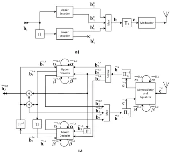
The architecture of the proposed FPTDS is shown in Fig.1. In the turbo encoder [8] of the transmitter, a message bit vector bu1 = [bu1,k]Nk=1 comprising N number of bits is encoded by the upper convolutional encoder, generating the parity bit vectorbu
2=[bu2,k]Nk=1and the systematic bit vector bu3=[bu3,k]Nk=1 =bu1. Meanwhile, the message bit vectorbu1
is interleaved by the block5in order to obtain the interleaved message bit vector bl1 = [b1l,k]Nk=1 and then it is encoded by the lower convolutional encoder to produce the parity bit vector bl2 = [b2l,k]Nk=1. Following this, the systematic bit
FIGURE 1. The iterative equalization and decoding system. (a) Transmitter. (b) Receiver.
vectorbu3and the parity bit vectorsbu2andbl2are multiplexed in order to form the bit vectorb = [bk]3Nk=1comprising 3N
bits, which is then interleaved by the block5E of Fig. 1 into the bit vectorc = [ck]3Nk=1. Finally, the bit vector cis
modulated, resulting in the symbol vectorcc =[cck]3Nk=1. For simplicity, Binary Phase Shift Keying (BPSK) modulation is assumed, according tocck =2ck−1.
The symbol vector cc is assumed to travel through a wireless channel which is contaminated by ISI caused by
multipath fading having ` taps and then by the Additive Gaussian White Noise (AWGN) n = [nk]3Nk=1 having a
noise variance ofσ2. The fading coefficients [hl]`l=0obey the
Rayleigh distribution and are normalized to a unity power. The received signal may be modelled as:
¯ cck= ` X l=0 hlcck−l+nk, k=1,2, . . . ,3N. (1)
In the following sections, we will describe the conventional Log-BCJR turbo detection scheme and the novel FPTDS. In each section, we will detail the equalizer, the turbo decoder and the iterative turbo equalization and decoding operations exchanging soft-information between them.
A. CONVENTIONAL LOG-BCJR TURBO DETECTION
The conventional equalization and decoding may rely on II equalizer-to-turbo-decoder and IO turbo-decoder itera-tions. The equalizer-to-turbo-decoder iterations are carried out between the equalizer and the turbo decoder, while the turbo-decoder iterations are performed between the two component decoders of the turbo decoder. The equalizer-to-turbo-decoder iterations between the equalizer and the turbo decoder are continued, until no more errors are detected or until reaching the maximum affordable number of equalizer-to-turbo-decoder iterations. The presence of errors may be detected using classic error detection codes, such as Cyclic Redundancy Check (CRC) codes.
1) LOG-BCJR EQUALIZER
The received signal vector of 3N symbolc¯cis first equalized by the equalizer, where the Log-BCJR equalization algo-rithm [4] is employed. As seen in Fig. 1, the inputs of the turbo equaliser comprise the symbol vectorc¯c =[c¯ck]3Nk=1received from the channel and thea prioriLLR vectorsc¯a =[¯ca
k] 3N k=1
gleaned from the turbo decoders.
In response, the turbo equaliser forwards the extrinsic LLR vector c¯e = [¯cek]3Nk=1 to the turbo decoder. Before being forwarded to the turbo decoder, the extrinsic LLR vector¯ce
is deinterleaved by the block5−E1of Fig. 1 into the vector of turbo-encoded LLRsb¯a = [b¯a
k] 3N
k=1and then demultiplexed
into three a priori LLR vectors b¯u,a2 , b¯l,a2 and b¯u,a3 , where the latter is deinterleaved by the block 5−1 of Fig. 1 to obtainb¯l,a3.
In each iteration, the equalizer will sequentially compute the 3N extrinsic LLRs of c¯e based on (2)-(6). More
specif-ically, the equalizer uses (2) to combine the 3N LLRs c¯ck
and the 3N LLRs c¯ak gleaned from the channel and from the FPTD, respectively, in order to to produce an a priori transition metric γ¯E
k(Sk−1,Sk) for each transition in the
L =log2(`−1)-state trellis [4], namely for each pair of states Sk−1andSk, for which it is possible for the equalizer to
transi-tion between, as indicated using the notatransi-tionb(Sk−1,Sk)=1.
Then the 3N extrinsic forward state metric vectors
¯ αE = ¯ αE k = [α¯Ek(Sk)]MSk−=10 3N
k=1 and the 3N extrinsic
backward state metric vectors β¯E = β¯Ek−1 =
[β¯kE−1(Sk−1)]MS−1
k−1=0 3N
k=1are computed by (3) and (4),
respec-tively. As shown in (3), thekthforward metricα¯E
k(Sk) depends
on the (k −1)th forward metric α¯E
k−1(Sk). Therefore, the
3Nthforward metricα¯E
3N(Sk) depends on the (3N−1)th
previ-ous forward metrics. Consequently, the forward recursion is spread over 3N time periods, resulting in a slow processing. This is similar in the backward recursion.
¯ δE(S k−1,Sk)= b0(Sk−1,Sk)· ¯cak (2) + ¯c c k− ` X l=0 (2bl(Sk−1,Sk)−1)·hl 2 /(2σ2) , ¯ αE k(Sk)= max* {Sk−1|c(Sk−1,Sk)=1} γE k(Sk−1,Sk)+ ¯αEk−1(Sk−1) , (3) ¯ βE k−1(Sk−1)= max* {Sk|c(Sk−1,Sk)=1} γE k(Sk−1,Sk)+ ¯βkE(Sk) , (4) ¯ δE(S k−1,Sk)= ¯γkE(Sk−1,Sk)+ ¯αkE−1(Sk−1)+ ¯βkE(Sk), (5) ¯ cek= max* {(Sk−1,Sk)|b1(Sk−1,Sk)=1} [δ¯E(Sk−1,Sk)] − max* {(Sk−1,Sk)|b1(Sk−1,Sk)=0} [δ¯E(Sk−1,Sk)] − ¯cak. (6) Equations (3) and (4) employ the Jacobian logarithm, which is defined for two operands as [8]
max∗(δ1,¯ δ2¯ )=max(δ1,¯ δ2¯ )+ln 1+e−|(δ¯1− ¯δ2)|,
(7) and may be extended to more operands by exploiting its associative property. Alternatively, the exact max∗of (7) may be approximated by [27]
max∗(δ1,¯ δ2¯ )=max(δ1,¯ δ2¯ ) (8)
Thereafter, ana posterioritransition metricsδ¯Ek(Sk−1,Sk)
is produced by (12) for each transition between the stateSk−1
andSkin the trellis. Finally, (13) is employed to generate the
vector of 3N extrinsic LLRs c¯e = [c¯e k]
3N
k=1, which will be
forwarded to the channel decoder. 2) LOG-BCJR TURBO DECODER
Again, the classic turbo decoder includes a pair of convo-lutional component decoders, where both rely on the Log-BCJR decoding algorithm [8], [22]. As illustrated in Fig. 1, the inputs of each component decoder comprise thea priori systematic LLR vectorb¯a3=[b¯3a,k]Nk=1and thea prioriparity LLR vectorb¯a2 = [b¯a2,k]Nk=1 from the equalizer, as well as thea priorimessage LLR vector b¯a1 = [b¯a1,k]Nk=1 from the other component decoder. Meanwhile, the outputs comprise the extrinsic message LLR vectorb¯e1=[b¯e1,k]Nk=1for the other decoder and the encoded extrinsic LLR vectorb¯e2=[b¯e2,k]Nk=1 for the equalizer. For convenience, the superscriptsu andl
are omitted in this section and thereafter, wherever our dis-cussions are equivalent for the upper and lower convolutional decoders.
Similar to the equalizer, the decoding operations of the component decoders employ the Log-BCJR algorithm based on (9)-(14). More specifically, each component uses (9) to combine the a priori LLRs b¯a1,k,b¯a2,k and b¯a3,k to produce an a prioritransition metric γk¯ (Sk−1,Sk) for each pair of
transition statesSk1andSk, for which it is possible for the
convolutional encoder to traverse between, as indicated using the notationc(Sk1,Sk)=1. Here,bj(Sk1,Sk) is the value that
is implied for the bitbj,k by the transition between the state
Sk1 andSk, according to the state transition diagram [22].
These vectors of transition metrics are then combined accord-ing to (10)-(11), in order to produce the vector ofN extrinsic forward state metric vectorsα¯ = α¯e
k = [α¯ke(Sk)]MSk−=10
N k=1,
and the vector ofN extrinsic backward state metric vectors
¯
β=β¯ek−1=[β¯ke−1(Sk−1)]MS−1
k−1=0 N
k=1, respectively. Like the
Log-BCJR equalizer, the forward and backward recursions in the Log-BCJR turbo decoder are also spread overNperiods, hence resulting in a slow serial processing.
¯ γk(Sk−1,Sk)= 3 X j=1 [bj(Sk−1,Sk)· ¯baj,k], (9) ¯ αk(Sk)= max* {Sk−1|b1(Sk−1,Sk)=1} h ¯ γk(Sk−1,Sk)+ ¯αk−1(Sk−1) i , (10) ¯ βk−1(Sk−1)= max* {Sk|b1(Sk−1,Sk)=1} h ¯ γk(Sk−1,Sk)+ ¯βk(Sk) i , (11) ¯ δ(Sk−1,Sk)= ¯γk(Sk−1,Sk)+ ¯αk−1(Sk−1)+ ¯βk(Sk), (12) ¯ be1,k= max* {(Sk−1,Sk)|b1(Sk−1,Sk)=1} [δ¯(Sk−1,Sk)] − ¯ba1,k − max* {(Sk−1,Sk)|b1(Sk−1,Sk)=0} [δ¯(Sk−1,Sk)] − ¯ba3,k, (13) ¯ be2,k= max* {(Sk−1,Sk)|b2(Sk−1,Sk)=1} [δ¯(Sk−1,Sk)] − max* {(Sk−1,Sk)|b2(Sk−1,Sk)=0} [δ¯(Sk−1,Sk)] − ¯ba2,k. (14) Thereafter, an a posteriori transition metric δ(Sk−1,Sk)
is computed by (12) for each transition between the states Sk−1 and Sk in the trellis, which is then substituted
into (13) and (14) for generating the uncoded and encoded extrinsic LLR vectorb¯e1,k =b¯e1,kNk=1andb¯e2,k =b¯e2,kNk=1, respectively. Again, these equations rely on the Jacobian logarithm of (7). Following the final turbo-decoder iteration between the two component decoders, an a posterioriLLR pertaining to the kth message bit bu1,k may be obtained as
FIGURE 2. 2D EXIT charts of the FPTD at differentEb/N0values. A LTE
M=8-state turbo code [12] having a coding rate of 1/3 is employed along with BPSK modulation for communication over a Rayleigh fading channel. (a) Block connection of the FPTDS. (b) Block diagram of the FPE. (c) Block diagram of the FPTD.
¯
bu,p3,k = ¯bu,e1,k+ ¯bu,a1,k + ¯bu,a3,k. A hard decision for the message bit bu3,k may then be obtained as the result of the binary testb¯u,p1,k >0.
The extrinsic message LLR vectorsb¯u,e1 andb¯l,e1 are iter-atively exchanged between the upper and lower component decoders forIO iterations. Following this,b¯a,e1 andb¯a,e1 are summed to provideb¯u,e3 . Thenb¯u,e3 ,b¯u,e2 andb¯l,e2 are multi-plexed to obtainb¯e and interleaved to obtainc¯a.
B. FULLY-PARALLEL TURBO DETECTION
In contrast to the conventional turbo detection scheme dis-cussed in Section II-A, all of the symbols in the received symbol vectorc¯cmay be simultaneously equalized by a FPE
and all of the corresponding LLRs may be simultaneously decoded by a FPTD [22] in the FPTDS of Fig. 2, eliminating the requirement for equalizer-to-decoder and turbo-decoder iterations in the system. Instead, in each iteration of the proposed FPTDS, the extrinsic LLR vector is passed from the FPE to the FPTD through the deinterleaver5−E1and the demultiplexer of Fig. 1, while that of the FPTD is forwarded to the FPE through the multiplexer and the interleaver5E of Fig. 1 and Fig. 2a.
1) FPE
The FPE comprises 3N algorithmic decoding blocks, as
detailed in Fig. 2b. Observe in Fig. 2b that the inputs of the FPE comprise the vector of 3N symbolsc¯c = [¯cc
k] 3N k=1
received from the channel, thea priorimessage LLR vector
¯
ca = [c¯a k]
3N
k=1 received from the FPTD during the
previ-ous time period, the a priori forward state metric vectors
¯
αE,a = [α¯E,a k ]
3N−1
k=0 and the a priori backward state metric
vectorsβ¯E,a =[β¯E,ak ]3Nk=1, which are fed back from the FPE during the previous time period. Meanwhile, the output of the FPE includes the extrinsic LLR vector c¯e = [c¯e
k] 3N k=1,
the forward state metric vectorsα¯E,e = [α¯E,e k ]
N
k=0 and the
backward state metric vectorsβ¯E,e =[β¯E,ek ]Nk=0, which will be fed forward to the FPE for use during the next time period. Before being forwarded to the FPTD, the extrinsic LLR vectorc¯eis deinterleaved into the vectorb¯a =[b¯ak]3Nk=1 and then demultiplexed into threea prioriLLR vectorsb¯u,a2 ,
¯
bl,a2 andb¯u,a3 , where the latter is interleaved in the block5to obtain thea prioriLLR vectorb¯l,a3 of Fig. 1.
¯ δE(S k−1,Sk)= ¯αE,ak−1(Sk−1)+ ¯β E,a k (Sk) + b0(Sk−1,Sk)· ¯cak + ¯c c k− ` X l=0 (2bl(Sk−1,Sk)−1)·hl 2 /(2σ2) , (15) ¯ αE,e k (Sk)= max* {Sk−1|c(Sk−1,Sk)=1} [δ¯E(Sk−1,Sk)] − ¯βE,a k (Sk), (16) ¯ βE,e k−1(Sk−1)= max* {Sk|c(Sk−1,Sk)=1} [δ¯E(Sk−1,Sk)] − ¯αE,a k−1(Sk−1), (17) ¯ cek = max* {(Sk−1,Sk)|b1(Sk−1,Sk)=1} [δ¯E(Sk−1,Sk)] − max* {(Sk−1,Sk)|b1(Sk−1,Sk)=0} [δ¯E(Sk−1,Sk)] − ¯cak. (18) In each time period, some or all of the 3N algorithmic blocks of the FPE will compute the outputs based on (15)-(18) at the same time. More specifically, the algorithmic block having the indexkuses (15) to combine the received symbol
¯
cck and thea priori LLR c¯ak gleaned from the channel and the FPTD, respectively, as well as thea prioristate metric vectorsα¯E,a k−1=[α¯ E,a k (Sk)] L−1 Sk=0and ¯ βE,a k =[β¯ E,e k (Sk)] L−1 Sk=0in
order to produce ana posterioristate metricδ¯E(S
k−1,Sk) for
each transition in the state transition diagram [22], namely for each pair of statesSk−1andSkfor which it is possible for
the convolutional encoder to transition between, as indicated using the notationc(Sk−1,Sk) = 1. Note thatbl(Sk−1,Sk)
is the value that is implied for the bitsck−lby the transition
betweenSk−1∈[0,L−1] andSk ∈[0,L−1], whereL=2`.
Thesea posterioritransition metrics are then combined with the aid of (16)-(18), in order to produce the extrinsic forward state metric vectorα¯E,e
k =[α¯ E,e
k (Sk)]MSk−=10, the extrinsic
back-ward state metric vectorβ¯E,ek−1=[β¯ E,e k−1(Sk−1)]
M−1
Sk−1=0and the
extrinsic LLRc¯ek, respectively. Again, (16) and (17) employ the Jacobian logarithm of (7).
In contrast to the classic Log-BCJR equalizer, the for-ward and backfor-ward state metricsα¯E,e
k andβ¯ E,e
k−1 at a given
period only depend on the forward and backward state metrics fed back from the previous time period. Therefore, the data dependencies of the forward and backward recursions are broken, allowing fully-parallel operation. Hence, this speeds up the processing by a factor, of which is up to 3N.
2) FPTD
The FPTD is described and analysed in great detail in [22] and [26]. Briefly, a FPTD includes two convolu-tional component decoders, each of which hasN algorithmic blocks. As illustrated in Fig. 2c, the inputs of each component decoder comprise thea priorisystematic LLR vectorb¯a3 =
[b¯a3,k]Nk=1and thea prioriparity LLR vectorb¯a2 =[b¯a2,k]Nk=1 contributed by the FPE during the previous time period, the a priorimessage LLR vectorb¯a1 = [b¯a1,k]Nk=1gleaned from the other component decoder in the previous time period, the a prioriforward state metric vectorsα¯a =[α¯a
k] N−1 k=0 and the
backward state metric vectorsβ¯a = [β¯ak]Nk=1fed back from the component decoder in the previous time period, where we haveα¯a
k = [α¯ka(Sk)]MSk−=10, ¯
βak−1 = [β¯ka−1(Sk−1)]MSk−−11=0
and M is the number of states in the corresponding state transition diagram [22]. Meanwhile, the outputs comprise the extrinsic message LLR vector b¯e1 = [b¯e1,k]Nk=1 for the other decoder, the forward state metric vectorsα¯e=[α¯e
k] N k=1
and the backward state metric vectorsβ¯e =[β¯ke]Nk=−01which will be fed forward for processing in the next time period,
where α¯e k = [α¯ e k(Sk)] M−1 Sk=0, ¯ βe k−1 = [β¯ke−1(Sk−1)] M−1 Sk−1=0.
Again for convenience, the superscriptsu andl are omitted in this section and thereafter, wherever our discussions are equivalent for the upper and lower convolutional decoders.
In contrast to the FPTD of [22] and [26], the FPTD here also outputs the extrinsic encoded LLR vector
¯
bu,e2 = [b¯u,e2,k]Nk=1 andb¯l,e2 = [b¯l,e2,k]Nk=1from the upper and lower component decoder, respectively. These extrinsic parity LLR vectorsb¯u,e2 andb¯l,e2 along with the extrinsic systematic LLR vector b¯u,e3 = ¯bu,a1 + ¯bu,e1 are multiplexed intob¯eand
then they are interleaved in the block5 of Fig. 1, forming thea prioriLLR vector¯cafor the equalizer to use during the next time period.
Simultaneously with the FPE, some or possibly all of theN algorithmic blocks in each component decoder of the FPTD are operated in parallel. Each of these block performs the operation of (19)-(23). More specifically, the algorithmic block having the indexk uses (19) in order to combine the a prioriLLRsb¯a1,k,b¯2a,k andb¯a3,k, as well as thea prioristate metric vectorsα¯a
k−1andβ¯ a
kfor producing ana posterioristate
metric δ¯(Sk−1,Sk) for each transition in the state transition
diagram [22], namely for each pair of statesSk−1andSk for
which it is possible for the convolutional encoder to transition between. Thesea posterioritransition metrics are then com-bined by (20)-(21), in order to produce the extrinsic forward state metric vector α¯e
k = [α¯ e k(Sk)]
M−1
Sk=0 and the extrinsic
backward state metric vector β¯ek−1 = [β¯e
k−1(Sk−1)] M−1 Sk−1=0,
respectively. Similar to the FPE, the forward and backward state metricsα¯e
k andβ¯ e
k−1at a given period only depend on
the forward and backward state metrics fed back from the previous time period. Therefore, the data dependencies of the forward and backward recursions are broken, therefore allowing fully-parallel operation. Hence, the processing is sped up by a factor of up to 2N, compared to the classic serial Log-BCJR turbo decoder.
Furthermore, the a posteriori transition metrics are also employed in (13) for computing the uncoded extrinsic LLRb¯e1,k while the encoded extrinsic LLRb¯e2,k is achieved using (23). Again, these equations employ the Jacobian logarithm of (7). Following the final decoding iteration, an a posterioriLLR pertaining to the kth message bitbu1,k may be obtained asb¯u,p1,k= ¯bu,e1,k+ ¯bu,a1,k+ ¯bu,a3,k. A hard decision for the message bitbu1,k may then be obtained as the result of the binary testb¯u,p1,k>0.
¯ δ(Sk−1,Sk)= 3 X j=1 [bj(Sk−1,Sk)· ¯baj,k] + ¯αa k−1(Sk−1)+ ¯βka(Sk), (19) ¯ αe k(Sk)= max* {Sk−1|b1(Sk−1,Sk)=1} [δ¯(Sk−1,Sk)] − ¯βka(Sk), (20) ¯ βe k−1(Sk−1)= max* {Sk|b1(Sk−1,Sk)=1} [δ¯(Sk−1,Sk)] − ¯αa k−1(Sk−1), (21) ¯ be1,k = max* {(Sk−1,Sk)|b1(Sk−1,Sk)=1} [δ¯(Sk−1,Sk)] − ¯ba1,k − max* {(Sk−1,Sk)|b1(Sk−1,Sk)=0} [δ¯(Sk−1,Sk)] − ¯ba3,k, (22) ¯ be2,k = max* {(Sk−1,Sk)|b2(Sk−1,Sk)=1} [δ¯(S k−1,Sk)] − max* {(Sk−1,Sk)|b2(Sk−1,Sk)=0} [δ¯(Sk−1,Sk)] − ¯ba 2,k. (23)
III. INTERLEAVER DESIGN FOR THE FPTDS
By employing the odd-even interleaver [28] like that of the LTE turbo code, an odd-even operation of the algorithmic blocks may be employed in the FPTD of [22], hence reducing its complexity by 50%. More explicitly, an odd-even inter-leaver only connects algorithmic blocks from the upper row having an odd index to blocks from the lower row that also have an odd index. Similarly, blocks from the upper row of the FPTD having an even index are only connected to those from the lower row also having an even index. This arrangement allows the 2N decoding blocks of the FPTD to be grouped into two sets. The first set includes the odd-indexed blocks in the upper row and the even-odd-indexed blocks in the lower row, which are indicated by the light grey shading in Fig. 2c. Meanwhile, the second set comprises the even-indexed blocks in the upper row and the odd-even-indexed blocks in the lower row, which are highlighted by the dark grey shading in Fig. 2c. Given this arrangement, the FPTD may operate only the first set in odd indexed time periods and only the second set in even indexed time periods. This reduces the computational complexity of the FPTD by 50% without increasing the number of time periods required for complet-ing the decodcomplet-ing process [22]. This is because in the odd-even arrangement, operating both sets in all time periods leads to redundancy, which can be eliminated without impairing the attainable performance.
Inspired by this idea, in this section we propose a novel odd-even design of the multiplexer and interleaver 5E of Fig. 1 between the equalizer and the channel decoder. The design is illustrated in Fig. 2a. First, the LLR vectorsb¯u,e3 ,
¯
bu,e2 andb¯l,e2 are arranged into the vector b¯e = [b¯e k]
3N k=1 of
the multiplexer. More explicitly, the vectorb¯u,e3 =[b¯u,e3,k]Nk=1 is placed into [b¯ek]Nk=1. Next, the first element b¯u,e2,1 of the vector b¯u,e2 is placed at the position b¯e2N of the vector b¯e
while the remaining elements [b¯u,e2,k]kN=2 of vector b¯u,e2 are placed from the positionb¯eN+1to the positionb¯e2N−1. Finally, the vector b¯l,e2 = [b¯l,e2,k]Nk=1 is placed into the remain-ing positions [b¯ek]3Nk=2N+1 of the vector b¯e. Thereafter, an odd-even interleaver is employed for connecting the vec-tor b¯e of the multiplexer with the vector c¯a of the equal-izer in the same manner as between the upper and lower decoder of the FPTD [22]. The odd-even connections may employ either random or structured designs, such as the
TABLE 2. The number of operations of equalizers and decoders per decoding iteration.
Almost Regular Permutation (ARP) and Quadratic Polyno-mial Permutation (QPP) interleavers [28].
By contrast, the vectorc¯eof the equalizer is connected to
the vectorb¯aof the multiplexer using the same order of the
odd-even interleaver. The vectorb¯ais further demultiplexed
into three LLR vectorsb¯u,a3 ,b¯u,a2 andb¯l,a2 with the same order of the multiplexer.
As illustrated in Fig. 2a, the odd blocks of the vector c¯
marked by the light grey colour are connected to the odd blocks of the vectorb¯in the dark grey zone, which is further connected to the dark grey blocks of the vectorb¯u3,b¯u2andb¯l2. Meanwhile, the even blocks of the vectorc¯in the dark grey zones are connected to the even blocks of the vector b¯ in the light grey zones, which is further connected to the light grey zones of the vector b¯u3,b¯u2 andb¯l
2. Consequently, the
FPTDS are divided into the pair of sets: the dark gray set and the light grey set. In this way, the iterative exchange of the extrinsic information within the FPTDS can be instead thought of as an iterative exchange of extrinsic information between the two sets. When fully parallel equalization and decoding is employed, the operation of FPTDS relying on the odd-even interleaver corresponds to two independent pro-cesses, which have no influence on each other. Therefore, one of the two iterative processes is redundant. This can be achieved by activating the algorithmic blocks of only one set in each time period, with two consecutive time periods alternating between the two sets. By doing this, each detection is spread into T = 2 time periods. However, in order to achieve the same BER performance, the number of iterations required can be halved. Therefore, compared to the FPTDS where all blocks are activated in T = 1 time period, the FPTDS associated with the odd-even interleaver is capable of reducing the complexity by 50%, while retaining the same processing throughput.
IV. SYSTEM CHARACTERISTICS
In [22], the characteristics of the FPTD, of the
Log-BCJR turbo decoder as well as of the state-of-the-art
turbo decoder [20] were compared in the context of the LTE and WiMAX turbo codes. However, the NSW, radix-4 and pipelining techniques of the state-of-the-art turbo decoder have not been proposed and investigated for the equalizer. Therefore, in this section, we will compare the characteristics of the FPTDS and of the classic Log-BCJR detection scheme described in Section II. These characteristics include the computational complexity, the throughput and latency, as well as the hardware resource requirements of the iterative equalization and decoding operation.
In the FPTDS employing an odd-even interleaver, each iteration requires two time periods as described in Section III. However, it is not straightforward to define the iterations of the Log-BCJR turbo detection scheme, since it contains II to-turbo-decoder iterations and each equalizer-to-turbo-decoder iteration has furtherIO turbo-decoder iter-ations. For convenience, it is assumed that the classic Log-BCJR detection system has the number of iterations as the number of equalizer-to-turbo-decoder iterationsII of the FPTDS. More specifically, each iteration of the Log-BCJR system contains one equalization and IO turbo decoding operations.
The characteristics of both the FPTDS and of the Log-BCJR system are summarized in Table 3. Note that the FPTDS of Table 2 is assumed to employ the odd-even interleaver of Section III.
A. COMPUTATIONAL COMPLEXITY
The computational complexity of each trellis stage of the con-ventional Log-BCJR and each algorithmic block (which pro-cess one trellis stage) of the FPTDS is quantified in Table 2. The computational complexity is quantified in terms of the number of addition, subtraction and max∗evaluation opera-tions. The number of operations of the Log-BCJR equalizer is based on evaluating (2) - (6) while that of the FPE equalizer is based on (15) - (18).
In the Log-BCJR equalizer, (2) requires 1 addition opera-tion for addingc¯ckand¯cak. Meanwhile, asM/2γkvalues equal
to zero, (3) or (4) requires 3M/2 additions ofαk/βk−1and γk, and a furtherM max∗ evaluation operations. Similarly, (5) requires 2M additions betweenαk−1as well asβk, and a
further 3M/2 additions withγk. Finally, (6) needs (2M−2) max∗evaluations and 2 subtraction operations.
In the FPE, (15) requires 2M additions between αk−1
as well as βk, and a further 3M/2 additions, as M/2 of 2M transitions have both the uncoded and encoded bits equal to zero. Meanwhile, (16) and (17) require 8 max∗and 8 subtractions ofαk−1orβk for each equation. Since (15) is
identical with (6), they have the same complexity.
Likewise, the number of operations of the Log-BCJR turbo decoder are based on (9) - (14), while that of the FPTD is based on (19) - (23). Note that (9) and (19) require one additional addition for adding a systematic LLR b¯a3,k, while (13) and (22) require one additional subtraction for removing a systematic LLRb¯a3,k.
As shown in [29], the complexity of the approximate max∗ operation of (7) equals to that of an addition. There-fore, in Table 2 the overall complexity of the classic
Log-BCJR equalizer and of the FPE are denoted by CBE
andCFE, respectively. Observe that in Table 2, the overall
complexity of the Log-BCJR turbo decoder and of the FPTD are denoted byCBDandCFD.
Furthermore, the complexity of each iteration of the
FPTDS CF is equal to the summation of the complexity
of both the FPTD and the FPE (CF = CFE + CFD).
By contrast, the complexity of each iteration of the classic Log-BCJR scheme equals to those of the Log-BCJR equalizer andIOtimes the complexity of the Log-BCJR turbo decoder (CB = CBE +IO ·CBD). Clearly, the complexity of the
Log-BCJR turbo decoder in each iteration depends on the number of turbo-decoder iterations IO set up. Therefore, a careful considered configuration of the turbo detection is required in order to have a fair comparison between the classic Log-BCJR turbo detection and the FPTDS, which will be detailed in Section V.
B. TIME PERIODS PER DECODING
As described in Section III, a FPTDS using an odd-even interleaver requires two time periods for the dark grey and light grey groups to complete one iteration. By contrast, each component of the Log-BCJR turbo decoder requiresN time periods for the computation of the forward recursion and N time periods for the backward recursion. Therefore, the Log-BCJR turbo decoder requires 4N time periods. Similar to each component of the Log-BCJR turbo decoder, the
Log-BCJR equalizer requires 3N time periods for each
forward and backward recursion computation. WithIO turbo-decoder iterations of the Log-BCJR turbo turbo-decoder, each itera-tion of the Log-BCJR turbo detecitera-tion scheme requires a total ofT =4N·IO+6N =(2IO+3)·2N time periods. Hence, in order to complete one detection iteration, the classic Log-BCJR turbo detection scheme needs (2IO +3)N time periods more than the FPTDS.
C. TIME PERIOD DURATION
The time period duration here is defined as the longest time for an algorithmic block to complete all computations. It depends on the dependencies between the additions, sub-tractions and max∗ operations and it is quantified by the length of the critical path containing most operations. In prac-tical hardware implementations, this dictates the highest clock frequency that can be used. For the FPTDS, the time period duration is the longer one of the pair of durations that one block of the FPTD completes (19)-(23) and the duration that one block of the FPE completes (15)-(18). As analysed in [22], the computation of (19)-(23) has a critical path comprising five additions plus log2(M) max∗ evaluation operations, whereMis the number of states in the turbo code trellis. As described in [29], the times required to compute an addition and the approximation of the max∗are equal, giving a time period durationDFD = 5+log2(M)]
operations for the FPTD. Similarly, it may be inferred from (15)-(18) that each algorithmic block of the FPE has a critical path comprising five additions and log2(L) max∗ operations, whereL is the number of states in the equalizer trellis. Therefore, the time period duration of the FPE is DFD =5+log2(L)]. Finally, the time period duration of the
FPTDSDFis the longer one between the two durationsDFD
andDFE.
Meanwhile, the time period duration of the Log-BCJR system is the longer one of the duration that one trellis stage of the Log-BCJR decoder completes (9)-(14) and the duration that one trellis stage of the Log-BCJR equalizer completes (2)-(6). In contrast to the FPTD [22], the
Log-BCJR turbo decoder requires one max∗ evaluation
of (10) and (11) to be completed before (12)-(14). As a result, the time period duration of the Log-BCJR turbo decoder is DBD = 6 + log2(M)] operations. Similarly,
the time period duration of the Log-BCJR equalizer is DBE = 6+log2(L)] operations. Hence, the duration of the
Log-BCJR schemeDBis the longer one of the pair of
dura-tionsDFDandDFE.
Again, all of the time durations of the FPTDS and of the classic Log-BCJR turbo detection scheme are provided in Table 3. It is noted that the time period of the FPTDS given byDF = 5+log2[max(M,L)] is lower than that of
the conventional Log-BCJR turbo detection formulated as DB = 6+log2[max(M,L)], albeit only by the time of one
operation.
D. THROUGHPUT AND LATENCY
The detection latency is defined as the time duration in which a turbo detection scheme requires to completes its iterative equalization and decoding operations. Hence, it is given by the product of the time periodD, the number of time periodsT per decoding iteration and the required number of decoding iterationsI, where the latter will be determined in Section V. The latency and throughput of the schemes are detailed in Table 3.
TABLE 3. The characteristics of the FPTDS and the Log-BCJR turbo detection when communication over a multipath fading channel.
E. RESOURCE REQUIREMENTS
In practical hardware implementations, the chip area or hardware resource requirement depends both on the
com-putational requirement X as well as on the memory
requirement, which can be separated into the register and Random Access Memory (RAM) resources. The register
resource requirement Y quantifies the amount of
mem-ory that is arranged into registers, which store values that can be accessed all at once, in every time period. By contrast, the RAM resource requirement Z quantifies the amount of storage that is arranged into RAM, which store different values that can be accessed in different time periods.
As analysed in [22], the FPTDS having an odd-even inter-leaver can share hardware in alternate time periods. Thus, the computational resource required by the FPTD having an odd-even interleaver equals to half of the complexity plus N additional resources for adding the systematic a priori bitsb¯a3, hence resulting in a total computational resourceXFD
ofCFD/2+N. Since the FPE does not require the addition of the systematic a priori information, the computational resourceXFE is reduced toCFE/2. The total computational
resource required by the FPTDS is given by the summation of those of the FPE and the FPTD or quantified by XF =
CF/2+N = CFD/2+CFE/2+N. By contrast, the
Log-BCJR system is capable of reusing the same hardware for pro-cessing successive trellis stages in successive time periods for computation within the equalizer and both within the decoder as well as between the equalizer and the decoder. Therefore, the computational resource required by the classic Log-BCJR system is reduced to the higher number of resources between the conventional Log-BCJR equalizer and the Log-BCJR decoder, which is formulated as XB = max(CBD/2N +1,
CBE/3N).
In the FPTD, memory resources are required for storing the forward state metrics, backward state metrics and the extrinsic LLRs of (20), (21), (22) and (23), respectively. These outputs are produced, whenever an algorithmic block is operated and they must be stored for the next time period, where they are employed by the connected blocks. However, by using the odd-even interleaver described in Section III, only half of the blocks operated, while the other half remain idle. This allows the memory resources to be shared and phys-ically positioned between two group of algorithmic blocks. Therefore, the memory resources have to storeMN forward state metrics,MN backward state metrics and 4N extrinsic LLRs, resulting in a total requirement ofYFD =(2M+4)N
memory resources. Similarly, the FPE requires YFE =
(2L+3)3N/2 memory resources. Finally, the total memory resources required by the FPTDS may be expressed asYF =
YF+YF =(2M+3L+8.5)N.
As quantified in [22], the classic Log-BCJR decoder only requiresM memory resources due to the reuse of the same hardware for processing successive trellis stages in suc-cessive time periods. Additionally, it requires (3M +4)N RAM resources for storing the state metrics and the extrinsic LLRs. Similarly, the Log-BCJR equalizer requiresLmemory resources and (3L +3)3N RAM resources. Consequently, the memory resources required by the Log-BCJR system
obey YB = max(M,L), while the RAM requirement is
ZB=N×max [(3M +4),(9L+9)].
The final resource requirements depend on the spe-cific system configuration, namely on the number of
states L and M in the trellis as well as on the frame
length N. Therefore, our comparison between the classic Log-BCJR turbo detection and the FPTDS will be detailed in Section V, where the specific system configurations will be defined.
TABLE 4. The characteristics of the FPTDS and the Log-BCJR turbo detection when employing LTE codes for communications over a 3-tap fading channel.
FIGURE 3. The BER performance of the FPTDS and the Log-BCJR turbo detection when employing LTE turbo codes for communication over a 3-tap fading channel for various number of iterations.
V. PERFORMANCE STUDY
In the simulations of this section, we employ an
M = 8-state LTE turbo code [12] having a coding rate
of 1/3, a frame length of N = 1024 bits relying on a 3-bit trellis termination, as described in [22], Furthermore, BPSK modulation is used. The channel imposes 3-tap multipath fading plus AWGN. The fading between transmission frames is assumed to be independent.
Fig. 3 shows the performance of the systems, where both the Log-BCJR and the fully-parallel algorithms are char-acterized. The classic Log-BCJR system is used both for iterative equalization and decoding. In each of the IBCJR
equalizer-to-turbo-decoder iterations, the Log-BCJR system performs Log-BCJR equalization followed byIO = 8 iter-ations of Log-BCJR turbo decoding. By contrast, the FPE
FIGURE 4. The BER performance of the FPTDS when employing fully-parallel and odd-even arrangements for communication over a 3-tap fading channel.
system carries out fully-parallel equalization and decoding simultaneously. In Fig. 3, the performance of the BCJR sys-tem is represented by the dashed curves, while that of the FPE system is shown by the continuous ones. Observe that the FPE system exhibits a high BER, when the number of iterations is below 16. By contrast, when the number of iterations is increased to 32 and 64, the FPE system achieves a comparable performance to that of the Log-BCJR system employingIBCJR =2 equalizer-to-turbo-decoder iterations
Fig. 4 shows the performance of the FPE systems, where the fully-parallel and odd-even mechanisms are employed. The number of time periods ofT = {1,2,4,8,16,32,64}
are characterized in this figure. Recall that the fully parallel arrangement employs one time period for each equaliza-tion and decoding iteraequaliza-tion, while the odd-even arrangement employs two periods for each equalization and decoding
iter-ation. In Fig. 4, the performance of the fully-parallel system is shown by the square-marked curves, while that of the odd-even system is represented by the diamond-marked curves. The results of Fig. 4 showed that the performance of both systems are comparable, regardless of the number of time periods observed. Hence, the FPTDS employing an odd-even interleaver achieves the same performance in conjunction with the same number of time periods, while reducing the complexity by 50% compared to the FPTDS using fully-parallel detection.
Table 4 summaries the characteristics of both the Log-BCJR turbo detection and of the FPTDS when municating over a 3-tap multipath fading channel. The com-plexity of both schemes is quantified in the operating region, where a BER below 10−6 is achieved. The results showed
that upon aiming for such a low BER, the FPTDS is capa-ble of improving the latency and throughput by a factor of 600 over the conventional Log-BCJR scheme, which is achieved at the modest cost of increasing the computational complexity by a factor of 3.5 as well as the computational and memory resource requirements by a factor of 26.
VI. CONCLUSIONS
In this paper we proposed a novel FPTDS, where all the algorithmic decoding blocks of both the equalizer and of the turbo decoders are being operated in parallel. The odd-even interleaver between the equalizer and the channel decoder was designed for reducing the computational complexity. Our simulations demonstrated that when the LTE turbo code is employed for communication over a 3-tap fading channel, at the same near-error-free performance the FPTDS increases the complexity by a modest factor of 3.5 and the hardware resources by a factor of 26, while improving the processing latency and throughput by a factor of 600, making it an attrac-tive candidate for high-throughput and low-latency applica-tions. In our future research, the hardware implementation will be considered and the scope for potential complexity reduction will be further investigated. Finally, comparison with benchmarkers employing radix-4, Non-Slide Window and pipelining techniques will also be studied.
ACKNOWLEDGEMENT
The research data for this paper is available at
http://dx.doi.org/10.5258/SOTON/384898.
REFERENCES
[1] C. Douillard, M. Jézéquel, C. Berrou, A. Picart, P. Didier, and A. Glavieux, ‘‘Iterative correction of intersymbol interference: Turbo-equalization,’’ Eur. Trans. Telecommun., vol. 6, no. 5, pp. 507–511, 1995.
[2] M. Tüchler, R. Koetter, and A. C. Singer, ‘‘Turbo equalization: Principles and new results,’’IEEE Trans. Commun., vol. 50, no. 5, pp. 754–767, May 2002.
[3] L. Hanzo, T. H. Liew, B. L. Yeap, R. Y. S. Tee, and S. X. Ng,Turbo Coding, Turbo Equalisation and Space-Time Coding: EXIT-Chart-Aided Near-Capacity Designs for Wireless Channels, 2nd ed. New York, NY, USA: Wiley, 2010.
[4] R. Koetter, A. C. Singer, and M. Tüchler, ‘‘Turbo equalization,’’IEEE Signal Process. Mag., vol. 21, no. 1, pp. 67–80, Jan. 2004.
[5] M. Tüchler and A. C. Singer, ‘‘Turbo equalization: An overview,’’IEEE Trans. Inf. Theory, vol. 57, no. 2, pp. 920–952, Feb. 2011.
[6] J. G. Proakis,Digital Communications, 4th ed. New York, NY, USA: McGraw-Hill, 2001.
[7] H. V. Poor,An Introduction to Signal Detection and Estimation, 4th ed. New York, NY, USA: Springer-Verlag, 1994.
[8] C. Berrou, A. Glavieux, and P. Thitimajshima, ‘‘Near Shannon limit error—Correcting coding and decoding: Turbo-codes (1),’’ inProc. IEEE Int. Conf. Commun. (ICC Geneva), Tech. Program, Conf. Rec., vol. 2. May 1993, pp. 1064–1070.
[9] M. F. Brejza, L. Li, R. G. Maunder, B. M. Al-Hashimi, C. Berrou, and L. Hanzo, ‘‘20 years of turbo coding and energy-aware design guidelines for energy-constrained wireless applications,’’ IEEE Commun. Surveys Tuts., to be published. [Online]. Available: http://ieeexplore.ieee.org/xpl/login.jsp?tp=&arnumber=7131434 [10] (2001).3GPP Specifications—Series 25: Radio Aspects of 3G, Including
UMTS. [Online]. Available: http://www.3gpp.org/ftp/Specs/html-info/25-series.htm
[11] L.-N. Lee, A. R. Hammons, Jr., F.-W. Sun, and M. Eroz, ‘‘Application and standardization of turbo codes in third-generation high-speed wireless data services,’’IEEE Trans. Veh. Technol., vol. 49, no. 6, pp. 2198–2207, Nov. 2000.
[12] LTE; Evolved Universal Terrestrial Radio Access (E-UTRA); Multiplexing and Channel Coding, document ETSI TS 136 212, 2013.
[13] D. Raphaeli and Y. Zarai, ‘‘Combined turbo equalization and turbo decoding,’’ inProc. Global Telecommun. Conf. (GLOBECOM), vol. 2. Nov. 1997, pp. 639–643.
[14] D. Raphaeli and Y. Zarai, ‘‘Combined turbo equalization and turbo decoding,’’ IEEE Commun. Lett., vol. 2, no. 4, pp. 107–109, Apr. 1998.
[15] J. P. Woodard and L. Hanzo, ‘‘Comparative study of turbo decoding techniques: An overview,’’IEEE Trans. Veh. Technol., vol. 49, no. 6, pp. 2208–2233, Nov. 2000.
[16] P. Robertson, E. Villebrun, and P. Hoeher, ‘‘A comparison of optimal and sub-optimal MAP decoding algorithms operating in the log domain,’’ inProc. IEEE Int. Conf. Commun. (ICC), vol. 2. Seattle, WA, USA, Jun. 1995, pp. 1009–1013.
[17] J. Zhang and M. P. C. Fossorier, ‘‘Shuffled iterative decoding,’’IEEE Trans. Commun., vol. 53, no. 2, pp. 209–213, Feb. 2005.
[18] O. Muller, A. Baghdadi, and M. Jézéquel, ‘‘Exploring parallel processing levels for convolutional turbo decoding,’’ in Proc. 2nd Int. Conf. Inf. Commun. Technol. (ICTTA), vol. 2. 2006, pp. 2353–2358.
[19] O. Muller, A. Baghdadi, and M. Jézéquel, ‘‘From parallelism lev-els to a multi-ASIP architecture for turbo decoding,’’ IEEE Trans. Very Large Scale Integr. (VLSI) Syst., vol. 17, no. 1, pp. 92–102, Jan. 2009.
[20] T. Ilnseher, F. Kienle, C. Weis, and N. Wehn, ‘‘A 2.15 Gbit/s turbo code decoder for LTE advanced base station applications,’’ inProc. 7th Int. Symp. Turbo Codes Iterative Inf. Process. (ISTC), Gothenburg, Sweden, Aug. 2012, pp. 21–25.
[21] 5G White Paper, 1st ed., Next Generat. Mobile Netw. Alliance, Frankfurt, Germany, Feb. 2015.
[22] R. G. Maunder, ‘‘A fully-parallel turbo decoding algorithm,’’IEEE Trans. Commun., vol. 63, no. 8, pp. 2762–2775, Aug. 2015.
[23] A. Glavieux, C. Laot, and J. Labat, ‘‘Turbo equalization over a frequency selective channel,’’ inProc. Int. Symp. Turbo Codes Rel. Topics, Brest, France, Sep. 1997, pp. 96–102.
[24] X. Wang and H. V. Poor, ‘‘Iterative (turbo) soft interference cancellation and decoding for coded CDMA,’’IEEE Trans. Commun., vol. 47, no. 7, pp. 1046–1061, Jul. 1999.
[25] S. ten Brink, ‘‘Convergence of iterative decoding,’’Electron. Lett., vol. 35, no. 10, pp. 806–808, May 1999.
[26] H. A. Ngo, R. G. Maunder, and L. Hanzo, ‘‘Extrinsic information transfer charts for characterizing the iterative decoding convergence of fully parallel turbo decoders,’’ IEEE Access, vol. 3, pp. 2100–2110, Nov. 2015.
[27] L. Fanucci, C. Pasquale, and G. Colavolpe, ‘‘VLSI design of a fully-parallel high-throughput decoder for turbo Gallager codes,’’IEICE Trans. Fundam., vol. E89-A, no. 7, pp. 1976–1986, 2006.
[28] A. Nimbalker, Y. Blankenship, B. Classon, and T. K. Blankenship, ‘‘ARP and QPP interleavers for LTE turbo coding,’’ in Proc. IEEE Wireless Commun. Netw. Conf. (WCNC), Mar./Apr. 2008, pp. 1032–1037. [29] L. Li, R. G. Maunder, B. M. Al-Hashimi, and L. Hanzo, ‘‘A
low-complexity turbo decoder architecture for energy-efficient wireless sensor networks,’’IEEE Trans. Very Large Scale Integr. (VLSI) Syst., vol. 21, no. 1, pp. 14–22, Jan. 2013.
HOANG ANH NGOreceived the B.Eng. (Hons.) degree in electronics engineering from the Hanoi University of Science and Technology (HUST), Vietnam, in 2007, and the M.Sc. and Ph.D. degrees in wireless communications from the University of Southampton, U.K., in 2008 and 2012, respec-tively. From 2012 to 2014, he was with the Viettel Institute of Research and Development (R&D), Vietnam. Since 2014, he has been a Research Fellow with the University of Southampton. Cur-rently, he is also with the R&D center, VTTEK, Viettel. His research inter-ests include colocated and distributed MultipleInputMultipleOutput (MIMO) communications, spacetime coding and modulation, and channel coding and modeling. He is a recipient of several academic awards from HUST, the University of Southampton, and the Engineering and Physical Sciences Research Council, U.K.
ROBERT G. MAUNDERhas been with the depart-ment of Electronics and Computer Science at the University of Southampton, UK, since October 2000. He was awarded the B.Eng. (Hons.) degree in electronic engineering in 2003, as well as a Ph.D. degree in wireless communications in 2007. He became a lecturer in 2007 and an Associated Professor in 2013. His research interests include joint source/channel coding, iterative decoding, irregular coding, and modulation techniques.
LAJOS HANZOreceived the degree in electron-ics in 1976, the Ph.D. degree in 1983, and the Doctor Honoris Causa degree from the Techni-cal University of Budapest, in 2009. During his 38-year career in telecommunications, he has held various research and academic positions in Hungary, Germany, and the U.K. Since 1986, he has been with the School of Electronics and Com-puter Science, University of Southampton, U.K., as the Chair in Telecommunications. He has suc-cessfully supervised 100 Ph.D. students, co-authored 20 John Wiley/IEEE Press books in mobile radio communications totaling in excess of 10 000 pages, authored over 1500 research entries at the IEEE Xplore, acted as the TPC Chair and General Chair of the IEEE conferences, presented keynote lectures, and received a number of distinctions. He is directing 100 strong academic research teams, working on a range of research projects in the field of wireless multimedia communications sponsored by the indus-try, the Engineering and Physical Sciences Research Council, U.K., the Euro-pean Research Council’s Advanced Fellow Grant, and the Royal Society’s Wolfson Research Merit Award. He is an enthusiastic supporter of industrial and academic liaison and offers a range of industrial courses.
He is a fellow of the Royal Academy of Engineering, the Institution of Engineering and Technology, and the European Association for Signal Processing. He is also a Governor of the IEEE VTS. From 2008 to 2012, he was the Editor-in-Chief of theIEEE Pressand a Chaired Professor with Tsinghua University, Beijing. He has over 22 000 citations.
![FIGURE 2. 2D EXIT charts of the FPTD at different E b /N 0 values. A LTE M = 8-state turbo code [12] having a coding rate of 1/3 is employed along with BPSK modulation for communication over a Rayleigh fading channel](https://thumb-us.123doks.com/thumbv2/123dok_us/802791.2601467/5.864.445.805.96.917/figure-charts-different-employed-modulation-communication-rayleigh-channel.webp)


