The White Rabbit Time Synchronization Protocol
for Synchrophasor Networks
Asja Derviˇskadi´c, Reza Razzaghi, Quentin Walger, Mario Paolone
Abstract—Within the context of time dissemination techniques for power systems applications, the paper discusses the use of the White Rabbit (WR) protocol for synchrophasor networks. Specifically, the paper presents a Phasor Measurement Unit (PMU) integrating the WR technology and its experimental validation with a focus on the synchrophasor phase estimation in steady state conditions, by using a PMU calibrator generating the reference signals. We further compare the accuracy of the developed PMU with other state-of-the-art time synchronization technologies for PMUs. i.e., Global Positioning System (GPS) and Precision Time Protocol (PTP), demonstrating applicability of WR for PMU sensing networks.
Index Terms—White Rabbit, Phasor Measurement Unit (PMU), synchrophasor network, time synchronization
I. INTRODUCTION
Synchrophasor technology is the leading edge of timing use for power systems as Phasor Measurement Units (PMUs) can-not be adopted for mission-critical or automated actions, unless coupled with an appropriate time dissemination technique. The IEEE Std. C37.118.1 requires a maximum uncertainty in the synchrophasor time stamp of 1 µs [1]. Indeed, in order to properly phase-align and report synchrophasors measured by PMUs located in geographically-distant substations, the net-work nodes have to share a common, accurate and reliable time reference. Poor time-synchronization causes inaccurate phasor estimations (particularly relevant for phase estimations) that, if undetected by the overlying applications (e.g., state estimators bad data processes [2]), may cause incorrect interpretations of the grid conditions and inappropriate actions [3]. This is particularly critical for distribution networks since they require an increased level of PMU accuracy [4].
The time synchronization of PMUs typically relies on the Global Positioning System (GPS) as it represents a good trade-off between performance and cost. However, this synchro-nization system is characterized by three main drawbacks: (i) accuracy, (ii) accessibility and (iii) security. Concerning the first point, the GPS provides an accuracy in the order of ±100 ns when coupled with commercial GPS-receivers, leading to a ±30 µrad phase uncertainty at 50 Hz. Modern PMUs are adopting synchrophasor estimation algorithms that are exhibiting steady state phase accuracies in the order of few µrad (e.g., [5]). Since these values correspond to the time jitter that typically characterizes commercial GPS units (30 µrad at 50 Hz correspond to about 100 ns), we may conclude that one of the barriers to improve the steady state The Authors are with the ´Ecole Polytechnique F´ed´erale de Lausanne EPFL, CH-1015, Lausanne, Switzerland.
PMU accuracy is the uncertainty of the time dissemination technology. Concerning accessibility, GPS signals might not provide a stable and reliable time reference especially in cases where underground substations, with limited or no access to the sky, need to be equipped with PMUs. Also, accurate timing delivery can fail for adverse weather conditions or signal interference. Concerning security, recent works have shown that, since civilian GPS satellite signals are not authenticated, they can be spoofed by superimposing a fake signal with a higher signal-to-noise ratio, which would enable an attacker to manipulate the GPS clock [6] resulting into complex and potentially dangerous time attacks [7].
As suggested in [3], until timing challenges have been resolved and time dissemination reliability assured, PMUs cannot be used for mission-critical operations, such as pro-tection or automated control. To improve timing redundancy and reliability, given the potential vulnerability of GPS, syn-chrophasor applications should use multiple timing sources, for instance deployable over the legacy power system telecom infrastructure. In this context, the paper investigates alternative or complement solutions to the GPS, with particular focus on cases when the sky is not accessible (e.g., urban areas) and the telecommunication infrastructure is already available. Among the possible alternatives, the paper presents the White Rabbit (WR) Time Protocol [8], and compares its performance with respect to the GPS and the Precision Time Protocol (PTP) [9]. PTP was introduced by the IEEE Std. 1588 in order to provide a hardware-level time accuracy using a standard Local Area Network (LAN) connection (e.g. Ethernet) [9]. PTP version 2 (PTPv2) is supposed to provide a 1 µs ac-curacy, however this level of precision is implementation-dependent, and is not necessarily achieved in typical PTP applications [10]. This happens for two main reasons: first, the limited precision and resolution of PTP timestamps; second the unknown physical link asymmetry. Additionally, the quality of PTP-synchronization depends on the exchange rate of PTP messages.
As an evolution of PTP, the WR time synchronization protocol is a low-latency, time-deterministic Ethernet-based time dissemination technique, developed for distributed sens-ing systems [8]. The project was initiated at CERN (Euro-pean Organization for Nuclear Research) to develop an ultra-precise timing system for CERN accelerator complex. The WR is based on the standards Ethernet (IEEE 802.3) [11] and Synchronous Ethernet (SyncE) [12]. It enables the syn-chronization of thousands of devices connected in a net-work spanning several kilometers through already existing communication networks. The accuracy, is meant to achieve
the sub-nanosecond, assuming only fiber interconnections and dedicated telecom switches. Moreover, the protocol features a reliable and deterministic data delivery.
In this paper, we describe the architecture of the timing block of a dedicated PMU integrating the WR technology and the meteorological performance validation of such WR-PMU by means of reference signals generated by a WR-PMU calibrator [13], [14]. We have already published preliminary results on this topic in [15]. In the current manuscript, we present an enhanced version of the WR-PMU that integrates an internal clock regulated by a PI controller. Furthermore, we assess the performance of the adopted PMU, using 3 different time synchronization sources: GPS, PTP and WR.
The paper is structured as follows. Section II describes the state-of-the-art time dissemination techniques for PMU applications. Section III illustrates the operating principles of the WR protocol, as well as its applicability to synchrophasor networks. Section IV describes the implementation details of the three developed PMUs. Section V assess their perfor-mance. Section VI concludes the paper with final remarks.
II. TIMESYNCHRONIZATIONTECHNIQUES FORPMUS Time synchronization is a key factor in any PMU-based monitoring systems [3]. The IEEE Std. C37.118.1 [1] defines the phase of a synchrophasor as the instantaneous phase angle relative to a cosine function at the nominal power system fre-quency, synchronized to Coordinated Universal Time (UTC). In that sense, any uncertainty in the time synchronization ∆t
linearly translates in a phase uncertainty ∆ϕ, depending on the instantaneous frequencyf of the signal:
∆ϕ= 2πf∆t (1)
The standard [1] further requires that synchrophasor measure-ments are reported by PMUs at a specific reporting rate, with the first frame within the second at the UTC-second rollover. The IEEE Std. C37.118.1 suggests a maximum uncertainty in the synchrophasor time stamp of 1 µs [1]. This value is indirectly determined by the need to meet the requirement for a maximum Total Vector Error (TVE) of 1 %. The TVE is de-fined as the Euclidean distance between the true and estimated synchrophasors, normalized with respect to the amplitude of the true synchrophasor. As such, it is a performance indicator that accounts for a component due to the measurement of amplitude and a component due to the measurement of phase. Let us suppose that the contribution of the amplitude error to the TVE is negligible and therefore the TVE is only influenced by the phase error. Simple trigonometry will lead to the fact that, regardless of the angle being measured, a phase uncertainty of 0.01 rad will itself cause a 1 % TVE. If we consider the synchronous grid of Continental Europe characterized by a nominal frequency of 50 Hz, according to (1), this corresponds to an error of ± 31 µs, when time is the only source of error. A reliable time source should be characterized by a level of uncertainty at least 10 times better, giving some allowance for sources of uncertainty other than synchronization, leading to the recommended time uncertainty of 1 µs.
However, it is well-established that PMUs operating in distribution networks are expected to meet more stringent accuracy requirements, at least two orders of magnitude lower than those met by transmission PMUs (TVE lower than 0.01 %) [4], [16]. Therefore, the uncertainty contribution coming from the timing unit should be reduced to values in the order of tens of ns [3].
In the following, two time dissemination technologies that are currently being used for PMU applications are described: (i) satellite and (ii) network-based synchronization systems. We make reference to their functional features, performance as well as applicability to the synchrophaosor technology.
A. Satellite-based Time Synchronization Systems
The operation principle of satellite systems is based on the time measurement of synchronizing signals between satellites and terrestrial receivers. The satellites are equipped with atomic clocks, daily monitored and controlled to be highly synchronized and traceable to the UTC time. The receivers are equipped with an internal clock, and are able to determine the actual UTC time by collecting and processing messages from several satellites. GPS receivers are often used as pri-mary absolute timing source for most of time dissemination techniques.
As known, PMU applications generally rely on the GPS that provides an accuracy in the order of ±100 ns when coupled with commercial GPS-receivers (e.g., [5]). In such scenario, a dedicated GPS receiver must be installed at every PMU location, and the same applies to Phasor Data Concentrators (PDC) in case time-stamping functionalities are implemented at data collection.
However, to correctly lock satellites, the GPS receiver requires a clear view of the sky. Indeed, being in an enclosed space such as a high rise urban environment, reduces the num-ber of tracked satellites and determines signal reflections and wakening, resulting in a degradation of the time information accuracy.
Regarding security, the GPS signals can be easily spoofed resulting into complex and potentially dangerous time attacks [6]. Among different types of attacks, GPS spoofing is the most malicious and difficult to detect [7]. It is achieved by superimposing a fake signal with a higher signal-to-noise ratio, which would enable an attacker to manipulate the GPS clock. With particular reference to the GPS-based PMUs, a spoofing attack can cause the GPS receiver of a PMU to compute an erroneous clock offset, resulting in an erroneous time stamp calculation, which introduces an error in the PMUs phase measurement. The failure to deliver data to concentrators and applications within acceptable latency periods causes data gaps that could corrupt early warning information about dynamic grid conditions.
B. Packed-Switching Synchronization Messaging Protocols
Typically, synchrophasor networks use the Ethernet network protocol as physical layer to transfer data. The protocol, intro-duced by the IEEE Std. 802.3, represents a well-established
and very high-performance solution, that is capable of support-ing the high-throughput of synchrophasor data streams [11]. The Ethernet protocol also integrates various standards that enable the time synchronization of the network nodes with different levels of accuracy. In other words, the same tele-com infrastructure used for seamless data transfer could be exploited for disseminating the time information.
The Network Time Protocol (NTP) has been proposed to synchronize the clocks of a distributed system over the Internet [17]. However, the average accuracy provided by the NTP is in the range of few milliseconds that does not fulfill the PMU requirements.
The Precision Time Protocol (PTP) was introduced by the IEEE Std. 1588 in order to provide time accuracies beyond those attainable using NTP, thanks to a technique called hardware time-stamping [9]. The most recent PTP version 2 (PTPv2) provides 1 µs accuracy, measured as the deviation of each node with respect to the UTC.
The core element of the PTP is the exchange of time-tagged messages in a peer-to-peer link between master and slave clocks, used to calculate the link delay between the two clocks. Specifically, at time t1 the master node sends a Sync message, that is received at timet2 by the slave. Similarly, at time t3, the slave node sends a message, received at time t4 by the master. Knowing these four time-stamps, the one-way delay between the two clocks can be estimated as:
δ= (t2−t1+t4−t3)/2 (2) The slave node can account for this offset when adjusting its clock time with respect to the one of its master clock.
The PTP assumes that all network nodes are equipped with PTP-aware routers or switches, implementing the so-called hardware-assisted time-stamping, a technique to measure and compensate for the time spent by messages in queuing at their own ports.
The first limitation of the PTP is that it assumes that the one-way delay is exactly half of the two-way delay, which is true only as long as the cable is very short. The second limitation is that the final PTP accuracy is limited by the precision and resolution of the master and slave clocks to measure the time when sending or receiving messages, typically of 100 ppm. The third limitation is that these clocks are typically free-running oscillators, without any guarantee of synchronism between oscillators at different nodes. This results in uncontrolled time drift between masters and slaves. The higher the exchange rate of PTP messages, the lower the time drift, the higher the bandwidth needed for PTP-related traffic. Therefore, the predicted 1µs accuracy, is rarely achieved in real-scale PTP deployments.
The security of PTP (as well as WR) against cyber-attacks is studied in [18] by using a so-called delay-box that intro-duces a malicious offset of a few microseconds in the slave clock. Nevertheless, the attack can be counteracted by using redundant and disjoint communication paths or using the GPS as a redundant time source.
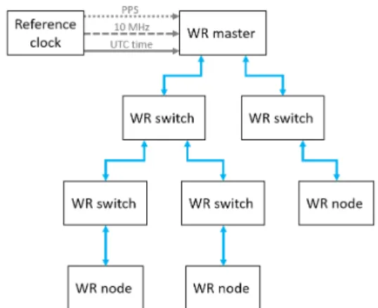
Fig. 1. The WR network architecture.
III. THEWHITERABBITTIMESYNCHRONIZATION PROTOCOL
Recently, the WR protocol, also known as PTP version 3, has been developed and used at CERN to align the clocks of their accelerator complex [8]. The protocol enables the syn-chronization of thousands of devices connected in a network spanning several kilometers through already existing Ethernet-based networks. The accuracy, measured as the deviation of each node with respect to the UTC, achieves the sub-nanosecond, assuming only fiber interconnections. Moreover, the protocol features a reliable and deterministic data delivery. The project is completely open source [19].
These features make the WR an appropriate time synchro-nization protocol for PMU applications. Indeed, the accuracy on 1 ns exceeds the one of synchrophasor needs. Also, the superior determinism with respect to PTP is good for reliability and mission-critical applications. This technology represents an appropriate alternative or complement to the GPS with particular focus on the cases when (i) the sky is not accessible (e.g., urban areas), (ii) the telecommunication infrastructure is already available, and (iii) the typical length between two PMUs is less than 10km (e.g., sub transmission or power distribution networks).
A. The White Rabbit Network Architecture
Figure 1 shows the layout of a typical WR network, that is composed of WR nodes and WR switches, interconnected by fiber or copper links. Data-wise it is a standard Ethernet switched network, i.e. there is no hierarchy: any node can talk to any other node in the network. Regarding time synchroniza-tion, there is a hierarchy, that goes from the top, namely from the WR master, down to other WR switches and consequently nodes. The WR switch, key element of any WR network, is similar to a standard Ethernet switch, but it is also able to precisely distribute the WR master clock over the network thanks to a technique called precise phase measurement.
The uppermost switch in the hierarchy, also called grand-master, receives the absolute clock from an NTP source, together with the pulse-per-second (PPS) and the 10 MHz of an external reference (e.g., the GPS). When rebooting, the WR switch uses the NTP and the PPS to determine the absolute
UTC time. Then, it calculates the time using the 10 MHz signal and it distributes the time information to further WR nodes via intermediate WR switches.
The security of WR against delay-attacks is studied in [18], and countermeasures for this type of attack are proposed.
B. The White Rabbit Synchronization Scheme
The WR is based on existing standards, namely Ethernet (IEEE 802.3) [11], Synchronous Ethernet (SyncE) [12], IEEE 1588 (PTPv2) [9] and adopts a technique called Precise Phase Measurement. The combination of these technologies, further described in this section, enables to achieve the sub-nanosecond accuracy.
1) PTPv2: The same process described in Section II-B holds for calculating the one-way transmission delays. How-ever, in a WR network, PTP messages are managed not only by the grand master clock, but also by the WR switches. This method prevents PTP messages to be exchanged between long links from the master to a far side slave, reducing the unavoidable jitter introduced by each switch. Also, the number of messages between master and slaves is reduced, reducing the PTP-related throughput and allowing more bandwidth for mission-critical data exchange.
2) SynchE: Typical PTP implementations use free-running oscillators in each node, resulting in growing time drifts between master and slaves. This is solved by the SynchE protocol, a technique to transfers the frequency over the Ethernet physical layer, in order to lock all the network nodes to beat at exactly the same rate. Every WR switch uses the clock recovered by the data link to sample the incoming data. Then, it uses an embedded PLL-based oscillator, locked to the recovered clock, for transmission. This procedures ensures high level jitter elimination. Since it acts on the physical layer, its accuracy is independent of data transmission (packet delay or traffic load). The technology has been proven to be able to transfer very accurate timing over long distances [10], [12].
3) Precise Phase Measurement: The accumulation of phase noise degrades the performance of network-based synchro-nization protocols. To this end, every WR switch is equipped with a phase measurement module based on phase/frequency detectors that periodically measures the phase difference be-tween the recovered clock and the master clock [20]. The calculated phase difference is transmitted to a slave node for further compensation of the round-trip link delay with sub-nanosecond accuracy.
IV. INTEGRATION SCHEMES OF TIME REFERENCES INTO A DEDICATEDPMU
In order to compare the performance of the time syn-chronization techniques under investigation, we develop three PMUs based on the same synchrophasor estimation algo-rithm and the same hardware. The only difference among the three is the adopted technique to synchronize to the absolute time reference: the so-called GPS-PMU is based on the GPS time dissemination technique, and is further described in Section IV-A, the PTP-PMU is based on PTPv2 and is described in Section IV-B, whereas the WR-PMU is based on
the WR protocol and its implementation details are given in Section IV-C. The main features of the three devices are very similar to those of the PMU described in [5]: any difference or similarity is further illustrated in the remainder of this section, with a focus on all implementation details that condition time accuracy.
Specifically, the three PMUs are based on the synchrophasor estimation algorithm of [5], an enhanced version of the in-terpolated Discrete Fourier Transform (DFT), hereafter called e-IpDFT, that compensates for the effects of spectral leakage coming from the negative image of the tone under analysis. Such PMU is compliant with all requirements of the IEEE Std. C37.118.1 [1] for P-class PMUs.
In order to estimate the synchrophasors, the PMU acquires a discrete time-series of samples, defined as follows:
x[n] :={x(tn) | tn=nTs, n= [0, . . . N−1]∈N} (3) where x(t) is the time-variant power system signal under analysis, N is the number of samples that compose the considered windowx[n] andFs=Ts−1 is the sampling rate. Given x[n], the synchrophasor extraction algorithm retrieves estimated frequencyfˆ, rate-of-change-of-frequency (ROCOF), amplitudeAˆand initial phase angleϕˆ0of the fundamental tone of the signal under analysis. The measurements are reported by the PMU with a given reporting rate Fr and are time-tagged with the so-called time-stamp. It is worth pointing out that the e-IpDFT adopts a 60 ms window T, a 50 kHz sampling frequency (leading to 3000-points windows) and that the reporting frequency is set to 50 frames per second (fps).
As in [5], the hardware platform of the three devices is based on the National Instruments compactRIO (cRIO) system, an embedded industrial controller with a real-time processor, a user-programmable Field Programmable Gate Array (FPGA) and reconfigurable IO modules. It is worth to point out that in the designed architecture, the three main processes, i.e., (i) PMU time synchronization, (ii) signal acquisition and (iii) synchrophasor estimation, run at the FPGA level. Indeed, FPGAs provide hardware-timed speed and reliability, that are two essential features for synchrophasor applications.
The sampling of the voltage and current waveforms is real-ized by means of two parallel 24-bits deltasigma converters, module NI 9225 and 9227 respectively, characterized by a sampling rate Fs of 50 kHz and an input range of 300 VRMS for the voltage and 5 ARMS for the current.
Regardless of the adopted time dissemination technique, the sampling process of the waveforms is free-running and the UTC-time synchronization is achieveda posteriori1. Specifi-cally, at the FPGA level, we derive form the UTC-PPS signal a sub PPS square waveform (hereafter called subPPS), locked to the UTC-PPS and characterized by a frequency correspond-ing to the PMU reportcorrespond-ing rate Fr. The signal acquisition, the synchrophasor estimation, and the synchrophasor time-stamping are triggered by the rising edge of such subPPS. However, there is no guarantee that the sampling process is
1A different approach could be adopted, where the synchronization of the
sampling process to the UTC-time is performed on-line by means of dedicated phase-locked loop circuitry. However, that would make the overall system architecture more complex.
locked to such subPPS signal: there must be an a posteriori
time refinement.
Specifically, two delays need to be compensated. The first one results from the fact that the sampling frequency might drift from its nominal value, due to oscillator degradation or environment conditions variation (such as temperature). We measure this frequency drift over observation windows of M
samples, withM >> N(such as few seconds windows). If the sampling process was uniform, such window would account for an ideal amount of timeM Ts. In real operating conditions, the actual difference between the time instant when the last sample is acquired tM−1 and the time instant when the first sample is acquired t0, might differ from the ideal delay. The clock drift is defined as the normalized difference between these two delays:
fD=
(tM−1−t0)−M Ts M Ts
(4) Every time the clock drift is updated, the DFT frequency resolution∆f = 1/T can be adequately compensated as
∆fc= ∆f(1−fD) (5) and therefore the frequency estimation improvedfˆc.
The second delay is due to the possible offset between the two clocks. Indeed, in ideal operating conditions, i.e., if the sampling process was locked to the subPPS, the time delay between the rising edge of the subPPStsubP P Sand the time instant when the first sample of the related window is acquiredt0would be exactly zero. In real operating conditions, there could be a delay that would result in bad initial phase estimations. We measure this time delay at every subPPS and compensate for it by updating the estimated phase as follows:
ˆ
ϕ0,c= ˆϕ0+ 2πfˆc(t0−tsubP P S) (6)
A. GPS Time Synchronization
The GPS-PMU is based on the cRIO-9068 controller, embedding a reconfigurable Xilinx Zynq 7020 FPGA with an on-board clock frequency of 40 MHz, 106400 flip-flops, 53200 look-up tables (LUTs), 4480 kbits of block RAM and 220 DSP slices (each one characterized by a 25 X 18 multiplier, an adder and an accumulator). The UTC-GPS signal is acquired by means of the NI 9467 GPS time-stamping and synchronization module, that is directly coupled with the on-board FPGA clock. This enables to timestamp each tick of the 40 MHz clock with real-world time, accurate to within
± 100 ns. That is to say that the NI GPS module provides a continuous time reference characterized by a time polling resolution corresponding to the FPGA clock. The subPPS is locked to the UTC-GPS.
The GPS module is coupled with a Trimble’s Bullet III GPS receiver, an active GPS antenna with a high-gain preamplifier (35 dB) and dual passband filters. The preamplifier enables preserving the GPS signal even for long cable lengths, whereas the filters improve rejection to interfering radio signals and reliability. The antenna is mounted on the rooftop of DESL laboratory with a full-sky visibility and is coupled to the module via a 30-meters RG-213 shielded cable. The latter,
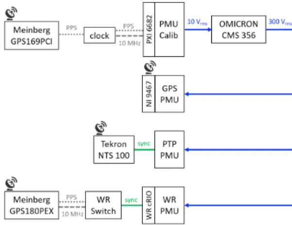
Fig. 2. The experimental WR network composed of a Meinberg GPS180PEX card, a WR switch and a NI-cRIO integrating the WR-cRIO module (i.e., a WR-PMU).
introduces un unavoidable propagation delay of 5.05 ns/m, leading to 151.5 ns (suitably compensated).
B. PTP Time Synchronization
The PTP-PMU is based on the cRIO-9039 controller, char-acterized by a reconfigurable Xilinx Kintex-7 FPGA with an on-board clock frequency of 40 MHz, 407600 flip-flops, 203800 look-up tables (LUTs), 16020 kbits of block RAM and 840 DSP slices. The PTP distribution is achieved thanks to the NI TimeSync library, that synchronizes the timekeeping clocks of the cRIO. The so-called hardware time-stamping enables to discipline the FPGA clock directly via the UTC-PTP reference. This enables to timestamp each tick of the 40 MHz clock with real-world time, accurate to within ±1 µs. The TimeSynch library provides a continuous time reference, however, since the FPGA clock is locked to the UTC-PTP, the resolution of time stamps corresponds to 25 ns.
The UTC-PTP reference signal is acquired by connecting point-to-point the three-speed RJ-45 Gigabit Ethernet Port to a PTP master clock. The latter is the Network Time Server NTS 100 manufactured by Tekron. The clock receives the absolute time reference by a Trimble’s Bullet III GPS receiver, whose characteristics have been already discussed in Section IV-A.
C. White Rabbit Time Synchronization
The WR-PMU setup is shown in Fig. 2, and is based on the same hardware platform as the GPS-PMU, i.e., cRIO-9068. The WR-UTC signal is provided by the NI WR cRIO module, a standalone WR node which can be coupled with the NI cRIO platforms to integrate the WR protocol [21]. The module is equipped with a Xilinx Spartan-6 FPGA and can be used in all operation modes defined by the WR protocol, i.e., grand-master, master or slave. Depending on the selected operation mode, a different configuration of input and outputs shall be adopted. A user programmable HDSUB-15 I/O module is provided, that can acquire the 10 MHz and PPS inputs (in case of operating the node in grand-master mode) or any sort of external trigger, as well as generate reference clock, PPS outputs or generic triggers. The module is also equipped with a Small Form-factor Pluggable (SFP) cage, for disseminating WR messages over optic fiber transceivers. In particular, when operated in slave mode, such cage is used to connect the module to its master WR switch and to retrieve the time information.
In the developed PMU, the module is operated in slave mode, and is connected point-to-point to a WR switch operated in grand-master mode. The switch is manufactured by Seven Solutions. Ethernet frames are exchanged through 18 ports equipped with SFP sockets, connected directly to a Xilinx Virtex-6 FPGA characterized by very low latency. An ARM CPU running Linux helps with less time-sensitive processes like remote management and keeping the frame filtering database in the FPGA up to date. The clocking resources block contains PLLs for cleaning up and phase-compensating the system clock, as well as for generating the frequency-offset clock. It provides deterministic delivery and a reliable communication using redundant network topology. It allows many hops (14 tested keeping subnanosecond accuracy).
The NTP service, used to determine the absolute time and date at reboot, is provided by a Windows machine connected point-to-point to the RJ-45 management port of the WR switch via an Ethernet cable. The Windows machine is equipped with a Meinberg 180 PEX card that disciplines the system time as well as the NTP service. The card is coupled with an active GPS receiver, mounted on the rooftop of DESL laboratory, via a 30-meters RG-213 shielded cable. The card compensates for the delay introduced by the cable (as already discussed in Section IV-A). The card further generates reference PPS and 10 MHz signals, that are fed to the WR switch.
Due to hardware limitations, the UTC-WR polling is limited by the module’s FPGA clock running at 50 kHz, therefore, the WR cRIO does not provide a continuous time reference. Also, the UTC-WR reading introduces a deterministic delay, that needs to be compensated. The next paragraph describes the implementation details that enable us to overcome these two limitations.
1) On the Retrieving of the WR Time: To retrieve the UTC-WR from the UTC-WR cRIO, we generate a trigger characterized by a frequency of 50 kHz, i.e., the maximum value attainable in the WR cRIO FPGA. The procedure illustrated in Algorithm 1 is implemented to trigger the UTC-WR acquisition, to freeze the time, and to acquire it. Specifically, when the state is Algorithm 1 Retrieving the WR time.
1: WhileTrue
2: Go to normal operation 3: Start
4: WhileTtrig
5: Wait for node start 6: end
7: Read UTC-WR 8: Idle
9: end
Wait for Node Start, the trigger is generated and the WR cRIO acquires the reference time. The UTC-WR is frozen and acquired in the next states. Then the node is set in Idle
mode until the next trigger. The time acquisition process is not continuous but the UTC-WR is updated in a discrete manner, determined by the trigger periodTtrig of 20µs. This lower bound is limited by the FPGA integrated in the NI
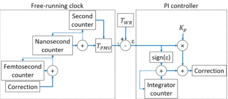
Fig. 3. The structure of the internal clock regulated by the PI controller.
cRIO, characterized by a finite and deterministic time polling resolution, not appropriate for PMU applications.
To overcome this hardware limitation, an additional internal free-running clock is implemented. Such clock is disciplined by the FPGA clock and is implemented at every tick, i.e., every 25 ns. As long as the UTC-WR is not updated, the free-running clock governs the PMU time. Every time the UTC-WR is acquired, the free-running clock is overwritten by the updated reference time.
As it is known, the FPGA clock could drift even in the short interval between two consecutive triggers, biasing the attainable sub-nanosecond accuracy. Therefore, every time the UTC-WR is acquired, the deviation between the free-running clock and the UTC-WR is computed, and this error is used by a PI controller to condition the free-running clock.
The structure of the free-running clock and its PI controller is shown in Fig. 3: the PMU time is made of the second and nanosecond counters and the correction γ(n) is added to a femtosecond counter at each tick. The PMU time is therefore corrected only when this counter has an overflow or an underflow. The tuning of the PI controller has been done empirically: the proportional coefficient Kp has been chosen to average the error entering the PI controller over a period of 10 ms, which gives a very low jitter. The integrator is built as a counter that is incremented or decremented according to the sign of the error. Its resolution has been set to 1 fs (i.e. the highest possible), which allows to compensate the steady-state error without introducing additional jitter. The implemented internal clock is explained in Algorithm 2.
Algorithm 2 Internal free-running clock. 1: if TW R(n)6=TW R(n−1) 2: ε(n) =TW R(n)−TP M U(n) 3: γ(n) =Kpε(n) +P n 0sign(ε(k)) 4: end 5: TP M U(n) =TP M U(n) + ∆T+γ(n)
It is worth noting that, due to hardware limitations, there is a delay in acquiring the UTC-WR. However, the use of the FPGA makes this delay time-deterministic (in the order of few microseconds) and, therefore, enables the free-running clock to compensate for it (see Fig. 4).
In addition to greater resolution, the internal free-running clock also has much less jitter than the WR time, as shown
Fig. 4. The structure of the internal conditioned clock together with theTW R.
TABLE I
PERFORMANCE OFTW RANDTP M U. TW R TP M U
Jitter [ns] 2.89 0.42
in Table I. The calculation of jitter is done by computing the time steps of the WR time TW R and the PMU clock TP M U (i.e., WR time together with the internal free-running clock) between two successive triggers Ttrig. The standard deviation is then computed with 1000 samples. The performance of this implementation, characterized by the jitter, is appropriate for a PMU application.
V. PERFORMANCEASSESSMENT
The performance of the described PMUs is assessed by means of the dedicated PMU calibrator described in [13], [14], that enables us to validate the conformity of the PMU under test with respect to the IEEE Std. C37.118 [1]. The calibrator, generates reference signals whose true parameters are known with a TVE in the order of 10−4%, obtained in case of static signals. The true parameters are determined by the well-known Levenberg-Marquardt algorithm, based on a nonlinear least-squares method. Such procedure, described in [22], has been proven to provide a unique and robust solution within the whole range of static tests required by [1].
The forward path of the calibrator generates a set of static reference waveforms characterized by a sampling rate of 500 kHz, peak amplitude of 10 V, 0 rad phase and frequency varying in the range [47.5, 52.5] Hz (i.e., the PMU pass-band). These signals are amplified by a CMS-356 OMICRON precision voltage and current amplifier, characterized by an amplification gain of 30, and simultaneously acquired by the three PMUs under test (see Fig. 5). The final waveforms are characterized by a signal-to-noise-ratio (SNR) of 85 dB.
As known, the uncertainty requirements are expressed in terms of TVE, Frequency Error (FE), and ROCOF Error (RFE). However, the analysis of amplitude and phase error
Fig. 5. Performance assessment scheme.
TABLE II
STANDARD DEVIATION(1σ)OF ABSOLUTE PHASE ERROR. Frequency GPS-PMU PTP-PMU WR-PMU
[Hz] [µrad] [µrad] [µrad]
47.5 11.3 12.3 7.8
50 18.1 25.9 8.1
52.5 13.3 15.7 7.1
separately provides a deeper understanding about eventual error sources. More specifically, every inaccuracy related to a poor time-synchronization of the PMU under test, expresses itself in a phase error. Also, since the phasor estimation algorithm and the hardware platform is identical for the three PMUs, the time synchronization protocol mainly affects the phase estimation.
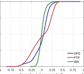
The test has been conducted by coupling for several days the three devices with the PMU calibrator, generating a steady state signal at 50 Hz. Then, for each time source, we have selected the 24 hours that resulted in the worst case phase error. This choice enables us to study the maximum phase error introduced by the time dissemination, that finally defines its accuracy. Figure 6 shows the cumulative distribution function (CDF) of the unbiased normalized phase errors2 for the three PMUs and for the three selected days.
Then, we have conducted a further test aimed at demon-strating the phase estimation consistency at different frequency levels. This case refers to a reference signal at 47.5 and 52.5 Hz for 24 hours. Table II shows the standard deviation of the phase errors of the three PMUs. It is worth to point out that the data at 50 Hz in both Fig. 6 and Table II refer the worst 24 hours registered over an observation window of several days.
As shown in Fig. 6, the three PMUs are characterized by different trends of the distribution of the absolute phase error. As expected, the PTP-PMU is characterized by the most disperse distribution, with a standard deviation of 26 µrad. The WR-PMU exhibits the sharpest CDF trend with σ = 8
µrad, demonstrating that such synchronization technique is
2We normalize the phase error by its mean value calculated in the
considered observation interval. By doing so, we focus our analysis on the standard deviation of the phase error. Indeed, any absolute phase discrepancy can be properly compensated at the PMU output.
-1 -0.75 -0.5 -0.25 0 0.25 0.5 0.75 1
Normalized phase error [rad] 10-4
0 25 50 75 100 CDF [%] GPS PTP WR
Fig. 6. CDF of the phase error at 50 Hz over 24 hours.
the most deterministic one. The GPS-PMU is characterized by non symmetric tails and a non-null mean value (σ= 18µrad), because the time evolution of the phase errors is characterized by a non symmetric trend.
In general, the results in Fig. 6 reflect the accuracy specifi-cation of the adopted time synchronization techniques, in the sense that the lower the accuracy of the timing module, the more disperse the phase error distribution. However, due to the presence of noise characterizing the analyzed waveforms, the expected phase accuracies of the three PMUs are closer. Indeed, at 85 dB of SNR the adopted synchrophasor estimation algorithm has a theoretical minimum phase accuracy that is in the order of 5 µrad, obtained for a simulated waveform in steady state conditions. For the WR-PMU, the noise in-troduced by the algorithm is dominating and masking the potential improvement of the phase estimate given by this technology. However, an improvement of 10 µrad is achieved for the WR-PMU with respect to the GPS counterpart. Table II further demonstrates that WR is characterized by the smallest error in every test condition and at every frequency level.
VI. CONCLUSION
The paper presented the use of the WR time synchronization protocol for synchrophasor networks. The WR is characterized by a time accuracy of 1 ns, that is superior to those of state-of-the-art time dissemination technologies used for PMU applications, i.e., 100 ns for GPS and 1 µs for PTP.
The IEEE Std. C37.118.1 requires a maximum synchroniza-tion uncertainty of 1 µs for PMUs operating in transmission networks [1], but this value is lowered to 10 ns for distribution PMUs [3]. Therefore, the WR is a suitable time distribution technique for PMUs operating at any power system level.
The paper has presented the integration of the WR protocol in a specifically developed WR-PMU, and has assessed its performance with respect to a GPS-PMU and a PTP-PMU. The three PMUs are characterized by the same synchrophasor estimation algorithm and by the same hardware platform,
with the exception of the time synchronization technique. The results demonstrate the advantage of using the WR instead of GPS, as it is characterized by a more deterministic phase error, experimentally quantified in 8µrad.
REFERENCES
[1] “IEEE standard for synchrophasor measurements for power systems,” IEEE Std C37.118.1-2011 (Revision of IEEE Std C37.118-2005), pp. 1–61, Dec 2011.
[2] M. Pignati, L. Zanni, S. Sarri, R. Cherkaoui, J.-Y. Le Boudec, and M. Paolone, “A pre-estimation filtering process of bad data for linear power systems state estimators using PMUs,” inPower Systems Com-putation Conference (PSCC), 2014, Aug 2014, pp. 1–8.
[3] “Time synchronization in the electric power system,” NASPI Time Synchronization Task Force, 2017.
[4] “Synchrophasor monitoring for distribution systems: Technical founda-tions and applicafounda-tions,”NASPI Distribution Task Team, 2018. [5] P. Romano and M. Paolone, “Enhanced interpolated-DFT for
syn-chrophasor estimation in FPGAs: Theory, implementation, and valida-tion of a PMU prototype,”IEEE Transactions on Instrumentation and Measurement, vol. 63, no. 12, pp. 2824–2836, Dec 2014.
[6] X. Jiang, J. Zhang, B. J. Harding, J. J. Makela, A. D. Domı et al., “Spoofing GPS receiver clock offset of phasor measurement units,”IEEE Transactions on Power Systems, vol. 28, no. 3, pp. 3253–3262, 2013. [7] S. B. Andrade, M. Pignati, G. Dan, M. Paolone, and J. Y. L. Boudec,
“Undetectable PMU timing-attack on linear state-estimation by using rank-1 approximation,” IEEE Transactions on Smart Grid, vol. PP, no. 99, pp. 1–1, 2017.
[8] J. Serrano, P. Alvarez, M. Cattin, E. G. Cota, P. M. J. H. Lewis, T. Włostowski et al., “The white rabbit project,” in Proceedings of ICALEPCS TUC004, Kobe, Japan, 2009.
[9] “IEEE Standard for a Precision Clock Synchronization Protocol for Networked Measurement and Control Systems,” IEEE Std 1588-2008 (Revision of IEEE Std 1588-2002), pp. 1–300, July 2008.
[10] M. Lipi´nski, T. Włostowski, J. Serrano, and P. Alvarez, “White rabbit: a PTP application for robust sub-nanosecond synchronization,” in2011 IEEE International Symposium on Precision Clock Synchronization for Measurement, Control and Communication, 2011, p. 2530.
[11] “IEEE Standard for Ethernet,”IEEE Std 802.3-2015 (Revision of IEEE Std 802.3-2012), pp. 1–4017, March 2016.
[12] “Timing Characteristics of Synchronous Ethernet Equipment Slave Clock (EEC),”ITU-T Rec. G.8262, August 2007.
[13] D. Colangelo, L. Zanni, M. Pignati, P. Romano, M. Paolone, J.-P. Braun, and L.-G. Bernier, “Architecture and characterization of a calibrator for PMUs operating in power distribution systems,” in 2015 IEEE Eindhoven PowerTech, June 2015, pp. 1–6.
[14] G. Frigo, A. Derviˇskadi´c, D. Colangelo, J.-P. Braun, and M. Paolone, “Characterization of uncertainty contributions in a high-accuracy PMU validation system,”Measurement, 2018.
[15] R. Razzaghi, A. Derviˇskadi´c, and M. Paolone, “A white rabbit synchro-nized PMU,” in2017 IEEE PES Innovative Smart Grid Technologies Conference Europe (ISGT-Europe), Sept 2017, pp. 1–6.
[16] P. Romano, “DFT-based synchrophasor estimation algorithms and their integration in advanced phasor measurement units for the real-time monitoring of active distribution networks,” EPFL PhD dissertation, 2016.
[17] D. Mills, J. Martin, J. Burbank, and W. Kasch, “Network time protocol version 4: Protocol and algorithms specification,” Tech. Rep., 2010. [18] A. S. S. Barreto and J. Y. L. Boudec, “Cyber-attack on packet-based
time synchronization protocols: The undetectable delay box,”2016 IEEE International Instrumentation and Measurement Technology Conference Proceedings, pp. 1–6, 2016.
[19] CERN, “The White Rabbit Project,” 2017, accessed: 2018-08-10. [Online]. Available: http://white-rabbit.web.cern.ch/
[20] G. Daniluk and T. Włostowski, “White rabbit: Sub-nanosecond syn-chronization for embedded systems,” inProceedings of the 43rd Annual Precise Time and Time Interval Systems and Applications Meeting, Nov 2011.
[21] “CompactRIO white rabbit (CRIO-WR),” accessed: 2018-03-09. [Online]. Available: https://www.ohwr.org/projects/crio-wr/wiki [22] G. Frigo, D. Colangelo, A. Derviˇskadi´c, M. Pignati, C. Narduzzi,
and M. Paolone, “Definition of accurate reference synchrophasors for static and dynamic characterization of PMUs,” IEEE Transactions on Instrumentation and Measurement, vol. 66, no. 9, pp. 2233–2246, Sept 2017.