ASHRAE STANDARD
ASHRAE STANDARD
BACnet
®
—A Data
Communication
Protocol for Building
Automation and
Control Networks
Approved by the ASHRAE Standards Committee on January 23, 2010; by the ASHRAE Board of Directors on January 27, 2010; and by the American National Standards Institute on January 28, 2010.
This standard is under continuous maintenance by a Standing Standard Project Committee (SSPC) for which the Standards Committee has established a documented program for regular publication of addenda or revi-sions, including procedures for timely, documented, consensus action on requests for change to any part of the standard. The change submittal form, instructions, and deadlines may be obtained in electronic form from the ASHRAE Web site, http://www.ashrae.org, or in paper form from the Manager of Standards. The latest edi-tion of an ASHRAE Standard may be purchased from ASHRAE Customer Service, 1791 Tullie Circle, NE, Atlanta, GA 30329-2305. E-mail: orders@ashrae.org. Fax: 404-321-5478. Telephone: 404-636-8400 (world-wide), or toll free 1-800-527-4723 (for orders in US and Canada).
© Copyright 2010 American Society of Heating, Refrigerating and Air-Conditioning Engineers, Inc.
ISSN 1041-2336
American Society of Heating, Refrigerating
and Air-Conditioning Engineers, Inc.
1791 Tullie Circle NE, Atlanta, GA 30329
www.ashrae.org
SPLS Liaison: Douglas T. Reindl
*Denotes members of voting status when the document was approved for publication
David Robin, Chair* Daniel P. Giorgis Carl J. Ruther
Carl Neilson, Vice-Chair David G. Holmberg David G. Shike
Sharon E. Dinges, Secretary* Bernhard Isler* Ted Sunderland
Donald P. Alexander* Robert L. Johnson William O. Swan, III
Barry B. Bridges* Stephen Karg* David B. Thompson*
Coleman L. Brumley, Jr.* Simon Lemaire Daniel A. Traill
Ernest C. Bryant J. Damian Ljungquist* Stephen J. Treado*
A. J. Capowski James G. Luth J. Michael Whitcomb*
John J. Lynch
ASHRAE STANDARDS COMMITTEE 2009–2010
Steven T. Bushby, Chair
H. Michael Newman, Vice-Chair
Robert G. Baker Michael F. Beda Hoy R. Bohanon, Jr. Kenneth W. Cooper K. William Dean Martin Dieryckx Allan B. Fraser Katherine G. Hammack Nadar R. Jayaraman Byron W. Jones Jay A. Kohler Carol E. Marriott Merle F. McBride Frank Myers Janice C. Peterson Douglas T. Reindl Lawrence J. Schoen Boggarm S. Setty Bodh R. Subherwal James R. Tauby James K. Vallort William F. Walter Michael W. Woodford Craig P. Wray Wayne R. Reedy, BOD ExO
Thomas E. Watson, CO Stephanie Reiniche, Manager of Standards
SPECIAL NOTE
This American National Standard (ANS) is a national voluntary consensus standard developed under the auspices of the American Society of Heating, Refrigerating and Air-Conditioning Engineers (ASHRAE). Consensus is defined by the American National Standards Institute (ANSI), of which ASHRAE is a member and which has approved this standard as an ANS, as “substantial agreement reached by directly and materially affected interest categories. This signifies the concurrence of more than a simple majority, but not necessarily unanimity. Consensus requires that all views and objections be considered, and that an effort be made toward their resolution.” Compliance with this standard is voluntary until and unless a legal jurisdiction makes compliance mandatory through legislation.
ASHRAE obtains consensus through participation of its national and international members, associated societies, and public review. ASHRAE Standards are prepared by a Project Committee appointed specifically for the purpose of writing the Standard. The Project Committee Chair and Vice-Chair must be members of ASHRAE; while other committee members may or may not be ASHRAE members, all must be technically qualified in the subject area of the Standard. Every effort is made to balance the concerned interests on all Project Committees.
The Manager of Standards of ASHRAE should be contacted for: a. interpretation of the contents of this Standard,
b. participation in the next review of the Standard,
c. offering constructive criticism for improving the Standard, or d. permission to reprint portions of the Standard.
DISCLAIMER
ASHRAE uses its best efforts to promulgate Standards and Guidelines for the benefit of the public in light of available information and accepted industry practices. However, ASHRAE does not guarantee, certify, or assure the safety or performance of any products, components, or systems tested, installed, or operated in accordance with ASHRAE’s Standards or Guidelines or that any tests conducted under its Standards or Guidelines will be nonhazardous or free from risk.
ASHRAE INDUSTRIAL ADVERTISING POLICY ON STANDARDS
ASHRAE Standards and Guidelines are established to assist industry and the public by offering a uniform method of testing for rating purposes, by suggesting safe practices in designing and installing equipment, by providing proper definitions of this equipment, and by providing other information that may serve to guide the industry. The creation of ASHRAE Standards and Guidelines is determined by the need for them, and conformance to them is completely voluntary.
In referring to this Standard or Guideline and in marking of equipment and in advertising, no claim shall be made, either stated or implied, that the product has been approved by ASHRAE.
ANSI/ASHRAE Addendum y to ANSI/ASHRAE Standard 135-2008 1 [This foreword and the “rationale” on the following pages are not part of this standard. They are merely informative and do not contain requirements necessary for conformance to the standard.]
FOREWORD
Addendum 135y to ANSI/ASHRAE Standard 135-2008 contains a number of changes to the current standard. These modifications are the result of change proposals made pursuant to the ASHRAE continuous maintenance procedures and of deliberations within Standing Standard Project Committee 135. The changes are summarized below.
135-2008y-1. Specify Deployment Options for MS/TP, p. 2.
In the following document, language added to existing clauses of ANSI/ASHRAE 135-2008 and addenda is indicated through the use of italics, while deletions are indicated by strikethrough. Where entirely new subclauses are added, plain type is used throughout.
2 ANSI/ASHRAE Addendum y to ANSI/ASHRAE Standard 135-2008
135-2008y-1 Specify Deployment Options for MS/TP.
Rationale
Although EIA RS-485 practice allows for a third wire to connect transceiver common or reference points together so the receiver common mode rejection voltage limit is not exceeded, the BACnet specification in Clause “9.2.1 Medium” only mentions “shielded, twisted-pair cable.”
Due to electrical noise issues, some hardware applications cannot successfully communicate over EIA RS-485 without a remote common or reference connection and internal isolation. This has been particularly noticed in variable speed drive controllers that can produce local ground noise in excess of the EIA-485 common mode voltage limit.
BACnet MS/TP also requires 1500-volt isolation when crossing buildings, but does not specify any mechanism for doing this.
This proposed change is designed to describe wiring topologies for a reference wire in EIA RS-485 and to specify acceptable topologies for interoperable connections for both single-building and multiple-building installations.
[Change 9.2.1 Medium, p. 74] 9.2.1 Medium
An MS/TP EIA-485 network shall use shielded, twisted-pair cable for data signaling with characteristic impedance between 100 and 130 ohms. In addition to the twisted pair, an additional conductor may be used for common or signal reference if required by the particular device. Distributed capacitance between conductors shall be less than 100 pF per meter (30 pF per foot). Distributed capacitance between conductors and shield shall be less that 200 pF per meter (60 pF per foot). Foil or braided shields are acceptable. The maximum recommended length of an MS/TP segment is 1200 meters (4000 feet) with AWG 18 (0.82 mm2 conductor area) cable. The use of greater distances and/or different wire
gauges shall comply with the electrical specifications of EIA-485. [Insert new clause 9.2.2.1 Device Wiring with subclauses, p. 75]
9.2.2.1 Device Wiring
There are a variety of permitted device wiring arrangements, depending on the particular needs of the devices used and the installation requirements. Some MS/TP devices are designed with a third-wire Reference connection in addition to the signaling connections and some are two-wire only, depending on the particular application being addressed. All device wiring arrangements shall meet the Connections and Terminations restrictions and requirements described in Clause 9.2.2.
9.2.2.1.1 Single Buildings
Within a single building, there is generally a limited ground voltage offset from one MS/TP device to another, thus permitting a simple installation in most cases. The following clauses describe several common methods for wiring devices within a single building using different device wiring arrangements.
9.2.2.1.1.1 Twisted-pair Only with Non-isolated Devices
For many installations, a simple twisted pair wire with shield is sufficient to allow reliable communications. In Figure 9-1.1, all of the devices use two-wire connections with the reference level between devices established by an internal earth ground connection made through some impedance (Z) at each device. This is generally the lowest cost solution and is sufficient for installations where electrical noise, ground noise, and stray fields are low. EIA-485 is designed to operate with voltages on the signaling wires between -7 and +12 volts. If the voltage between any two earth ground connections combined with the noise picked up by the twisted pair signaling wire is well within this range, the EIA-485 requirements for signaling levels have been met.
ANSI/ASHRAE Addendum y to ANSI/ASHRAE Standard 135-2008 3
Figure 9-1.1. Simple Twisted Pair with Shield. 9.2.2.1.1.2 Twisted-pair Only with Mixed Devices
Some EIA-485 devices provide a third-wire reference connection and use internal isolation. The third-wire reference shall be electrically connected to the other devices’ reference to meet EIA-485 requirements. When such a device is used in a low-electrical-noise installation, it is sufficient to connect the third-wire reference to earth using a 100 ohm current limiting resistor (R) as shown in Figure 9-1.2. The earth connection may be made using either the shield of the communication cable since it is tied to earth ground at one point (this is the preferred approach) or a local earth grounding point such as the device case. This type of connection does not take full advantage of the electrical noise rejection capability of the third-wire reference.
4 ANSI/ASHRAE Addendum y to ANSI/ASHRAE Standard 135-2008
Figure 9-1.2. Mixed Devices on Twisted Pair with Shield. 9.2.2.1.1.3 Twisted-pair and Reference with Isolated Devices
If the installation exclusively uses EIA-485 devices with third-wire reference connections, electrical noise rejection is best if a third conductor in the same cable is used to connect all of the reference connections together as shown in Figure 9-1.3. This nearly eliminates earth-ground voltage differences and allows the differential input of each EIA-485 device to float with the electrical noise and stray fields picked up by the signal cable, resulting in better noise rejection. If there are more than three wires in the cable chosen, the third conductor shall be made up of all of the extra wires (outside of the twisted pair used for signaling) connected together. If desired, the third-wire reference conductor may be tied to earth ground at one point where electrical noise is low through a 100-ohm current-limiting resistor in order to limit voltage excursions and to simplify adding two-wire devices in the future.
ANSI/ASHRAE Addendum y to ANSI/ASHRAE Standard 135-2008 5
+
Internal Data Twisted Pair Shield+
Internal Data+
Internal Data REFISOLATED ISOLATED ISOLATED
Figure 9-1.3. All Isolated Devices on 3-Conductor Cable with Shield. 9.2.2.1.1.4 Twisted-pair and Reference with Mixed Devices
If the installation includes a mixture of two-wire non-isolated devices and three-wire isolated devices, they may be used together in the configuration of Figure 9-1.4 if the two-wire devices are installed in areas with low electrical noise or if high levels of electrical noise are generated locally at the three-wire isolated devices and the remainder of the installation is electrically quiet. In this installation, a third conductor in the same cable is used to connect all of the reference connections together. Three-wire devices with a reference connection shall be directly tied to the third conductor and two-wire device reference connections are made indirectly through a single 100-ohm current-limiting resistor tied between the reference conductor and earth ground in a low-noise area, preferably near the supervisory controller.
6 ANSI/ASHRAE Addendum y to ANSI/ASHRAE Standard 135-2008
Figure 9-1.4. Mixed Devices on 3-Conductor Cable with Shield. 9.2.2.1.1.5 Extending Twisted-pair with Reference
If the installation includes existing two-wire non-isolated devices that are to be extended with three-wire isolated devices, they may be connected together in the configuration of Figure 9-1.5. In this installation, a third conductor in the extended cable is used to connect all of the reference connections together. Three-wire devices with a reference connection shall be directly tied to the third conductor and two-wire device reference connections are made indirectly through a single 100-ohm current-limiting resistor tied between the reference conductor and earth ground in a low noise area, preferably where the extended cable is connected to the existing twisted-pair cable.
ANSI/ASHRAE Addendum y to ANSI/ASHRAE Standard 135-2008 7
Figure 9-1.5. Extending Existing Twisted-pair with Isolated Devices. 9.2.2.1.2 Multiple Buildings
Connecting multiple buildings using MS/TP shall have at least 1500 V of electrical isolation as specified in Clause 9.2.2. The following clauses describe ways to provide the required isolation.
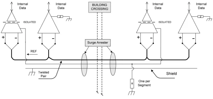
9.2.2.1.2.1 Isolated Devices
Installations that connect multiple buildings using a single cable are permitted if the secondary buildings contain only three-wire isolated devices with 1500-volt electrical isolation capability and there are no earth ground connections in the secondary buildings to the reference conductor or the shield as shown in Figure 9-1.6. When the primary building contains only two-wire non-isolated devices, the reference conductor shall be connected to earth ground at one location through a 100-ohm current-limiting resistor (R) in that building and the shield shall be tied to earth ground in a single location in the same building. The use of surge arrestors near each building’s cable entrance to protect all of the conductors is recommended.
8 ANSI/ASHRAE Addendum y to ANSI/ASHRAE Standard 135-2008
Figure 9-1.6. Two Buildings with All Isolated Devices in One Building. 9.2.2.1.2.2 Isolated Repeater
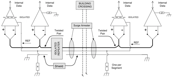
If the installation includes a mixture of three-wire isolated and two-wire non-isolated devices in each of two buildings on a single communications line, it is possible to connect the buildings using an isolated repeater so that each building is electrically isolated from the other building as shown in Figure 9-1.7. The isolated repeater must provide complete three-way electrical isolation between the wiring on either side and ground. In this case, the communication wiring within each building is configured like that of a single building since the isolated repeater provides the required 1500-volt electrical isolation. The cable connecting the buildings is an extension of the cable in one of the buildings and shall be electrically isolated from the other building by the isolated repeater and shall not have any connections to other devices or to ground within the other building.
An isolated repeater may also be used on both sides of the cable connecting the buildings. This may be needed for extra isolation or for cable length. In this case the cable connecting the buildings shall be separately shielded, terminated, and biased and shall not have any connections to other devices within either building. If the pair of isolated repeaters provides a reference connection, the two reference connections shall be joined by a third conductor within the cable connecting the buildings and shall not be connected to any other device or to ground.
ANSI/ASHRAE Addendum y to ANSI/ASHRAE Standard 135-2008 9 Twisted Pair REF BUILDING CROSSING
+
-Data ISOLATED+
-Data Z+
-Data Z+
-Data ISOLATED ISOL ATED REPE ATER Surge Arrester REF Twisted Pair RR Shield SegmentOne per
Figure 9-1.7. Isolated Repeater between Two Buildings with Surge Arresters. 9.2.2.1.2.3 Fiber Optic Isolation
If the installation includes a mixture of three-wire isolated and two-wire non-isolated devices in each of two buildings on a single communications line, it is best to connect the buildings using EIA-485 half-duplex compatible fiber optic modems so that each building is electrically isolated from the other building and there are no conductors outside the buildings as shown in Figure 9-1.8. In this case, the communication wiring within each building is configured like that of a single building since the fiber optic modems provide the required 1500-volt electrical isolation.
10 ANSI/ASHRAE Addendum y to ANSI/ASHRAE Standard 135-2008
9.2.2.1.2.4 No Isolation (not permitted)
Directly connecting two buildings with a single EIA-485 communications cable where there are two-wire non-isolated devices in each building shall not be permitted since the required 1500-V electrical isolation between signal conductors and digital ground cannot be maintained. Device wiring such as that shown in Figure 9-1.9 is not allowed.
ANSI/ASHRAE Addendum y to ANSI/ASHRAE Standard 135-2008 11 [Add a new entry to History of Revisions, p. 688]
(This History of Revisions is not part of this standard. It is merely informative and does not contain requirements necessary for conformance to the standard.)
HISTORY OF REVISIONS
Protocol Summary of Changes to the Standard
Version Revision
… … …
1 10 Addendum y to ANSI/ASHRAE 135-2008
Approved by the ASHRAE Standards Committee January 23, 2010; by the ASHRAE Board of Directors January 27, 2010; and by the American National Standards Institute January 28, 2010.
ASHRAE is concerned with the impact of its members’ activities on both the indoor and outdoor environment. ASHRAE’s members will strive to minimize any possible deleterious effect on the indoor and outdoor environment of the systems and components in their responsibility while maximizing the beneficial effects these systems provide, consistent with accepted standards and the practical state of the art.
ASHRAE’s short-range goal is to ensure that the systems and components within its scope do not impact the indoor and outdoor environment to a greater extent than specified by the standards and guidelines as established by itself and other responsible bodies.
As an ongoing goal, ASHRAE will, through its Standards Committee and extensive technical committee structure, continue to generate up-to-date standards and guidelines where appropriate and adopt, recommend, and promote those new and revised standards developed by other responsible organizations.
Through its Handbook, appropriate chapters will contain up-to-date standards and design considerations as the material is systematically revised.
ASHRAE will take the lead with respect to dissemination of environmental information of its primary interest and will seek out and disseminate information from other responsible organizations that is pertinent, as guides to updating standards and guidelines.
The effects of the design and selection of equipment and systems will be considered within the scope of the system’s intended use and expected misuse. The disposal of hazardous materials, if any, will also be considered.
ASHRAE’s primary concern for environmental impact will be at the site where equipment within ASHRAE’s scope operates. However, energy source selection and the possible environmental impact due to the energy source and energy transportation will be considered where possible. Recommendations concerning energy source selection should be made by its members.