Virginia Commonwealth University Virginia Commonwealth University
VCU Scholars Compass
VCU Scholars Compass
Theses and Dissertations Graduate School
2020
Multilevel Runtime Verification for Safety and Security Critical
Multilevel Runtime Verification for Safety and Security Critical
Cyber Physical Systems from a Model Based Engineering
Cyber Physical Systems from a Model Based Engineering
Perspective
Perspective
Smitha Muralidhar Gautham
Follow this and additional works at: https://scholarscompass.vcu.edu/etd
Part of the Electrical and Computer Engineering Commons
© The Author
Downloaded from Downloaded from
https://scholarscompass.vcu.edu/etd/6481
This Dissertation is brought to you for free and open access by the Graduate School at VCU Scholars Compass. It has been accepted for inclusion in Theses and Dissertations by an authorized administrator of VCU Scholars Compass. For more information, please contact [email protected].
Multilevel Runtime Verification for Safety and Security Critical
Cyber Physical Systems from a Model Based Engineering
Perspective
A dissertation submitted in partial fulfillment of the requirements for the degree of Doctor of Philosophy in Electrical and Computer Engineering
at Virginia Commonwealth University.
by
Smitha Muralidhar Gautham
Master of Science
Department of Electrical and Computer Engineering Virginia Commonwealth University, 2010
Bachelor of Engineering
Department of Electronics and Communication Engineering PES Institute of Technology, 2007
Director: Dr. Carl R. Elks
Associate Professor, Department of Electrical & Computer Engineering Virginia Commonwealth University
2
Dedication
In loving memory of my grandparents
Nagarathnamma and Narayana Murthy
3
Acknowledgement
First and foremost, I would like to express my sincere gratitude to my advisor Dr. Carl Elks for his constant support and encouragement over the years. It’s has been a privilege to be his student and I have learnt a lot from him. He has been extremely encouraging and an understanding advisor. Without his guidance and help, this dissertation would not have been possible. I would like to thank my PhD committee Dr. Barry Johnson, Dr. Robert Klenke, Dr. Ashraf Tantawy and Dr. Preetam Gosh for their support and valuable feedback on my research.
I would like to thank the Department of Energy, Division of Advanced Sensors and Instrumentation (DOE ASI) and Electric Power Research Institute (EPRI) for funding me on the SymPLe project. I would like to thank Matt Gibson of EPRI for his support and advice on the SymPLe project. I would like to express my sincere thanks to Ken Thomas of Idaho National Laboratories for his support and the opportunity to work on the Bounded Exhaustive Testing project.
I would like to thank the Institute for Software Engineering and Programming Language, University of Lubeck for their help with the TeSSLa tool. I am also honored to work with Dr. Alexander Weiss from Accemic Technologies, and Dr. Richard D Kuhn and Dr. Raghu N Kacker of National Institute of Standards and Technology (NIST). I am thankful to Dr. Alwyn Goodloe from NASA Langley Research Center for his encouragement and insights on runtime verification.
It would like to thank all by colleagues in the VCU Dependable Cyber Physical Systems Laboratory. They are the best team I could have ever had and were always willing to help out. I would like to thank the SymPLe team Athira Varma Jayakumar, Richard Hite, Christopher Deloglos and Dr. Ashraf Tantawy, I have enjoyed every discussion that we had and it is very fulfilling to see the SymPLe project grow. Athira has been a great friend and I have learnt so much from her. Her work on fault injection has been extremely useful for my research and I will cherish all the stimulating discussions that we have had. I would like to thank Dr. Rajagopala for being a great mentor, his guidance has been valuable for my research. I would like to thank Tamara Pena, Aidan Collins, Brandon Simon and Erwin Karincic for their help.
I am very lucky to have my friends Priya, Meera, Shravanthy and Mrugaya who have always been there to cheer me up and make me smile.
4
My family has stood by me through thick and thin. Their support and encouragement has helped me more than I can express. I would like to thank my parents Latha and Muralidhar for always being there for me. They have taken pride in every little thing I have achieved and their love and blessings has taken me far in life. They have been my role model and my guiding force. I would like to thank my in-laws Anupama and Jayasimha for all their love and blessings. They have been a source of encouragement and support.
I would like to thank my siblings Sapna and Sharath for being my best friends. They are always there rooting for me and wishing me the best. My sister-in-law Nirupama is the smartest and sweetest person I know. She is my ‘go-to person’ for any advice and has been a constant support. I would also like to thank Hemant, Sudhanva and Ketaki for their best wishes. My little nephews and nieces Siddanth, Lasya, Shourya have inspired me in their own cute ways, always making me happy.
Lastly, I would like to thank my dear husband Atul and my two beautiful kids Advaith and Ananya for their unconditional love and encouragement. I am extremely grateful to my husband Atul for giving me the time to do my research by taking care of the kids and pepping me up with coffee so I could stay up late to finish my work. I am very lucky to have such a loving husband. A big hug to my wonderful kids Advaith and Ananya, for being so understanding and always bringing me a smile!
5
Table of Contents
List of Figures ... 10 List of Tables ... 13 Publications ... 14 List of Abbreviations ... 16 Chapter 1 ... 21 Introduction ... 21 1.1 Background ... 211.2 Motivation: Example Incidents and Problems ... 22
1.3 Runtime Verification for CPS ... 24
1.4 Integration of Design and Operational Phases to achieve Dependability: DepDevOps ... 26
1.4.1 A Conceptual View of Integrating Design Development and Runtime Verification for CPS ... 27
1.5 Critical Issues ... 28
1.5.1 Observation of target system ... 28
1.5.2 Safety and Security – How to do both, if possible? ... 30
1.5.3 The Specification of Safe and Secure – Where does it come from? ... 31
1.6 Need for Multilevel Monitoring of the Target System ... 31
1.7 Problem Statement ... 33
1.8 Goal and Objectives ... 34
1.9 Contributions and Scope of this Research ... 34
1.10 Roadmap of Research ... 35
Chapter 2 ... 37
Related Work ... 37
2.1 Verification and Validation(V&V) of Design... 37
2.2 Synergy between design and runtime verification ... 38
6
2.2.2. STPA analysis guides runtime monitor design ... 39
2.3 Runtime Monitors ... 39
Chapter 3 ... 42
A Framework for the Design and Development of Multilevel Monitoring in Cyber Physical Systems... 42
3.1 Introduction ... 42
3.2 Critical Cyber Physical Systems ... 43
3.3 Concepts of Dependability and Security ... 44
3.3.1 The Three Universe Model: Faults, Errors, and Failures ... 45
3.3.2 Classification of Attacks in Cyber Physical Systems ... 48
3.4 Formal Development of Multilevel Monitoring Framework ... 51
3.4.1 A CPS Reference Architecture ... 51
3.5 Justification for Multilevel Monitors for detection of attacks/failures ... 53
3.6 Formal Model of Multilevel Monitoring ... 57
3.7 A High-Level View of Monitoring Approaches ... 67
3.7.1 In-situ vs. External Monitors ... 68
3.7.2 Organization of Monitors ... 69
3.8 Practical considerations: realization of monitors ... 72
3.8.1 TeSSLa Runtime Verification Language ... 72
3.9 Bridging the gap between design time V&V with Runtime Monitoring ... 75
3.9.1 Hazard Analysis ... 76
3.9.2 Model-Based V&V ... 78
3.10 Other considerations in runtime monitor design ... 79
3.11 Towards a Systematic Framework for Multi-level Monitoring ... 80
Chapter 4 ... 82
Synergy between Design Assurance using Model based Engineering and Runtime Verification ... 82
4.1 Introduction and purpose ... 82
7
4.3 Connection between Design time Assurance and Runtime Verification ... 85
4.4 Representative System to Explore Synergy ... 89
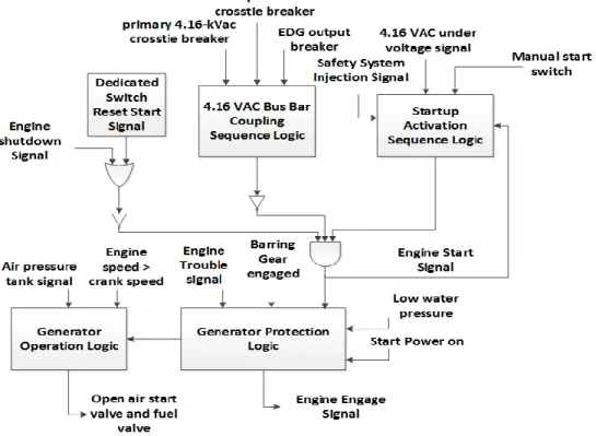
4.4.1 Emergency Diesel Generator Start Up Sequencer (EDGSS) ... 89
4.4.2 SymPLe: An FPGA overlay architecture ... 90
4.5 Design Assurance using Model Based Engineering (MBE) ... 92
4.5.1 Design Assurance Workflow ... 93
4.6 Implementation of Monitors Based on Synergy ... 104
4.7 Findings on Synergy from V&V of Model Based Designs ... 108
Chapter 5 ... 111
Design and Evaluation of Multilevel Runtime Monitoring using Model-based Engineering Methods ... 111
5.1 Introduction and Purpose ... 111
5.2 MathWorks Simulink Verification Blocks... 111
5.3 Specifying monitoring properties using Event Calculus ... 113
5.4 Example CPS: Anti-lock Braking System (ABS) ... 115
5.4.1 Rationale for monitor placement in the ABS ... 115
5.4.2 Monitoring properties for ABS controller expressed using Event Calculus ... 116
5.5 Evaluation of Multilevel Monitors ... 118
5.6 Discussion: Monitor Organization Patterns ... 126
5.7 Summary ... 130
Chapter 6 ... 131
ARM Processor Debug and Trace Capability to Assist Multilevel Runtime Monitoring ... 131
6.1 Introduction and Purpose ... 131
6.2 ARM Processor Family ... 132
6.3 ARM Coresight Architecture Components ... 134
6.3.1 ARM Trace Infrastructure ... 134
6.3.2 ARM Debug Infrastructure ... 143
8
6.4.1 Online monitoring ... 144
6.4.2 Offline Monitoring ... 145
6.4.3 Trace Decoders ... 146
6.5 Keil and openOCD ARM development tools ... 151
6.5.1 Keil Micro Vison ... 151
6.5.2 OpenOCD ... 152
6.6 Example of a Functional monitor using ITM trace ... 153
6.7 Example of ITM hardware trace decoding which can be used for Execution monitoring ... 156
6.8 Discussions and Summary ... 158
Chapter 7 ... 160
Realization of Multilevel Monitors on Hardware and use of ARM Coresight trace for Functional Monitoring ... 160
7.1 Introduction ... 160
7.2 CPS for Multilevel Monitoring: Autonomous Emergency Braking (AEB) controller ... 161
7.2.1 Simulation Scenario ... 161
7.2.2 Examples of threats in an AEB system ... 162
7.3 Formulating Properties to Monitor at Runtime ... 163
7.4 Faults/attacks and their detection by the monitoring conditions in Simulink ... 166
7.5 Hardware implementation of Runtime Monitors ... 168
7.5.1 Workflow for generation of monitors ... 168
7.5.2 Implementation of Monitors ... 169
7.5.3 Observations ... 172
7.6 Functional Monitoring using ARM Embedded Trace ... 176
7.7 Preliminary assessment of scalability of TeSSLa monitors and FIL system components ... 179
7.8 Summary ... 180
Chapter 8 ... 182
9
8.1 Key contributions of this dissertations ... 183
8.2 Future work ... 184
Appendix A ... 185
A 1. Model Based Testing and Coverage Analysis of SymPLe architecture ... 185
A 2. Simulink Design Verifier ... 186
A 3. Safety Standard Compliance checks ... 187
A 4. Model to Code Equivalence and Code Coverage Analysis ... 189
A 5. Formal Verification of Code ... 193
A 6. FPGA in Loop Implementation of SymPLe ... 196
A 7. Hardware Fault Injection ... 197
A 8. Software in Loop (SIL) ... 198
A 9. Processor in Loop (PIL) ... 199
10
List of Figures
Figure 1: Cyber Physical System ... 22
Figure 2: Runtime verification framework. ... 25
Figure 3: Overview of runtime verification ... 26
Figure 4: Phase I – Design: Synergy between Design and Runtime Verification Specifications ... 28
Figure 5: Phase II – Runtime: Synergy between Design and Runtime Verification Specifications……... 28
Figure 6: Multilevel monitoring of a CPS. ... 33
Figure 7: Workflow toward the realization of Multi-level runtime monitoring. ... 42
Figure 8: Three Universe Model . ... 46
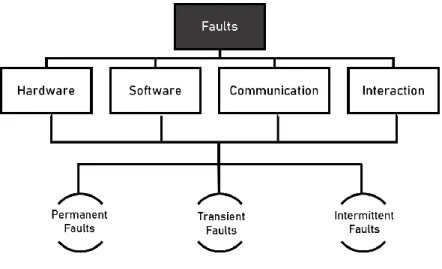
Figure 9: Classification of faults based in a CPS ... 48
Figure 10: Taxonomy of Attacks in CPS ... 50
Figure 11: Structure of a Cyber Physical System ... 51
Figure 12: Multilevel monitoring ... 55
Figure 13: Need for Attacks/Faults detected by monitors at multiple levels ... 55
Figure 14: Language based formal model for runtime monitors [69]. ... 62
Figure 15: Words w in the language of the computer-based system L(A) classified into Lio(A), Ln(A) and L(A) and are recognized by monitors Mio, Mn and Mrespectively. ... 64
Figure 16: In-situ Monitor ... 68
Figure 17: External Runtime Monitor ... 69
Figure 18: Monolithic Monitoring ... 70
Figure 19: Distributed Monitoring ... 71
Figure 20: Heterogeneous Monitoring ... 71
Figure 21: Stream of data indicating position and monitor indicating attack ... 73
Figure 22: Snippet of the TeSSLa specification. ... 73
Figure 23: TeSSLa Monitor output that verifies the property to ensure correct throttle action. ... 74
Figure 24: STPA hazard analysis and Model based V&V inform us on “what to monitor” at runtime and placement of monitors. ... 76
Figure 25: Conceptual view of STPA driven Runtime Monitor ... 78
Figure 26: Runtime monitor framework ... 81
Figure 27: Basic elements of a Model Based Engineering design. (inspired by [94]) ... 85
Figure 28: V&V workflow to explore synergy ... 87
Figure 29: High Level model of the Emergency Diesel Generator Startup Sequencer ... 90
11
Figure 31: V&V workflow ... 93
Figure 32: Simulink Test Sequence block and Test Assessment block ... 96
Figure 33: Model Based Testing detects Deadlock scenario ... 97
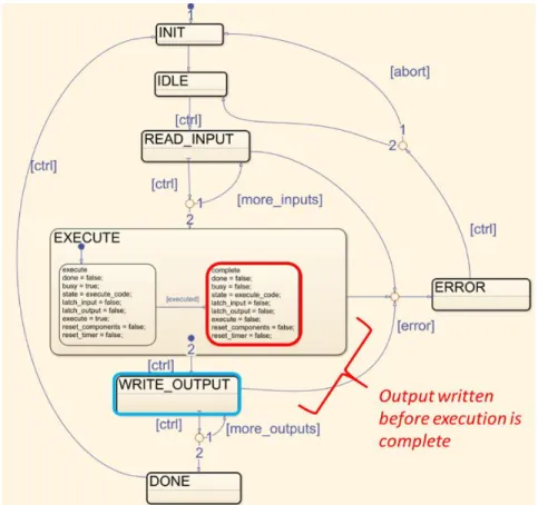
Figure 34: Transition to write_output state before execution is complete. ... 98
Figure 35: Bi-directional traceability between requirements, model and formal proofs ... 99
Figure 36: Simulink Design Verifier property ... 100
Figure 37: Design Verifier property to verify valid transition. ... 101
Figure 38: Counter-example showing invalid transition due to design issue in error handling ... 101
Figure 39: Fault Injection on Greater Than Functional Block in SymPLe architecture ... 102
Figure 40: Runtime monitor property modeled using Simulink verification blocks ... 103
Figure 41: EDGSS model verified using TeSSLa Runtime monitors ... 105
Figure 42 : Stuck-at "1" fault injected on EDGSS model and detected by the monitor... 106
Figure 43: Transient Faults injected on SymPLe and detected by the monitor ... 107
Figure 44: Iterative workflow shows synergy between Design verification and runtime monitors ... 108
Figure 45: Model-based verification guides 'what to monitor' and 'where to monitor'. ... 110
Figure 46: Simulink temporal blocks, proof assumptions, assertion and Implies blocks ... 113
Figure 47: Implementation of a property using Simulink blocks. ... 115
Figure 48: Anti-lock Braking System. ... 116
Figure 49: Fault Saboteurs injected in the ABS. ... 119
Figure 50: No attack/fault on the CPS. ... 120
Figure 51: Property 1 modeled in Simulink, verified by the Functional Monitor M1 ... 121
Figure 52: Stuck at 0 fault on the ABS controller. ... 121
Figure 53: Property 3 modeled in Simulink, verified by the Network Monitor M3 ... 122
Figure 54: Bus traffic delay detected by Network monitor. ... 123
Figure 55: Property 2 modeled in Simulink, verified by the Data Monitor M2 ... 123
Figure 56: Attack on wheel speed sensor detected by monitor. ... 124
Figure 57: Attack detected by multiple monitors. ... 125
Figure 58: Parallel, Sequential, Associative and Complementary monitor organization. ... 126
Figure 59: ARM Coresight Architecture ... 134
Figure 60: ETM trace viewed on a Keil Micro Vision IDE ... 139
Figure 61: Design choices for execution monitoring that use ARM Coresight Debug and Trace. ... 144
Figure 62: An example OpenCSD decoded trace for an ETMv4 trace ... 149
Figure 63: Enabling debug and trace features in Cortex M processor using Keil IDE ... 152
12
Figure 65: Sending ITM traces from ARM Processor via the SWO to the monitor ... 153
Figure 66: TeSSLa specification to check for change in x ... 154
Figure 67: (a) Input trace for variable x (b) TeSSLa monitor output to detect change in x ... 155
Figure 68: TeSSLa monitor output on the FPGA ... 155
Figure 69: PC sample decoded on the FPGA. ... 156
Figure 70: Offline decoded ITM PC sampling data in Cortex M devices ... 157
Figure 71: Profiling information ... 158
Figure 72: AEB system. ... 162
Figure 73: Workflow for generation of TeSSLa monitors and integrating with Simulink model ... 169
Figure 74: Schematic showing the AEB controller, plant, and sensors ... 170
Figure 75: No fault/attack in the AEB system. ... 173
Figure 76: Data monitor ... 174
Figure 77: Functional monitor. ... 175
Figure 78: Network monitor ... 176
Figure 79: AEB controller implemented on an ARM Cortex M4 processor and verified by TeSSLa monitors on the FPGA. Plant and sensors are simulated on the Simulink model. ... 177
Figure 80: TeSSLa property that verifies the relationship between AEB_status and FCW active signal 178 Figure 81: TeSSLa input and output streams ... 178
Figure 82: TeSSLa monitor verifies an AEB property ... 179
Figure 83: Low coverage indicated in Simulink blocks. ... 185
Figure 84: Coverage Analysis of SymPLe component.. ... 186
Figure 85: General Proof Outline for Simulink Design Verifier . ... 187
Figure 86: Polyspace static verification report... 189
Figure 87: Modelsim Co-simulation Equivalence Testing ... 190
Figure 88: Modelsim Co-Simulation ... 190
Figure 89: Test Manager Modelsim Results and Modelsim Co-Simulation ... 191
Figure 90: Code Coverage Summary ... 192
Figure 91: Assertion Based Verification of HDL code to verify error handling ... 194
Figure 92: Mentor Questa Counter example when property fails. ... 195
Figure 93: Simulink DV Property Proving for a SymPLe AND functional block ... 196
Figure 94: Assertion Based Formal Verification performed Using Mentor Questa tool ... 196
Figure 95: FPGA in Loop implementation of EDGSS application ... 197
Figure 96: Software in Loop Simulation ... 198
13
List of Tables
Table 1: Attacks/faults injected on the CPS. ... 119 Table 2: Snippet of STPA analysis of UCAs in AEB ... 164 Table 3: Fault/attack injection in AEB system and detection by multilevel monitors. “Y” indicates
fault/attack detected and “N” indicates fault/attack not detected. ... 167 Table 4: Resource utilization of multilevel monitors ... 180
14
Publications
Published/Accepted
1. Gautham S., Jayakumar A.V., Elks C. (2020) Multilevel Runtime Security and Safety Monitoring for Cyber Physical Systems Using Model-Based Engineering. SAFECOMP 2020 Workshops. SAFECOMP 2020. Lecture Notes in Computer Science, vol 12235. Springer, Cham.
https://doi.org/10.1007/978-3-030-55583-2_14 Tier 1
2. Gautham, S., Bakirtzis, G., Leccadito, M.T., Klenke, R.H., Elks, C.R., 2019. A multilevel cybersecurity and safety monitor for embedded cyber-physical systems: WIP abstract, in: Proceedings of the 10th ACM/IEEE International Conference on Cyber-Physical Systems. Presented at the ICCPS ’19: ACM/IEEE 10th International Conference on Cyber-Physical Systems, ACM, Montreal Quebec Canada, pp. 320–321.
https://doi-org.proxy.library.vcu.edu/10.1145/3302509.3313321
3. Weiss, A., Gautham, S., Varma Jayakumar, A., Elks, C., Kuhn, D.R., Kacker, R.N., Preusser, T.B., 2020. Understanding and Fixing Complex Faults in Embedded Systems. IEEE Computer Magazine. (Accepted). Impact factor 3.56
4. Jayakumar, A.V., Gautham, S., Kuhn, R., Simons, B., Collins, A., Dirsch, T., Kacker, R., Elks, C., 2020. Systematic Software Testing of Critical Embedded Digital Devices in Nuclear Power Applications, accepted to be published in IEEE International Symposium on Software Reliability Engineering (ISSRE). Tier 1.
5. Elks, C. R., Bakker, T., Hite, R., Gautham, S., Venkatesh, V., & Moore, J. (2017, June). SymPLe 1131: A novel architecture solution for the realization of verifiable digital I&C systems and embedded digital devices. In 10th Int. Topical Meeting on Nuclear Plant Instrumentation, Control, and Human Machine Interface Technologies, San Francisco, California.
To be Submitted/Under Review
1. Gautham, S., Rajagopala, A., Deloglos,C, Elks, C.,“Realizing Multilevel Runtime Monitoring for Detection of Hazards in Cyber Physical Systems” Proceedings of the 12th ACM/IEEE International Conference on Cyber-Physical Systems. Presented at the ICCPS ’21 (under review). Tier 1.
2. S. Gautham, A. B. Rajagopala, A. Weiss and C. Elks " Survey of safety and security monitors using ARM Embedded Trace" (to be submitted)
3. Smitha Gautham, Athira Varma Jayakumar, Richard Hite, Christopher Deloglos, Jason Moore, Ashraf Tantawy, Matt Gibson, Carl Elks, “On the Application of Model Based Design and Assurance Methods to Nuclear Power Safety Critical Instrumentation and Control Systems” IEEE Transactions on Nuclear Science. (to be submitted)
4. S. Gautham, A. V. Jayakumar, A. B. Rajagopala, R. Hite, and C. R. Elks, “Finding Synergy Between Design-Time Assurance and Runtime Verification by Means of Model-Based Engineering,” (to be submitted)
5. Co-author: The SymPLe architecture concept: Achieving Verifiable and High Integrity Instrumentation and Control Systems through Complexity Awareness and Constrained Design, International Conference on Dependable Systems and Networks. Tier 1.
15
Published Sponsored Research Reports
• Major contributor and Co-Author - Achieving Verifiable and High Integrity Instrumentation and Control Systems through Complexity Awareness and Constrained Design. No. 15-8044. Electric Power Research Institute (EPRI), 2019. DOI: 10.2172/1547345
• Major contributor and Co-author “Realizing Verifiable I&C and Embedded Digital Devices for Nuclear Power. Second Annual Technical Report.” Dept. of Energy ASI NEET-2, 2017
• Minor contributor and Co-author “Realization of an Automated T Way Combinatorial Software Testing Approach for a Safety Critical Embedded Digital Device” US department of Energy Idaho National Labs Technical Report, INL/EXT-19-54096, June 2019. DOI: 10.2172/1606019
• Minor contributor and Co-author “Specification of a Bounded Exhaustive Testing Study for a Software-based Embedded Digital Device. ”US department of Energy Idaho National Labs Technical Report, INL/EXT-18-54045, November 2018
16
List of Abbreviations
CPS Cyber Physical Systems
RV Runtime Verification
MBD Model Based Design
MBDE Model Based Design Engineering FPGA Field Programmable Gate Array DepDevOps Design Development Operation V&V Verification & Validation
STPA Systems Theoretic Process Analysis FTA Fault Tree Analysis
FMEA Failure Mode and Effects Analysis RTL Register Transfer Level
HDL Hardware Description Language
VHDL Very High-Speed Integrated Circuit Hardware Description Language IC Integrated Circuit
IEC International Electrotechnical Commission
FIL FPGA-In-Loop
MIL Model-In-Loop
SIL Software-In-Loop
EC Event Calculus
I2C Inter-Integrated Circuit SPI Serial Peripheral Interface
UART Universal asynchronous receiver-transmitter CAN Controller Area Network
DoS Denial of Service
I&C Instrumentation & Control PID Proportional Integral Derivative SIL Safety Integrity Level
ECU Electronic control unit ABS Anti-lock Braking System AEB Autonomous Emergency Braking SUO System Under Observation STL Signal Temporal Logic
17 MTL Metric Temporal Logic
LTL Linear-time Temporal Logic SRV Stream Based Runtime Verification PHA Preliminary Hazard Analysis
STAMP System-Theoretic Accident Model and Processes HAZOP Hazard and Operability Analysis
UCA Unsafe Control Action
EDGSS Emergency Diesel Generator Startup Sequencer
LS Local Sequencer
GS Global Sequencer
FB Function Block
DV Design Verifier
ISO International Organization for Standardization FI Fault Injection
MC/DC Modified Condition / Decision Coverage FBD Function Block Diagram
ABV Assertion Based Verification
ASIC Application-Specific Integrated Circuit MBT Model Based Testing
NPP Nuclear Power Plant
ID Identifier
NaN Not a Number
ETM Embedded Trace Macrocell PTM Program Trace Macrocell ITM Instrumentation Trace Macrocell STM System Trace Macrocell
DWT Data Watchpoint and Trace ELA Embedded Logic Analyzer SWO Serial Wire Output
SWD Serial Wire Debug SWV Serial Wire Viewer TPIU Trace Port Interface Unit
PC Program Counter
18 PFT Program Flow Trace
TMC Trace Memory Controllers ETB Embedded Trace Buffer
ETF Embedded Trace FIFO
ETR Embedded Trace Router ETS Embedded Trace Streamer FIFO First In First Out
DAP Debug Access Port JTAG Joint Test Action Group TDI Test Data In
TDO Test Data Out
TCLK Test Clock TMS Test Mode Select
CLK Clock
SWCLK Serial Wire Clock SWDIO Serial Wire Input Output
IO Input Output
CTI Cross Trigger Interface CTM Cross Trigger Matrix UAS Unmanned Aerial System
CAPEC Common Attack Pattern Enumeration and Classification CWE Common Weakness Enumeration
CVE Common Vulnerabilities and Exposures HW Hardware
19
Abstract
Multilevel Runtime Verification for Safety and Security Critical
Cyber Physical Systems from a Model Based Engineering
Perspective
By Smitha Gautham
A thesis submitted in partial fulfillment of the requirements for the degree of Doctor of
Philosophy in Engineering with a concentration in Electrical and Computer Engineering
at Virginia Commonwealth University
Major Director: Dr. Carl R Elks
Associate Professor, Department of Electrical and Computer Engineering
Advanced embedded system technology is one of the key driving forces behind the rapid growth of Cyber-Physical System (CPS) applications. CPS consists of multiple coordinating and cooperating components, which are often software-intensive and interact with each other to achieve unprecedented tasks. Such highly integrated CPSs have complex interaction failures, attack surfaces, and attack vectors that we have to protect and secure against. This dissertation advances the state-of-the-art by developing a multilevel runtime monitoring approach for safety and security critical CPSs where there are monitors at each level of processing and integration. Given that computation and data processing vulnerabilities may exist at multiple levels in an embedded CPS, it follows that solutions present at the levels where the faults or vulnerabilities originate are beneficial in timely detection of anomalies.
Further, increasing functional and architectural complexity of critical CPSs have significant safety and security operational implications. These challenges are leading to a need for new methods where there is a
20
continuum between design time assurance and runtime or operational assurance. Towards this end, this dissertation explores Model Based Engineering methods by which design assurance can be carried forward to the runtime domain, creating a shared responsibility for reducing the overall risk associated with the system at operation. Therefore, a synergistic combination of Verification & Validation at design time and runtime monitoring at multiple levels is beneficial in assuring safety and security of critical CPS. Furthermore, we realize our multilevel runtime monitor framework on hardware using a stream-based runtime verification language.
21
Chapter 1
Introduction
This dissertation advances the state-of-the-art in the development of Multi-level Runtime Monitoring for safety and security critical Cyber Physical Systems. This chapter describes the motivation of this dissertation research, which is the difficulty in ensuring safety and security in Cyber Physical Systems along the design, development and operational context continuum.
1.1 Background
As today’s embedded systems become ubiquitous, we as a society are relying on their functionality more and more to perform tasks that were once labor intensive, costly, tedious, or even unattainable without the benefit of low-cost embedded computer hardware and software technology. The end result of this technology ascendance is a predominance of advanced embedded system devices that have transformed the way we interact with the world we live in. Examples of such transformative technologies are Edge Computing, Cyber Physical Systems, and Fog Computing, to name a few.
Low cost advanced embedded system and high-performance network (wired and wireless) technology are among the key driving forces behind the rapid growth of Cyber-Physical System (CPS) applications. Therefore, we are observing the rapid uptake of Cyber-Physical Systems across a number of domains, with a potential economic impact of as much as $11.1 trillion per year globally by 2025, in different settings, including connected semi-autonomous vehicles, healthcare, energy, manufacturing, smart homes, and smart cities [1].
CPSs are comprised of multiple coordinating and cooperating components, which are often software intensive, interacting with each other and with the physical world around us. Figure 1 shows an overview of such a CPS.
22
Figure 1: Cyber Physical System comprising of multiple physical devices, computational elements and network (inspired by [2]).
Cyber Physical Systems are used in a number of safety critical applications and their complexity and functionality are on the rise in such applications. Applications such as robotics, autonomous systems, tele-medicine and avionics are examples of CPSs becoming more complex, incorporating new technology and with varied features. For example, a CPS such as a modern automobile has environmental and engine control systems, sensors of all types, navigation systems, cameras all working together to achieve enhanced driving experiences and safety [3]. With the emergence of autonomous vehicle operations, the sphere of control with respect to vehicle is increased to include awareness and sensing of other traffic. As such, the functional and structural complexity of these systems are rapidly increasing, which can have significant engineering and operational impacts. Specifically, verifying and validating highly complex systems is a known difficult problem with real world cost impacts [4]. With the exponential growth of CPS and their application not only in domestic field but also in critical applications such as avionics, nuclear plants, smart grids etc., security of the CPS is also of paramount concern. Secondly, if the safety or integrity of a CPS is a significant factor (example, energy distribution smart grid) then failure or malicious exploitation of such complex CPSs can result in far-reaching consequences to human life, environment, and financial loss. Therefore, there is a need to ensure safety and security in increasingly sophisticated CPSs.
1.2 Motivation: Example Incidents and Problems
The design of highly-reliable and safety critical systems is driven by the functionality it must deliver while maintaining safety in the presence of faults. Recent incident and accident reports from various
23
sectors show that even when systems are designed and developed and certified to very high standards (e.g. IEC 61508 SIL4, DO-254, DO-178b), problems can occur that defeat the fault tolerance or cyber security defenses of the said systems. Ref [5] examined the role of software in five aircraft incidents or adverse effects and concluded that in “spite of rigorous design methodologies and reviews, the combination of complexity and unexpected failure mode defeated systemic fault tolerance”. Ref [5] identified the critical role of flawed sensor inputs as a key determinant or trigger of “dormant” software defects in recent adverse events. Ref [5] also concluded that in some cases the software was complying with its functional requirements but still placed the aircraft in a hazardous state or contributed to an adverse event.
Ref [6] examined the occurrence of byzantine failures in aerospace systems and concluded that the occurrence of these types of insidious faults probably happen much more frequently than previously suspected. Ref [6] presents evidence of byzantine fault behavior in three different flight control systems and shows the circumstances of byzantine failure manifestation. Ref [7] discovered a byzantine failure in the Draper Labs Fault Tolerant Processor (FTP) which resulted in the quad FTP computer diverging into a “pair-wise” split voting pattern which would have been catastrophic if it had occurred in-flight.
Ref [8] reviewed fifteen catastrophic accidents, and evaluated the causative roles that software played in the accidents. Ref [8] noted that quite often the causes were a combination of software failures triggered by hardware failures and human error compounding the response. Finally, the recent Boeing 737 max Maneuvering Characteristics Augmentation System (MCAS) incidents and accidents only further establish the evidence that complex hazard scenarios and pilot interactions arising from the flawed control system software are challenging to detect during design and testing. As noted in the October 2019 National Transportation Safety Board (NTSB) report; “pilots’ responses to unintended MCAS operation were not consistent with the underlying assumptions about pilot recognition and response that were used for flight control system functional hazard assessments…” the report further noted that MCAS started out as a modest software system and then evolved to a complex system without full understanding of the complexity and the system dependencies with respect to MCAS [9].
What these examples and survey analysis papers suggest is that even though a system has been thoroughly tested and verified during the design process, expected behavior of the system is difficult to guarantee during unusual off-nominal situations [10]. With the evolution of technology and emergence of critical autonomous systems and Machine Learning, systems today can self-learn and adapt their behavior based on the external environment. This can pose new challenges to Verification and Validation (V&V)
24
assurance performed at design time and necessitates a means of ensuring that the system requirements and design assurance are carried further down to the implementation stages. We assert that this need may be fulfilled by having runtime monitors that observe system behavior and provide assurance of safety and security without interfering with the system under observation [11]. Therefore, using both comprehensive design assurance methods and run time verification may be beneficial to achieve higher levels of safety and security of the system.
1.3 Runtime Verification for CPS
Runtime Verification (RV) is one of the promising techniques for immediate detection of infected states and hazards. It is a mature engineering domain with a vast literature base that has been successfully used in various safety critical industries [12] [13, p. 2] [14]. As stated in [15], runtime verification can be defined as:
“Runtime verification is the discipline of computer science/engineering that deals with the study, development, and application of those verification techniques that allow checking whether a run of a system under scrutiny satisfies or violates a given correctness property.”
Runtime verification sits in between traditional dynamic testing methods and formal exhaustive proof techniques (theorem proving). It is typically classified as a lightweight formal verification method. Classical verification techniques such as model checking, dynamic and static testing are employed to provide design assurance. This is complemented by formal, lightweight runtime verification methods. Unlike a formal proof, runtime verification is not complete or exhaustive, but it provides more guarantees of correctness than dynamic testing.
Runtime verification is often referred to as runtime monitoring, trace analysis etc. Checking a system for correctness of a property is referred to as verification, while monitoring only implies observation of the behavior of a system [16]. In this dissertation, the term monitoring is used for both observation and correctness checking. Therefore, runtime verification and runtime monitoring are used synonymously.
At very broad stance, the monitor observes the execution behavior of a target system during runtime while making as few as possible assumptions about the trustworthiness or proper functioning of the monitored system [10] [16] [15] [17]. Referring to Figure 2, a monitor is concerned with the detection of violations (or satisfactions) of properties (e.g. safety, security, functional, timeliness etc.) by analyzing the
25
trace of a system [18]. A trace is comprised of observed variables, memory patterns, an execution control and data flow, protocol sequences, etc. When a violation is observed by a runtime monitor, it typically does not influence or change the program’s execution. Hence, it does not repair the observed violation but forms the basis for mitigation of observed problems.
Figure 2: Runtime verification framework (inspired by [19]).
To decide on correctness, a monitor needs a reference of acceptable or correct behavior to compare the extracted trace information with. This “reference of acceptable behavior” is often derived from the natural language requirements of the system and then translated into temporal logic formulas– a type of logic that allows reasoning over sequences and time (as seen in Figure 2). The temporal logic formulas reside in the monitor. Execution trace information (i.e. states function variables, decision predicates, etc.) is extracted directly from the target system and forwarded to the monitor where temporal logic expressions are elaborated with the trace data for an on-the-fly validation of system behavior. For example, we can monitor discrete representations of continuous time variables such as sensor readings, system states, and application level variables. In such cases, the monitor uses traces of a set of information states from the CPS to check if the system is compliant with the “reference of acceptable behavior” (e.g. a safety property or checking assertion). Acceptable behavior implies there are checking conditions or detection predicates to determine if the system is demonstrating acceptable behavior. These checking conditions are called specifications which can sometimes be synthesized on a hardware platform as seen in Figure 3.
26
Figure 3: Overview of runtime verification.
1.4 Integration of Design and Operational Phases to achieve
Dependability: DepDevOps
While subsections 1.2 and 1.3 discussed the need to augment design time verification with runtime monitoring, this subsection emphasizes the synergy between them. Design time verification helps provide an understanding of the system, which in turn helps develop the properties to be monitored at runtime. So, without design time verification, we would not have a clear understanding of what to monitor. On the other hand, many assumptions made at design time may not hold true at run time making assurances based on only design time verification weak. This motivates the need to view design time and runtime synergistically.
This is particularly important as CPSs are evolving towards software intensive systems where functionality, integration, and operations of a given system are largely governed by its complex software interactions. Although software testing methods and practices have undergone tremendous progress over the past 20 years, the evolving nature of software intensive CPSs can create layers of unforeseen failure modes and complex attack surfaces. As we have seen in recent years, design assurance and certification methods may not be sufficient to uncover all design flaws or scenarios that lead to hazardous operation. This is most evident in the Boeing 737-max incidents where the loss of airspeed sensors resulted in unexpected and unanticipated vehicle flight behavior [2]. Such challenges (among others) are emerging drivers for new methods where there is a continuum between design time assurance and runtime or operational assurance. That is, design assurance cannot stand on its own and needs safety and security to be carried forward to the runtime domain creating a shared responsibility for reducing the overall risk associated with the system at operation. On the other hand, runtime verification needs the knowledge gained from design assurance methods to formulate critical properties we want to monitor at runtime. This is the basis of a “reference of acceptable behavior” for a monitor. These new methods are
27
sometimes referred to as Dependable Development Operations Continuum (DepDevOps) [20], [21]. The DevOps continuum strives to bridge the gap between the design and operational phases, reduce cost without compromising safety.
1.4.1 A Conceptual View of Integrating Design Development and Runtime
Verification for CPS
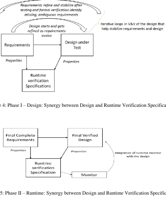
The development process typically begins by formulating the design based on an initial set of requirements. The design is then verified by testing and formal property proving at the unit level, integration level and system level. During the course of verification and design development, we find missing or unclear requirements which get redefined as the design stabilizes during this first phase. This iterative process, as shown in
Figure 4, ensures that we have a complete set of finalized requirements and a verified design. Runtime monitoring properties are derived from these finalized requirements. The iterative process of finalizing requirements and the design is important to ensure that all the critical safety and security properties are captured by the monitor specifications. Further, employing systematic hazard analysis methods such as System Theoretic Process Analysis (STPA) and Hazard and Consequence Analysis (HAZCAD), help analyze the failure modes in a design and refine the requirements to include design considerations to avoid hazards or loss scenarios. Loss scenarios are failures in a system that that can lead to loss of life and property.
The finalized requirements encompass the knowledge gained from each verification step and inform us on critical elements and interactions in a system, which when failed, could lead to a hazard. This knowledge gained during the verification stages help us formulate informed runtime monitor specifications.
In phase II, the runtime monitor is seamlessly integrated with the design. This integration allows us to determine the efficacy of the monitors in detection of anomalies in the CPS for which they were designed. Fault injection campaigns and cyber-attack injection performed on a CPS model can violate a safety property of a system. This violation should be detected by the runtime monitor.
A key contribution of this thesis is the synergetic combination of phase I and phase II which provide tighter integration of design and operational phases of a system. We explore this synergy from a Model-Based Engineering (MBE) perspective.
28
Figure 4: Phase I – Design: Synergy between Design and Runtime Verification Specifications.
Figure 5: Phase II – Runtime: Synergy between Design and Runtime Verification Specifications.
1.5 Critical Issues
1.5.1 Observation of target system
The key precondition for this runtime verification approach is the observability of the system operation such as system states, data and control flow information etc. necessary to access the behavior of the
29
system at runtime, at time intervals of interest. The observability can be related to physical variables or computed states of a system as explained below:
1. An important challenge to runtime monitoring is observability of the value of a physical quantity of the system or its environment that a monitor needs, in order to be able to verify a correctness property for a comprehensive set of scenarios. For example, we can have a simple property “the maximum acceleration of a vehicle should be less than aMAX m/s2”, which we can verify with data from an accelerometer (directly) or a vehicle velocity sensor (by differentiating velocity). However, while going up a steep hill or incline, the vehicle should not be able to accelerate as much, let us say acceleration should not be more than 0.5aMAX. We cannot change the property to 0.5aMAX, as on a level road it will produce a false positive. However, if we stick to aMAX this monitor could produce a false negative as an acceleration of say 0.8aMAX would not cause the property to be falsified even though such a high acceleration is impossible on a steep hill or incline.
Therefore, to have a better monitoring condition, the maximum acceleration of the vehicle should be a made a function of the incline of the road. However, if the vehicle does not have a level sensor this quantity is not observable. Unless this level sensor is physically incorporated in the car, we cannot refine the monitoring property due to lack of observability and are confined to a property which does not completely account for all scenarios. This scenario also emphasizes that integrating such runtime considerations early, during the design phases help us identify deficiencies in the system that need to addressed while implementing runtime monitors.
2. Another observability issue deals with processors where internal variables should be extracted with minimal or no intrusion to the processor in order for a monitor to verify its functionality. For example, the controller of a complex chemical plant may have 5 inputs and 2 outputs that are observable and can be used to formulate a correctness property. But the evaluation of the output may be a complex function of the time history of these 5 inputs and involve calculation of 10 other internal variables/states that are not visible from outside this controller. However, this problem is in principle solvable, as the internal states can be obtained by software instrumentation with its known limitations, namely overly intrusiveness to program execution. A good monitor should be minimally intrusive to the running program, have low communication overhead, should not have any interference with the program behavior, and must be space efficient (no need to store vast amount of data) and time efficient (no exponential growth in time to form a decision).
30
1.5.2 Safety and Security – How to do both, if possible?
A CPS is often comprised of numerous integrated components and subsystems interacting and communicating with each other to satisfy system (plant) goals. These goals are often related to the functional performance, safety and security of the service a CPS is providing, for example, an automobile cruise control will always disengage when the brake is applied. With the functional safety applications, failure due to a cyberattack can lead to situations where the attack can enable a hazardous situation which could affect safety. Therefore, it is important for the runtime monitor to address both safety and security requirements of the system.
In the context of safety critical systems, Cyber Security can be viewed as an extension or expansion of the standard physical threat models (faults, failures) for ensuring system safety [22]. The types of cyber threats and exploits for cyber physical systems are well documented and surveyed in literature [23]. Nonetheless, assuring global safety and security together is a challenging problem as they may be in conflict with each other during certain conditions. For example, if a given security property detects that a cyber intrusion is present, it may mitigate this issue by blocking an input temporarily. In doing so, it may compromise the ability of the safety property to determine if the system is safe during the period of time the input is blocked. In this case, the system is secure but potentially unsafe. However, if we take the somewhat tapered viewpoint that deliberate cyber-attacks that violate safety conditions are of primary concern, then RV provides coverage of security in a limited sense. Moreover, the temporary blocking of input discussed above, is due to the mitigation strategy adopted to counter this attack and not a problem with the monitoring scheme. As such, this dissertation is focused on runtime monitoring for detection of safety and security violations and mitigation strategies are beyond the scope of our work.
Another issue is whether RV or monitoring can distinguish between attacks and faults. In fact, there are classes of cyber-attacks that are indistinguishable from physical faults from an external point of observation [24]. However, in these cases RV can provide timely trace information to offline diagnostics or forensics to determine if the system misbehavior was due to a fault or cyber event. The critical proposition moving forward is to investigate how RV can accommodate both security and safety checking.
31
1.5.3 The Specification of Safe and Secure – Where does it come from?
As discussed above the violations of a safety and security condition may have a common origin: design faults, physical faults, or cyber-attacks that change a combination of system states or variables which could lead to hazardous conditions and safety violations. Consider an autonomous car, where a sharp turn at high speeds can cause skidding or toppling. To assure safety of the car, there should be specific bounds for the steering wheel angle for a given speed of the car. More importantly, at design time such system requirements should be verified (either formally or by testing or both). Design time V&V can provide significant insight into not only what should be monitored, but also how it should be monitored. Nonetheless, most RV frameworks to date gloss over on how design time V&V informs the RV strategies. It is just assumed that high level safety and security requirements can be translated into monitorable properties and checking conditions, which is not realistic for CPSs. Based on our early work, we noted that there is an interplay between requirements, specifications and design that is rather non-intuitive [25]. High level requirements are often encoded in the design at the lower levels of abstraction (either as hardware or software). It is important to understand the decomposition high-level requirements in lower-level implementations of a design so that we have a complete system’s perspective while formulating runtime monitor properties.
Therefore, part of the dissertation is to derive the monitoring properties with System Theoretic Process Analysis (STPA), then investigate the use of Model-Based Design and Engineering (MBDE) to verify these monitor designs before finally implementing them on hardware. This enhances the effectiveness of monitorable specifications and makes them more comprehensive.
1.6 Need for Multilevel Monitoring of the Target System
Modern embedded digital devices have evolved to the point where all types of heterogeneous processing and data mobility reside within a single platform or chip from low-level onboard sensor pre-processors to dedicated network communication cores. The integration of customizable system on a chip technology and flexible communication enables tight integration with the physical world. For example, physical components such as sensors and actuators, embedded subsystems and the network to communicate among the components are tightly integrated. The CPS architected from this technology are increasingly vulnerable to design flaws, software flaws, and security threats at multiple levels that span both hardware and software implementations. These multiple levels of integration in such complex systems expose
32
attack surfaces and can potentially be susceptible to attack vectors. Given that computation and data processing vulnerabilities may exist at multiple levels in embedded CPS, it follows that solutions should be present at the levels where the faults or vulnerabilities originate. We assert that a viable approach to this problem is to employ runtime security and safety monitoring at these various levels of processing and integration. Such an approach is beneficial for timely detection of attacks (or failures) and lessen the burden of monitoring overhead. In this dissertation, we have three levels of monitoring as shown in Figure 6:
1) Sensor or Data level - The sensors and actuators constantly interact with the outside environment and the data monitor verifies the integrity of data coming from these devices. The data monitor may also verify configuration modes of the sensors to ensure they are consistent with the given application usage.
2) Computational level - The correct functionality of the computational elements, typically a controller, in a CPS is critical to avoid incorrect actions by the system leading to hazards. We then monitor the input-output relationship of a controller using a functional monitor. Additionally, some attacks may specifically alter the execution sequence of a program on the controller that can be detected by verifying the instruction traces using an execution monitor.
3) Communication Level - Sensors, actuators and computational units in a CPS use communication protocols such as UART, I2C and buses such as CAN. The flow of information, time delay, etc. can be monitored by a network monitor to detect faults/attacks on communication.
In this dissertation, we demonstrate the need for multilevel monitors for effective and comprehensive detection and isolation of attacks by performing data attack and fault injection on a CPS model.
33
Figure 6: Multilevel monitoring of a CPS.
1.7 Problem Statement
A key problem in CPS is that as systems become more complex, failures and exploits are more likely to occur despite rigorous design time Verification & Validation (V&V). The root causes of these failures are very often traced back to poorly understood interdependencies between computer control systems and physical structures or unknown or unfamiliar failure modes that result from the physical and computing relationships [26]. There is a need to ensure that the critical properties still hold true and are consistent at runtime. The gap between design time safety assurance and runtime behavior needs to be addressed. Due to increasing complexity of CPS, safety and security cannot be an afterthought, but has to be considered throughout the design development. The integration of design and runtime verification is critical to achieve this.
Most runtime monitoring frameworks for CPSs emphasize the “how to” aspects of realizing monitors in a CPS architecture. This means that methodologies are mostly focused on how to instrument a system, assuming the “what” to monitor is a given. A comprehensive methodology to determine critical aspects of a design to monitor at runtime needs to be determined.
34
Additionally, “where to monitor” and the context of the monitoring need to be addressed. Furthermore, monitoring solutions with minimum intrusiveness is necessary. Understanding and demonstrating the need for multilevel monitoring and use of non-intrusive monitoring methods is critical to achieve this. This dissertation attempts to answer the key challenges mentioned above.
1.8 Goal and Objectives
The overarching goal of this dissertation is to demonstrate that a synergistic combination of V&V at design time and runtime monitoring at multiple levels is beneficial in assuring safety of a system as well as ensure its security against vulnerabilities or attacks at multiple levels.
Towards this goal, we present a Model Based Design (MBD) approach using MathWorks Simulink tools to verify the CPS system by initially performing testing, static verification and formal verification before implementing it on the hardware system. Thereafter, a novel multilevel monitor architecture is used to verify critical conditions at run time. Runtime monitoring properties are derived based on hazard analysis on the system and design time verification. Such monitors observe the system behavior by analyzing streams of information coming from the target system with no or minimal intrusion with its working. Further, we implement the monitors on hardware and verify the efficacy of the monitors in detecting faults/attacks. This approach could potentially improve the safety and security of a CPS.
1.9 Contributions and Scope of this Research
This work uniquely combines the benefits of design verification and runtime monitors to ensure safety and security. Our contributions are:
• Investigating and characterizing the synergy between the V&V process at design time and creation of effective runtime verification monitors.
• Development and realization of runtime monitoring framework observing the operation of a target CPS at multiple levels.
• Hardware implementation of the monitors using a stream-based monitoring language. The scope of this work is in developing and demonstrating a methodology of combining design time V&V and runtime monitoring at multiple levels that can effectively provide protection to a CPS. This work helps bridge the gap between design time assurance and runtime behavior of the system.
35
1.10 Roadmap of Research
This dissertation starts with Chapter 1 that introduces the critical issues in runtime monitoring. It specifically makes a case for the need to synergistically combine design time V&V and runtime monitoring as well as benefits of monitors at multiple levels. Next, Chapter 2 provides a comprehensive literature review of design time V&V and runtime monitors to identify the gaps in this research.
Thereafter, Chapter 3 describes the development of the multilevel monitoring framework and various ways of monitor organization. This chapter presents a comprehensive workflow to design runtime monitors beginning with identifying critical properties to monitor at runtime, placement of monitors, formulating monitor specification and implementation of monitors. Practical consideration for implementing runtime monitors such as data observability, expressiveness of specification by the RV language and executable monitors are discussed. Other important concepts such as monitor completeness and monitor correctness are briefly presented.
Chapter 4 explores the synergy between design assurance and RV using Model based Engineering techniques. A detailed case study is presented of the verification of an Emergency Diesel generator Start Up Sequencer implemented on a Field Programmable Gate Array (FPGA) overlay architecture, where runtime monitoring properties are derived from each verification stage. Further the runtime monitor is implemented on a FPGA using a stream-based verification language. In summary, this chapter attempts to describe a methodology that can answer the “what” to monitor and “where” to monitor questions from a MBE perspective.
Chapter 5 demonstrates the need for multilevel monitoring in a CPS by injecting faults/attacks at multiple levels on a CPS model. It explains why having localized monitors is beneficial in timely detection of faults/attacks. It clearly shows that a single monitor cannot solve the in-time hazard detection problem. In summary, this chapter answers the “where” to monitor question.
Chapter 6 discusses the issues of observability and extraction of data for monitoring at runtime. It gives an in-depth discussion of the ARM Coresight debug and trace capability that can be used to extract data and instruction traces with minimum or no intrusion to the target CPS. It presents design choices while engineering runtime monitors that use the ARM trace capability, along with the challenges in using embedded trace. In summary, this chapter answers the “how” to monitor with minimum intrusiveness question.
36
Chapter 7 presents the concepts of STPA hazard analysis and how this help the design of monitoring properties. An Autonomous Emergency Braking (AEB) system is used to demonstrate the need for multilevel monitoring. Runtime monitors are initially implemented using Simulink library blocks. Further, monitors are implemented using a stream-based verification language called TeSSLa to verify the data, functional and network integrity of the AEB system. The TeSSLa runtime monitors are integrated into the design to ensure that they are able to detect any anomalies in the CPS for which they were designed. Use of ARM processors, coresight capability to extract data traces is explained. In summary, this chapter uses an AEB system to demonstrate the use of the solutions to “what, where and how to monitor” questions to develop a comprehensive runtime monitoring solution and implement the monitors on hardware.
Finally, Chapter 8 summarizes and draws a conclusion of the work performed in this dissertation regarding synergetic use of design and runtime verification, multilevel monitoring, use of ARM coresight trace capability to achieve safety and security of a CPS.
37
Chapter 2
Related Work
The verification and validation of a design is critical in identifying design flaws and other safety issues in a CPS. However, there is no guarantee that a fully verified system will function as expected at runtime. Therefore, runtime monitors are especially employed in safety systems, during the operation phase, to complement the V&V efforts performed during design development.
On the other hand, it is not possible to verify every property at runtime. Hence, it is valuable to use design time V&V to understand the CPS vulnerabilities, that guide us to formulate appropriate runtime monitoring conditions. There are a number of challenges and design considerations while engineering a runtime monitor. These are illustrated in the surveys [27], [11] and [3]. Research on how design-time assurance can be carried to runtime is one of the important research areas pointed by the survey [28].
Therefore, a wholistic view of design time and runtime monitoring is required and the two need to work synergistically. However, such an approach is largely unexplored with the exception of a few instances in [29] [19] where this issue has been touched upon.
This dissertation proposes to address this gap by comprehensively studying the combination of design time V&V and runtime verification. Towards this end, the literature review in this section summarizes some of the key work in design time V&V and runtime monitors. Further, we review literature that use runtime monitors in CPSs to ensure safety and security.
2.1 Verification and Validation(V&V) of Design
Assurance in design is achieved by comprehensive Verification and Validation methods. As, systems are becoming more complex, traditional design assurance methods with manual coding are becoming difficult. Safety critical industries such as avionics, automobiles and nuclear industry have stringent requirements that the design should comply with standards such as IEC 61508, DO 254, DO 178, ISO 26262. Bidirectional traceability between requirements, design, test cases and formal proofs are some of the many requirements for compliance to these standards. In order to meet these stringent design
38
challenges, V&V and regulatory requirements of safety critical systems, Model Based Engineering (MBE) is widely used. MBE is used for the design and verification of both non-safety and safety critical systems in aerospace, power and automotive sectors [30] [31] [32]. Research on model-based V&V is presented in [33] [34] [35]. Ref [33] presents a verification workflow to designing and verifying medical device software along with the artifacts created in the process to support certification. Ref [36] reports how MBE tools can be used in the aviation industry and recommend areas where the certification guidelines can be improved to reduce failures. In addition, [37] discusses the benefits of V&V technology on avionics systems in reducing development costs and time.
These references indicate the use of MBE in design and verification of safety critical systems in various application domains. Additionally, the structural verification activities using MBE tools serves as an ideal platform to explore synergy between design time and runtime verification. Therefore, we use MBE extensively in this dissertation.
2.2 Synergy between design and runtime verification
In this dissertation, we explore how V&V activities in a MBDE environment can help us formulate effective runtime monitoring properties that cover critical design elements in a system. We also explore hazard analysis methods to identify monitoring properties.
2.2.1 Design Verification guides runtime monitor design
Ref [3] discusses the importance of considering security parameters in the design phase of a CPS. They explore the challenges in implementing security in CPS and the importance of runtime security monitoring considerations during design development. Ref [38] discusses the benefits in collaboration of design time and runtime verification to increase security in embedded systems. They discuss how the security constraints considered at design time can be monitored at runtime. Combining design time testing and runtime monitors is explained in Ref [39] with the example of an Advanced Driver Assistance System (ADAS). The test cases formulated at design-time are used again at runtime to verify the system by the runtime monitor to ensure that the system is within its safe behavioral requirements. Design time and runtime considerations to ensure safety and security in CPSs and Internet of Things (IOT) is discussed in [40]. Tool support to perform both testing and runtime verification is discussed in Ref [41].
![Figure 1: Cyber Physical System comprising of multiple physical devices, computational elements and network (inspired by [2])](https://thumb-us.123doks.com/thumbv2/123dok_us/1994514.2796294/23.918.167.742.109.364/figure-physical-comprising-multiple-physical-computational-elements-inspired.webp)


![Figure 33: Model Based Testing detects complex interactions that result in Deadlock scenario (based on [91])](https://thumb-us.123doks.com/thumbv2/123dok_us/1994514.2796294/98.918.217.699.284.571/figure-model-testing-detects-complex-interactions-deadlock-scenario.webp)