Experimental setup for unbalance fault detection and
vibration analysis in a cardan shaft (Part B)
Bernard Xavier Tchomeni1, Alfayo Anyika Alugongo2, Leonard Masu3
Vaal University of Technology, Mechanical Engineering Department, Vanderbijlpark, South Africa
1Corresponding author
E-mail:1bernardt@vut.ac.za, 2alfayoa@vut.ac.za, 3leonard@vut.ac.za Received 1 July 2019; accepted 23 July 2019
DOI https://doi.org/10.21595/vp.2019.20887
Copyright © 2019 Bernard Xavier Tchomeni, et al. This is an open access article distributed under the Creative Commons Attribution License, which permits unrestricted use, distribution, and reproduction in any medium, provided the original work is properly cited.
Abstract. This paper experiments a vibration measurement on a twin-rotor connected by a
Hooke’s joints. An experimental set-up for vibration analysis and unbalance fault detection in rotating machinery has been conducted to reveal the unbalance effect in signal transmission of the interconnected shaft through Hooke’s joint. Vibrations signals were measured and analysed using the Fast Fourier Transform (FFT), orbit patterns and time displacement of each rotor centre, to extract the signature of the unbalance fault. The results indicate the accuracy of the discussed approach for the twin-rotor unbalances diagnosis in an interconnected shafts system through a Hooke’s joint.
Keywords: rotor kit 4, Cardan shaft, rotor unbalance, FFT, rotor machinery, Hooke’s joint.
1.Introduction
Rotor balancing is required on all types of rotating machinery to ensure smooth machine operation [1]. A perfectly balanced shaft is not easy to achieve, even under normal operating conditions. Rotor balancing involves the whole rotor structure which consists of a large number of parts, including the shaft, discs, rotor-bearings and motor. Unbalance system is inherent in all machines and is one of the main causes of vibration. It is caused by an unequal distribution of mass in a rotating shaft and distinguished by a sinusoidal vibration of once per revolution. The major challenge in the area of vibration condition monitoring is the extraction and identification of the features that are characteristic of a fault before it becomes critical. Hence, the entire rotating machinery needs to be monitored incessantly for the faults diagnostics.
In simple rotating machinery (Jeffcott rotor), irregular distribution of masses in a rotating member is the cause of unbalance which, leads to centrifugal forces in the radial direction [2]. There are many disadvantages to a coupled unbalanced shaft system. When a system is rotating under the influence of the unbalanced mass, there is a huge possibility that undesired vibration occurs, which further may result into dysfunctions such as misalignment, unwanted noise, excessive stress in machine elements and also a high bearing thrust. This reduces the reliability of rotating parts and may cause premature failure in the bearing system [3].
Previously, interconnected twin shaft unbalance conditions was diagnosed mainly by performing a numerical analysis using FFT and orbit presentation. This paper focuses on the influence of unbalance on a twin misaligned shaft using vibration characteristics based on an experimental setup. The experimental setup system consists of an elastic Cardan shaft subsystems with a Hooke’s joint used to analyse the static balance problem. The obtained results will be correlated with the previous numerical analysis performed on the same interconnected twin-rotor model (Part A).
2.Unbalance as a mechanical fault
The static unbalance is the most common source of vibration in rotating machinery. It is a very important parameter, and it must be considered carefully in the design of modern machines, especially for machines requiring high reliability and operating at high speeds [2]. Mathematically,
the centrifugal force unbalance that causes undesired vibration is expressed as follows:
𝐹⃗ = 𝑚 𝜔 𝑟⃗ 𝑁 , (1)
where 𝑚 is the unbalanced mass (kg), 𝑟 is the radial coordinate of unbalanced mass from the center axis (𝑚 ) and 𝜔 is the angular speed in radians per second (rad/s).
3.Experimental approach
The test bench set up for the study of the power transmission between two shafts through the Hooke’s joint aims at the measurement of the natural frequencies and the determination of parameters making it possible to establish a comparative analysis with the adopted numerical approach.
3.1.Description of the experimental setup
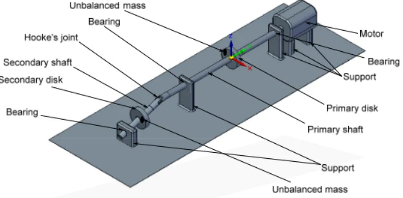
In order to analyse the behaviour of an unbalanced rotor, the test rig presented in Fig. 1 was designed and used for the analysis of the unbalance on twin-rotor. The experimental device consists of a frame, a drive system, and the rotors which comprise each of a lumped mass disc. The driven shaft is supported by two self-aligning bearings; the assembly is mounted on a concrete base and isolated from the environment by layers of elastomeric material which also serve as vibration absorbers. The experimental device allows the highlighting of vibratory phenomena namely the unbalance and noise excitations. The Solidworks software was used to build the prototype of the test bench model as shown in Fig. 1.
Fig. 1. Prototype of the experimental setup
3.2.Experimental procedure
The experiment was conducted on a modified Rotor Kit 4 Bently Nevada [3] (Fig. 2), the rig is constituted of a phase induction motor speed control connected to the driver shaft by a flexible coupling element. This system also includes a set of data acquisition interface unit controlled by Ascent Vb7 that controls the operation of the tachometer, computes and displays the operational deflection shapes of the measured structures. The system also comprises (1) Six proximity probes mounted at 90° right next to each shaft (in blue in Fig. 2). These proximity probes were connected to a transducer unit powered by a DC power supply. (2) A proximity probe tachometer is located next to the coupling to measure the motor spin speed. (3) Two identical discs of 90 mm diameter and 12 mm thickness, into which holes were punched for holding the unbalanced mass; (4) Two identical shaft measuring 10 mm in diameter and 750 mm in length. The electric motor can reach
to the first natural bending frequency of the rotor in order to avoid any irreversible deformation. To get the baseline result, the experiments were first performed with both balanced discs with at a maximum Hooke’s angle of 6°. Static balancing was performed at approximately 10 Hz (617 rpm-near the first critical speed). Further, the required unbalance was then considered into the rotor system by adding in both rotor shafts a trial mass of 34 gram on the discs, as explained in the previous section. Experimental studies through a series of tests were therefore performed to focus on the relevant information in the orbit patterns, time-displacement and FFT spectrum and to discriminate the unbalance fault component.
Fig. 2. Experimental setup
3.3.Experimental validation of numerical models
The purpose of the test bench set up for the study is to measure the spectral frequencies and to determine parameters for establishing a comparative analysis of a balance response (during run-up) and an unbalance results of the twin-rotor with the numerical approach adopted.
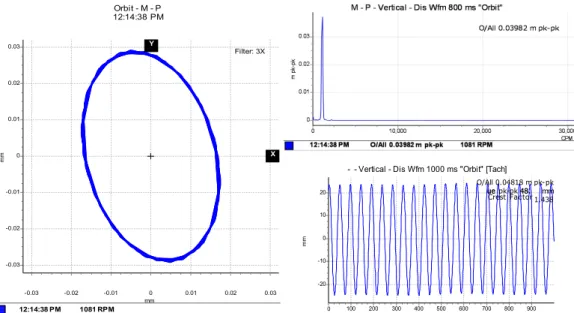
3.3.1.Responses of the vibration of the balanced system
Orbit - M - P 12:14:38 PM 0.03 0.02 0.01 0 -0.01 -0.02 -0.03 -0.03 -0.02 -0.01 0 0.01 0.02 0.03 mm mm 12:14:38 PM 1081 RPM Y Filter: 3X X
- - Vertical - Dis Wfm 1000 ms "Orbit" [Tach] O/All 0.04818 m pk-pk ue 48. mm 20 1.438 10 0 -10 -20 0 100 200 300 400 500 600 700 800 900 ms mm ue pk-pk 48. Crest Factor
Fig. 4. Vibration spectrum signal of the secondary shaft with balance condition Y Orbit - M - P 4:19:33 PM lter: 1X 0.04 0.02 0 -0.02 -0.04 -0.04 -0.02 0 0.02 0.04 mm mm 4:19:33 PM 1081 RPM Y Fi X
M - P - Vertical - Dis Wfm 800 ms "Orbit" 0.02 0.015 0.01 0.005 0 0 10,000 20,000 30,000 CPM mp k -p k 4:19:33 PM O/All 0.02566 m pk-pk 1081 RPM O/All 0.02566 m pk-pk
- - Vertical - Dis Wfm 1000 ms "Orbit" [Tach]
15 25 pk 30.51 mm 10 Crest F t 5 0 -5 -10 -15 0 100 200 300 400 500 600 700 800 900 ms mm O Tr/All 0.0ue pk-pk ac or 1.679
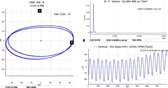
Fig. 5. Vibration spectrum signal of the driver shaft with one unbalancing mass attached to the shaft disc
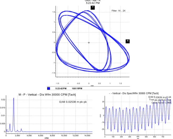
on phenomena of appearance of spectral frequencies, the geometry of the orbits, and the displacement of both rotors as a function of time as well as different parameters that can represent the effect of unbalance and coupling joint on the performance of the system. The experimental results obtained for various parameters of rotors operation studies can be visualized in Fig. 5 and Fig. 6. Orbit - Ral - R 5:23:42 PM 1.5 1 0.5 0 -0.5 -1 -1.5 -1.5 -1 -0.5 0 0.5 1 1.5 mm 5:23:42 PM 1081 RPM Filter: 1X .. 2X X Y
M - P - Vertical – Dis Wfm 30000 CPM [Tach]
0.02 0.015 0.01 0.005 0 0 2,000 4,000 6,000 8,000 10,000 12,000 14,000 CPM mp k-pk O/All 0.02538 m pk-pk
- - Vertical - Dis Spec/Wfm 30000 CPM [Tach] .03636 m p pk-pk 50.61 mm 20 tor 1.968 10 0 -10 -20 0 100 200 300 400 ms 500 600 700 mm O/All 0 True k-pk Crest Fac
Fig. 6. Vibration spectrum signal of the driven shaft with one unbalancing mass attached to the shaft disc
3.4.Findings and analysis of experimental results
Attempts were made to extract features that are characteristic of the unbalance by following the same balancing procedure described in the above experiment. As far as the frequency content is concerned, in the case of balanced masses systems (Fig. 3 and Fig. 4), the presence of the unique rotation frequency of approximately 2.475 Hz and the stability of the orbits of the shaft centre which is splitting in two are verified. This confirms the accuracy of the numerical frequency content obtained in the numerical analysis.
In the case of unbalanced masses, as illustrated in Fig. 5 and Fig. 6, the evolution of the equilibrium position and the amplitude of the orbit as a function of the speed of rotation and the unbalance is plotted. At a suitable speed angular, the amplitude of the trajectory of the shafts increases under the effect of the offset angle of the joint and the eccentric mass, which intuitively is correct taking into account the increase in kinetic energy. Considering the angle of the connecting joint and the unbalance intensity, it can be seen that the Hooke‘s joint will increase the amplitude of vibration and thus, as the case may be dampened or amplified the frequency responses of the rotor, which may lead to the instability of the rotating member. Indeed, on the frequency analysis, one can observe the same features in terms of excitation at 2.475 Hz and 4.96 Hz corresponding to the whirl and few very close superharmonics. At this speed, the
influence of the connection joint consists of disturbing and amplifying the phenomenon induced by the unbalance. The movement is disordered and has many sub-orbits in contrast to the case of the first shaft where disturbances due to the bearing are less important. The orbits are much wider and scattered in several loops. Thus, it is found that the rotor is not excited in the same way according to the plans, this highlights the nonlinear behaviour due to the misalignment, the self-aligned bearing and the non-consideration of the gyroscopic effects.
4.Conclusions
Experimental tests on the two shafts coupled by a Hooke's joint made it possible to observe the phenomena of fluctuation of the signal by various means of visualization (orbits, time-deflection and frequency spectrum analysis). The numerical study conducted for the comparison to the tests was intended to establish trends to validate the mathematical model. There are two main frequencies (Figs. 5 and 6): one due to the excitation by the structure of the rigid body modes of the rotor and the other near half the first frequency of rotation whatever the speed of the rotor. The identification of non-linear phenomena and their origins has been made. As far as the orbits and frequency spectrum content are concerned, the presence of the rotation frequency of approximately 2.475 Hz, the half rotation frequency, the multiples of the rotation frequency and the splitting of the orbits are verified. This confirms the predictions as to the accuracy of the proposed interconnected twin-rotor through Hooke’s joint.
Acknowledgement
The authors acknowledge the Faculty of Engineering and Technology, Vaal University of Technology, South Africa, for facilitating this research.
References
[1] Yamamoto G. K., Da Costa C., Da Silva Sousa J. S. A smart experimental setup for vibration
measurement and imbalance fault detection in rotating machinery. Case Studies in Mechanical Systems and Signal Processing, Vol. 4, 2016, p. 8-18.
[2] Maccamhaoil M. Static and Dynamic Balancing of Rigid Rotors. Bruel & Kjaer Application Notes,
2012.
[3] Tchomeni B. X., Alugongo A. Numerical and experimental diagnosis of complex rotor system by