AALTO UNIVERSITY
School of Electrical Engineering
Department of Communications and Networking
Lasse Laine
Performance Management of 3
rdGeneration Partnership
Project Long Term Evolution
Master's Thesis submitted in partial fulfillment of the degree of Master of Science in Technology
Espoo, 27th September 2011
Supervisor: Prof. Jyri Hämäläinen Instructor: M.Sc. Osman Yilmaz
i AALTO UNIVERSITY
Abstract
Author:Name off the Thesis:
Lasse Laine
Performance Management of 3rd Partnership Project Long Term Evolution
Date: 27 September 2011 Number of pages: 11 + 96 = 107 Department:
Degree Programme:
Department of Communications and Networking Degree Programme in Communications Engineering Supervisor:
Instructor:
Prof. Jyri Hämäläinen M.Sc. Osman Yilmaz
Long Term Evolution (LTE) is the newest mobile network standard in the 3rd Generation Partnership Project (3GPP) evolution path, promising to considerably increase the performance of mobile networks. Building a mobile network is a huge investment for a network operator, and naturally operators try to maximize the revenue and minimize the operational expenditure created by their investment. This goal can be achieved by optimizing network performance and by minimizing the manual effort of network management.
This thesis introduces the most important key performance indicators (KPI) of LTE, which can be utilized to evaluate network performance. Self-Organizing-Networks (SON) concept designed to automate many of the network management tasks is also described. Furthermore, the feasibility, advantages and disadvantages of SON use cases are evaluated.
The final part of the thesis reports research carried out on the Cell Outage Compensation (COC), a SON use case designed to alleviate the effect of a network outage. The research, which was carried out using system level simulations, consisted of investigating the effects of a typical outage, selecting the most potential control parameters and developing a COC function. As a result, the developed COC function considerably alleviated the effects of the outage in the utilized simulation environment.
ii AALTO-YLIOPISTO
Tiivistelmä
Tekijä: Työn nimi: Lasse Laine3rd Generation Partnership Project Long Term Evolution
-mobiiliverkon suorituskyvyn hallinta
Date: 27.09.2011 Number of pages: 11 + 96 = 107 Laitos:
Tutkinto-ohjelma:
Tietoliikenne ja tietoverkkotekniikan laitos Tietoliikennetekniikan tutkinto-ohjelma Työn valvoja:
Työn ohjaaja:
Prof. Jyri Hämäläinen DI Osman Yilmaz
Long Term Evolution (LTE) on 3rd Generation Partnership Project:in (3GPP) uusin, suorituskyvyltään edeltäjiään huomattavasti kehittyneempi mobiiliverkkostandardi. Verkon rakentaminen on operaattorille aina valtava investointi, jonka vuoksi operaattorit luonnollisesti haluavat maksimoida verkon tuoton samalla minimoiden sen ylläpitämisen aiheuttamat kustannukset. Verkon tuottoa voidaan parantaa optimoimalla sen suorituskykyä ja verkon ylläpitokustannuksia pienentää automatisoimalla verkonhallinnan toimintoja.
Ratkaiseva vaihe verkon suorituskyvyn optimointiprosessissa on verkon suorituskyvyn arviointi. Tässä diplomityössä kuvataan LTE:n tärkeimmät verkon suorituskyvyn tunnusluvut, joiden avulla verkon toimintaa voidaan arvioida kokonaisvaltaisesti. Lisäksi diplomityössä esitellään verkonhallinnan toimintoja automatisoiva Self-Organizing-Networks (SON) -konsepti ja sen tyypilliset käyttösovellukset. Työssä arvioidaan myös näiden käyttösovellusten toteuttamiskelpoisuutta, vahvuuksia sekä heikkouksia.
Diplomityön viimeisessä osassa tutkitaan järjestelmätason simulaatioiden avulla SON -konseptin Cell Outage Compensation (COC) -käyttösovellusta, jonka tavoitteena on vähentää tukiasemien vikaantumisista verkon käyttäjille aiheutuvaa haittaa. Osiossa tutkitaan tyypillisen vikaantumisen vaikutuksia, valitaan kontrolliparametrit COC algoritmille sekä kehitetään COC funktio. Tehdyissä simulaatioissa kehitetty COC -funktio onnistui vähentämään vikaantumisen vaikutuksia merkittävästi.
iii
Preface
I would like to thank Professor Jyri Hämäläinen for the supervision of this thesis and for the thorough answers to my questions. Also my instructor, M.Sc. Osman Yilmaz, has my gratitude for his supporting comments and his enthusiasm towards the subject. As this thesis was funded by Omnitele Ltd., I am grateful for both the opportunity and the resources provided for the thesis. It has been extremely educating and rewarding to work among the highly competent personnel of Omnitele and to investigate an extremely interesting subject. Especially, I would like to thank B.Sc. Jarkko Heikkinen for the time and effort he has used for aiding me during the thesis writing process. I also would like to express my gratitude to all of my friends for helping me out during the writing process. Finally, I want to thank Ms. Heini Hyttinen for her unselfish aid during the thesis writing process. Her help has been invaluable for the success of the project and for the wellbeing of the writer.
Helsinki, 27 September 2011 Lasse Laine
iv
Table of Contents
Abstract ... i Tiivistelmä...ii Preface ... iii Table of Contents ... iv List of Abbreviations ...v List of Symbols ... ix 1 Introduction ... 12 Long Term Evolution ... 3
2.1 Network Architecture ... 3
2.2 Air Interface in LTE DL: Orthogonal Frequency Division Multiple Access ... 4
2.3 Air Interface in LTE UL: Single-Carrier Frequency Division Multiple Access ... 8
2.4 Multiple-Input Multiple-Output Schemes ... 9
2.5 Inter-Cell Interference Coordination ... 11
2.6 Bearers ... 14
2.7 Mobility ... 15
2.8 LTE Processes ... 17
3 Optimization of the Long Term Evolution ... 27
3.1 Integrity KPIs ... 27 3.2 Accessibility KPIs... 31 3.3 Retainability KPIs ... 35 3.4 Mobility KPIs ... 36 4 Self-Organizing-Networks ... 40 4.1 SON Architectures ... 40
4.2 SON Use Cases ... 43
5 Cell Outage Compensation ... 53
5.1 Introduction ... 53
5.2 Cell Outage Compensation Objectives ... 53
5.3 Simulation Environment ... 54
5.4 Simulation Process ... 57
5.5 Effects of an Outage ... 58
5.6 Cell Outage Compensation Group and Control Parameters ... 63
v
6 Conclusions ... 78
References ... 79
Appendix A - Timers ... 82
Appendix B - Typical causes for attach rejections ... 83
Appendix C - Typical causes for PDN connectivity request rejections ... 84
Appendix D - Typical causes for default EPS bearer context activation request rejections ... 86
Appendix E - Typical causes for bearer resource allocation request rejections ... 87
Appendix F - Typical causes for dedicated EPS bearer context activation request rejections ... 88
Appendix G - Typical causes for dedicated EPS bearer context modification request rejections ... 89
Appendix H - Typical causes for EPS bearer deactivations ... 90
Appendix I - Effects of the outage to the DL performance in scenario I ... 91
Appendix J - Effects of the outage to the UL performance in scenario I ... 93
Appendix K - Effect of the outage to the DL performance in scenario II... 94
vi
List of Abbreviations
3GPP 3rd Generation Partnership Project
ANR Automated Neighbor Relations
APN Access Point Name
ARP Allocation and Retention Priority
CCO Capacity and Coverage Optimization
CCU Cell Center Users
CEU Cell Edge Users
COC Cell Outage Compensation
COD Cell Outage Detection
COM Cell Outage Management
CPICH Common Pilot Channel
C-RNTI Cell Radio Network Temporary Identifier
CSG Closed Subscriber Group
DHCP Dynamic Host Configuration Protocol
DL Downlink
DM-RS Demodulation Reference Symbol
EDGE Enhance Data rates for Global Evolution
eNodeB Evolved NodeB
EPC Evolved Packet Core
E-RAB E-UTRAN Radio Access Bearer
ESM EPS Session Management
E-UTRAN Evolved Universal Terrestrial Radio Access Network
FDD Frequency Division Duplexing
vii
GBR Guaranteed Bit Rate
GERAN GSM/EDGE Radio Access Network
GSM Global System for Mobile Communications
HSDPA High-Speed Downlink Packet Access
HSS Home Subscriber Server
ICI Inter-Carrier Interference
ICIC Inter-Cell Interference Coordination
IP Internet Protocol
ISI Inter-Symbol Interference
KPI Key Performance Indicator
LTE Long Term Evolution
MBR Maximum Bit Rate
MCS Modulation and Coding Scheme
ME Mobile Equipment
MHA Mast Head Amplifier
MIMO Multiple-Input Multiple-Output
MME Mobility Management Entity
NR Neighbor Relation
NRT Neighbor Relation Table
OFDMA Orthogonal Frequency Division Multiple Access
O&M Operation and Maintenance
PCI Physical Cell Identity
PDN Packet Data Network
P-GW PDN Gateway
PLMN Public Land Mobile Network
viii
QAM Quadrature Amplitude Modulation
QCI QoS Class Identifier
QoS Quality of Service
RAN Radio Access Network
RAT Radio Access Technology
RLC Radio Link Control
RLF Radio Link Failure
RNC Radio Network Controller
RRC Radio Resource Control
RSCP Received Signal Code Power
RSRP Reference Signal Received Power
RSRQ Reference Signal Received Quality
RSSI Received Signal Strength Indicator
RTT Round Trip Time
SC-FDMA Single-Carrier Frequency Division Multiple Access
SDF Service Data Flow
S-GW Serving Gateway
SINR Signal-to-Interference-plus-Noise Ratio
SON Self-Organizing-Networks
SRS Sounding Reference Symbol
TCP Transmission Control Protocol
TFT Traffic Flow Template
TIBC Time-In-Best-Cell
UDP User Datagram Protocol
UE User Equipment
ix
UMTS Universal Mobile Telecommunications System
USIM Universal Subscriber Identity Module
UTRAN Universal Terrestrial Radio Access Network
x
List of Symbols
A threshold utilized in absolute priority based reselections when UE is moving into a higher priority layer
Cell reselection timer utilized in absolute priority based reselections
A threshold utilized in absolute priority based reselections when UE is moving into a lower priority layer
RSRP value the target cell RSRP offset
RSRP value of the serving cell RSRP hysteresis
Cell reselection timer utilized in equal priority reselections
/ Pilot signal energy of the CPICH within one chip duration
divided with RSSI
RSRQ threshold utilized in RLF detection when timer T300 is running
RSRQ threshold utilized in RLF detection when timer T300 is not running
Path loss
1 Intercept parameter of the path loss
2 Slope parameter of the path loss
Distance between two nodes
3 UE antenna height correction factor
UE antenna height above ground level
4 UE antenna height correction factor
5 Effective eNodeB height correction factor
xi
6 Correction factor of effective eNodeB height and distance
between UE and eNodeB
7 Diffraction loss correction factor
Diffraction loss Clutter loss
UL MBR reduction step size
Amount of time the data is gathered for an optimization decision
Minimum acceptable average UL throughput
Intercept parameter of the UL SINR failure probability UL interference correction factor
UL interference
UL SINR failure probability R-Squared
Simulated failure probability Estimated failure probability
Average of the simulated failure probabilities F value
The number RSRP level changes per optimized cell RSRP level reduction step size
Minimum improvement in the total failure rate to declare an optimization step successful
1
Introduction
Mobile networks are nowadays a significant part of our everyday life. Although the mobile networks have existed for a long time, the user requirements have changed radically in recent years. An increased number of users, new service types, smartphones and integrated laptop modem chips have introduced high capacity and service quality requirements for the mobile networks, forcing the operators to either constantly update their existing networks or to invest into new network technologies. The most widely utilized mobile network evolution path is based on the standards created by 3rd Generation Partnership Project (3GPP), which is a collaboration of multiple significant telecommunication associations. The newest mobile network standard in the 3GPP evolution path, promising to raise the performance of the mobile networks into a new level, is called the Long Term Evolution (LTE). Compared to previous 3GPP mobile network technologies, LTE offers multiple improvements, such as higher spectral efficiency, simpler network architecture and lower operational expenditure. The details of LTE are defined in 3GPP technical specification releases eight and nine, which can be freely downloaded from the 3GPP Internet site.
A mobile network is an enormous investment for a network operator. Similarly to any other company, operators try to maximize the revenue and minimize the operational expenditure created by their investment. Parameterization changes, software updates and hardware improvements are executed constantly to optimize the network performance, resulting in higher revenues. Naturally, the optimization of the network increases also the operational expenditure, and therefore operators must constantly estimate which optimization decisions are actually profitable and which are not. A concept of Self-Organizing-Networks (SON), which is seamlessly attached as a part of LTE, attempts to decrease the mobile network operational expenditure, by automating the network management tasks. A network which configures itself, optimizes itself and recovers automatically from failure situations is the ultimate goal of the SON.
The main goal of the thesis is to study: How to improve the performance and the user experienced quality of service of an LTE network? The thesis consists of six chapters, each having separate goals and significance in the overall structure. The first chapter describes the background, the basic concepts, the motivation and the structure of the thesis, giving a solid insight to the reader about the scope of the thesis. In the second chapter, LTE is investigated from a technical perspective. The network architecture and the radio access schemes, both in Uplink (UL) and Downlink (DL), are described and their advantages and disadvantages are evaluated. In addition, the basis of LTE Multiple-Input Multiple-Output (MIMO) and Inter-Cell Interference Coordination (ICIC) schemes are introduced. Furthermore, overviews concerning LTE bearer structures and the most significant processes are given. The goal of the second chapter is to familiarize the reader with LTE characteristics, advantages, disadvantages and
2
differences compared to previous 3GPP mobile network technologies. Understanding the contents of the chapter two is crucial for the understanding of the subsequent chapters.
In the chapter three, basic optimization guidelines for LTE networks are described. The chapter introduces main LTE key performance indicators (KPI) and describes how network performance and user experienced quality of service can be evaluated based on the selected KPIs. In addition, for each KPI a comparison to UMTS (Universal Mobile Telecommunications System), a legacy 3GPP system, is executed to highlight the differences and the similarities between UMTS and LTE. The goal of the chapter three is to introduce the basics of LTE network performance evaluation/optimization and to familiarize the reader with the main KPIs of LTE.
In the chapter four, the SON concept is presented. Different architectural approaches are introduced and their advantages and disadvantages are evaluated. In addition, the most typical SON use cases are described and their usefulness and feasibility are investigated. Furthermore, an insight about the commonness of the SON features in real networks is given. The goal of the chapter four is to familiarize the reader with the SON concept and its typical use cases and to give an understanding about the possibilities and challenges related to SON.
In the chapter five, the feasibility and the potential of one of the SON use cases, the Cell Outage Compensation (COC), are investigated with network level simulations. The beginning of the chapter describes the goals of the COC, the simulation process and the simulation environment. In addition, the effects of a typical outage to the network performance and the user experienced quality of service are investigated. Based on these results, COC control parameters (parameters which are adjusted in an outage situation) are selected and their feasibility is tested utilizing network level simulations. Finally, a COC algorithm based on the selected control parameters is developed and tested utilizing the simulation environment described in the chapter five. Chapter six concludes the thesis and summarizes the most important findings.
3
Long Term Evolution
To fulfill the high capacity and service quality requirements of the mobile networks, LTE has many significant differences compared to the legacy mobile network technologies. This chapter introduces the main features, development decisions, advantages and disadvantages of LTE, and gives a solid basis for the reader to understand the subsequent chapters of the thesis.
2.1 Network Architecture
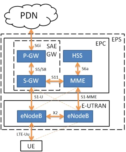
The main trend of reducing complexity of the network can be clearly seen in the LTE network architecture. Firstly, there is no circuit switched domain in LTE. All of the services are carried out using packet switched services, which simplifies the network greatly and allows more efficient optimization of the packet switched services. Secondly, the number of network elements is reduced compared to the legacy systems. Instead of centralized Radio Network Controllers (RNC), all radio related protocols are terminated straightly in Evolved NodeBs (eNodeB) enabling improvement on the latencies and optimizing the performance of the network. [1] User Equipment (UE) consists of a mobile client device and a physical card, Universal Subscriber Identity Module (USIM), used to identify and authenticate a particular user. UEs are connected to Evolved Packet Core (EPC) via Evolved Universal Terrestrial Radio Access Network (E-UTRAN), which consists of multiple eNodeBs connected together via X2 interfaces. eNodeBs manage all the radio access related protocols and tasks, such as radio resource management, handover control, admission control and scheduling. As a comparison to UMTS system, eNodeBs handle similar tasks than NodeBs and RNCs in an UMTS network. [2] [3]
EPC delivers the user traffic between Packet Data Network (PDN) and E-UTRAN. EPC consists of three main elements: Mobility Management Entity (MME), Serving Gateway (S-GW) and PDN Gateway (P-GW). MME is the main control entity of EPC, and responsible for user authentication, mobility management, service tracking, subscription profile management and service connectivity. Functions requiring subscriber profile information are done by interacting with Home Subscriber Server (HSS). S-GW is responsible for forwarding and routing user packets and being a mobility anchor during handovers between LTE and other 3GPP networks. P-GW operates as an edge-router between EPC and PDN. It is typically the point of attachment for UEs and responsible for IP (Internet Protocol) address allocations. In addition, P-GW performs packet filtering and traffic shaping according to the active policies. The whole packet system consisting of EPC and E-UTRAN is denoted as Evolved Packet System (EPS). LTE system architecture and the related interfaces are illustrated in figure 1. [3]
4
Figure 1. LTE system architecture.
2.2 Air Interface in LTE DL: Orthogonal Frequency Division
Multiple Access
2.2.1 Carrier Structure and Inter-Carrier Interference
Frequency Division Multiple Access (FDMA) is a common multiple access method in cellular networks. One main problem of the traditional FDMA is the power leakage between adjacent subcarriers, which causes Inter-Carrier Interference (ICI). To tackle the signal degradation caused by ICI, guard bands must be introduced between subcarriers. Within these guard bands no information can be sent, and therefore they waste the capacity of the system. The insight behind the DL multiple access method of LTE, Orthogonal Frequency Division Multiple Access (OFDMA), is to use a subcarrier spacing, which makes the power of the neighboring subcarriers zero at the sampling instant of the desired subcarrier [1]. With this method, although the envelopes of the subcarriers reach the frequency band of the adjacent subcarriers, no ICI is created. Therefore, subcarriers can be packed close to each other and no guard bands are needed. As a downside, the orthogonality of the adjacent subcarriers depends highly on the accuracy of the frequency synchronization. Inaccurate synchronization introduces ICI and can be caused by, for example, inaccuracy of the local oscillators or the Doppler Effect. The subcarrier structure of OFDMA is illustrated in figure 2.
5
Figure 2. Subcarrier structure of OFDMA.
2.2.2 Frame Structure, Cyclic Prefix and Inter Symbol Interference
In the time domain, the transmissions of each subcarrier can be divided into frames with a length of 10 ms, which further can be divided into 1 ms subframes. Each subframe consists of two 0.5 ms time slots, which in turn build up from seven data symbols [4] [5]. In a typical radio environment, multiple delayed copies of the transmitted symbols are seen at the receiver as an effect of the multipath fading. These copies sum up causing Inter-Symbol Inference (ISI) between the symbols. To mitigate the effects of ISI, a cyclic prefix is added at the beginning of every symbol. The length of the cyclic prefix is determined by the delay characteristic of the radio channel. Ideally, all delayed copies of the transmitted symbol are received during the cyclic prefix, and therefore just by ignoring the cyclic prefix, the ISI can be mitigated. LTE introduces two different cyclic prefix lengths: normal and extended. In the normal mode, the cyclic prefix length of the first symbol in a time slot is 5.2 µs and for other six symbols 4.7 µs. In extended mode, the cyclic prefix length is 16.7 µs for all symbols [5]. The length of the cyclic prefix is a tradeoff between the capacity and the maximum tolerable delay variation of different radio paths between the transmitter and the receiver. If the delay variation of the radio paths exceeds the maximum allowed value, delayed signal components from the previous symbols will degrade the quality of the current symbol. The relations between the cyclic prefix length, the maximum allowed distance difference between the radio paths and the proportional capacity used for the cyclic prefix at the physical layer are illustrated in table 1. It should be noted, that the maximum cell size is typically much bigger than the maximum distance between radio paths, although these values are typically strongly correlated.
6
Table 1. The effects of the cyclic prefix length to the maximum allowed radio path difference and capacity utilized for the cyclic prefix.
Cyclic prefix Max. distance difference Capacity used for
length between the radio paths the cyclic prefix
4.7 µs / 5.2 µs 1406 m 7 %
16.7 µs 5000 m 23 %
2.2.3 Resource Allocation and Reference Symbols
In OFDMA of LTE, subcarriers can be allocated to different users with a granularity of 12 subcarriers, resulting in the smallest possible allocation unit of 180 kHz in the frequency domain. In the time domain, resources can be allocated with an accuracy of a subframe, resulting in a smallest allocation time of 1 ms. Therefore, the basic allocation unit, denoted as a resource block, consists of 180 kHz bandwidth and 1 ms time. These resource blocks can basically be allocated to the users in an arbitrary manner, but the actual implementation of the resource scheduler can have some limitations.
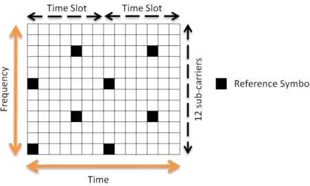
As mentioned in sections 2.2.1 and 2.2.2, the orthogonality of the subcarriers diminishes the ICI and the use of the cyclic prefixes diminishes the ISI. However, even without ICI and ISI the symbols change during the transmission, since the radio channel between the transmitter and the receiver changes the phase and the amplitude of every symbol. In LTE, a part of the transmitted symbols are reference symbols, which original amplitude and phase are known to the receiver. With the help of these symbols, the receiver can estimate the original content of the received symbols. An example of the reference symbol structure is illustrated in figure 3. [1] [6]
7
The accuracy of the channel estimation depends on the utilized number of reference symbols. Obviously, the denser the reference symbol grid is, the more accurately the channel can be estimated. On the other hand, reference symbols cannot be used to transmit user information, and therefore they are purely overhead traffic consuming the capacity of the system. The density of the reference symbol grid is determined by the assumed coherence time/frequency of the channel. If the channel changes rapidly as a function of time/frequency, a dense symbol grid is required. In contrast, with a slowly changing channel, much sparser symbol grid is adequate.
In addition to channel estimation, reference symbols are used for cell (re)selection and handover processes. UE measures constantly the average power of the reference symbols, denoted as Reference Signal Received Power (RSRP), from the serving and the adjacent cells. These measurements are used to determine the cell with the strongest signal. Furthermore, an estimate of the quality of the received signal, Reference Signal Received Quality (RSRQ), is calculated by dividing the RSRP value with a Received Signal Strength Indicator (RSSI). RSSI is a measure of the total received wideband power. [1]
2.2.4 OFDMA Advantages and Disadvantages
The multi-carrier transmission scheme of OFDMA enables multiple advantages compared to the legacy systems, particularly to WCDMA (Wideband Code Division Multiple Access) utilized in UMTS. Since in WCDMA all transmissions occupy the whole available bandwidth, the utilization of frequency diversity is impossible. Due to this fundamental restriction, even the latest technology improvement of UMTS, HSDPA (High-Speed Downlink Packet Access), can schedule the user transmissions only in time and code domain. In OFDMA, resource blocks can be allocated to the users in an arbitrary way, and therefore OFDMA can utilize both time and frequency diversity efficiently. This is a major reason for the higher spectral efficiency of LTE DL compared to UMTS DL, especially in frequency fading channels. Another main advantage of OFDMA is its capability to utilize flexibly various system bandwidths while keeping the receiver complexity at a rather low level. As a comparison in WCDMA, an increase in the system bandwidth increases drastically the complexity of the receiver due to the increased number of multipath components. [7] [8]
Main disadvantages of OFDMA are the sensitivity to the frequency synchronization errors and a high peak-to-average power ratio. In the time domain, the OFDMA transmissions consist of multiple sinusoidal signals, which are summed together. The resulting signal varies strongly, leading to a high difference between the average transmitted power and the highest transmitted power. In practice, high peak-to-average ratio increases the power consumption and the cost of the transmitter. However, these are not critical problems, since the transmitter lies in the eNodeB. [9]
8
2.3 Air Interface in LTE UL: Single-Carrier Frequency Division
Multiple Access
2.3.1 Characteristic of SC-FDMA and Differences to OFDMA
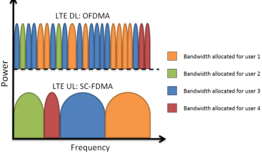
High peak-to-average ratio, inevitably leading to poor power efficiency, was the main reason for not choosing OFDMA as the multiple access method for the LTE UL. Instead, a multiple access method called Single-Carrier Frequency Division Multiple Access (SC-FDMA) was selected. SC-FDMA has many desirable characteristics similar to OFDMA, but does not suffer from a high peak-to-average ratio. In SC-FDMA, the information of a user is sent utilizing only a single carrier. Similarly to OFDMA, the basic resource allocation unit is a resource block, consisting of a 180 kHz bandwidth and duration of 1 ms [1]. These resource blocks can be allocated to the users in an arbitrary way, as long as the allocated bandwidth is continuous. Therefore, SC-FDMA can utilize frequency diversity to achieve diversity gain; however, not as efficiently as OFDMA, since the degree of freedom in the resource block allocation is smaller. Similarly to OFDMA, there is no need to allocate guard bands between the carriers, since SC-FDMA carriers are based on a similar subcarrier structure than the subcarriers of OFDMA. The comparison between OFDMA and SC-FDMA carrier structure is illustrated in figure 4. [3] [8]
Figure 4. The difference between OFDMA and SC-FDMA carrier structures. The symbol rate of SC-FDMA is much higher than the symbol rate of OFDMA, since the information of an individual user is sent via a single carrier instead of utilizing multiple carriers. Similarly to OFDMA, cyclic prefixes are added periodically to mitigate ISI. As a difference, cyclic prefixes are added only after a block of symbols, rather than after every symbol. As a result, only the ISI between the symbol blocks can be mitigated by ignoring the cyclic prefix at the receiver side and the ISI between adjacent symbols must be handled by the receiver. In practice, the receiver must be able to equalize the whole block of symbols, instead of just processing one symbol at a time [1]. This
9
inevitably leads to a more complex receiver implementation than in OFDMA, which on the other hand is not a critical problem, since the receiver lies in the eNodeB. [8] [10] Similarly to OFDMA, reference symbols are used in SC-FDMA to enable channel estimation. There are two reference symbol types in SC-FDMA: Demodulation Reference Symbols (DM-RS) and Sounding Reference Symbols (SRS). DM-RSs are used to enable coherent signal demodulation at the receiver side. DM-RSs are multiplexed in time domain into a SC-FDMA radio frame, similarly to any other symbols. Depending on the cyclic prefix length (normal or extended), third or fourth symbol of the frame is used. DM-RSs cannot be used for the purposes of frequency selective scheduling, because they are transmitted utilizing a bandwidth allocated to a particular user. To enable efficient frequency selective scheduling, SRSs can be sent periodically using a wider bandwidth. Using SRSs is not mandatory in the 3GPP specification of LTE, as they reduce the capacity of the cell by approximately 7 % [10]. However, SRSs do enable more efficient allocation of the bandwidth resources, which results in more efficient utilization of the frequency diversity. The reference symbol structure of LTE SC-FDMA is illustrated in figure 5. [11]
Figure 5. SC-FDMA reference symbol structure.
2.4 Multiple-Input Multiple-Output Schemes
MIMO schemes are one of the main innovations of LTE improving the spectral efficiency, the coverage and the peak rates of the network. MIMO technologies have been utilized also in legacy technologies, but in LTE the full support for MIMO features have been an essential design aspect from the beginning of the 3GPP standardization process. Different MIMO schemes, including spatial multiplexing, multi-user spatial multiplexing and transmit diversity can be used adaptively according to instantaneous channel conditions to boost the performance of the network. This section introduces the basic MIMO schemes utilized in LTE.
10 2.4.1 Spatial Multiplexing
Spatial multiplexing is used to create multiple parallel transmission channels between the receiver and the transmitter, without allocating any additional bandwidth resources. This is done by using multiple receiver and transmitter antennas. All transmitter antennas transmit different information, and with the means of signal processing, streams are separated at the receiver. Separation process is based on reference symbols described in section
2.2.3. At its best, spatial multiplexing doubles the peak rates when using two parallel streams (requires two receiver and two transmitter antennas) or increases the peak rates by a factor of four when using four parallel streams (requires four receiver and four transmitter antennas). [1]
In practice, spatial multiplexing can only be used relatively close to the cell center, because it requires high Signal-to-Interference-plus-Noise Ratio (SINR) to work properly. This is due to two main reasons. Firstly, the total transmission power is divided between the transmitter antennas. If two transmitter antennas are used, the transmitted power drops 3 dB and in the case of four transmitter antennas, the reduction in the transmitted power is 6 dB. Secondly, as the parallel data streams use the same physical resources, they also create interference to each other. As the MIMO stream separation is based on the channel response differences, strong correlation between the transmission channels leads to strong inter-stream interference, and weak correlation to weak inter-stream interference. [12]
As the UEs typically have only one transmission antenna, spatial multiplexing cannot be utilized in the UL direction. However, to enable a part of the spatial multiplexing benefits, a transmission method called multi-user spatial multiplexing can be used. The basic idea of the multi-user spatial multiplexing is to utilize normal spatial multiplexing principle with two different UEs. In contrast to normal spatial multiplexing, which increases the peak rates of individual users and the capacity of the network, multi-user spatial multiplexing increases only the overall network capacity. Multi-user spatial multiplexing principle is illustrated in figure 6. [13]
11 2.4.2 Transmit and Receive Diversity
Macro diversity can be utilized either by sending the same signal via multiple transmitter antennas (transmit diversity) or by using multiple receive antennas for the signal reception (receive diversity). [14] By separating the antennas in space, the probability of deep fading dips in the received signal power can be reduced, since individual stream fade differently. The amount of gain depends on the correlation of the individual channels – more correlation exists, less gain can be achieved. Transmit/receive diversity is typically used for the cell edge users, whose achievable SINRs are relatively small. With the increase in SINR, cell range and capacity of the network can be increased.
2.5 Inter-Cell Interference Coordination
LTE network without any ICIC is basically a reuse one system, where every part of the available bandwidth is utilized equally. The main problem in this approach is the cell edge users experiencing heavy DL interference and also creating considerably amount of UL interference. As LTE is a multi-carrier technology, frequency utilization of adjacent cells can be easily coordinated to minimize the Inter-Cell Interference. The characteristics of four basic LTE ICIC methods are described in this section.
2.5.1 Hard Frequency Reuse
In hard frequency reuse, the available bandwidth is divided into exclusive segments allocated to individual cells in a way, that the adjacent cells do not utilize the same bandwidth segment. A parameter denoted as reuse factor defines the number of frequency segments [15]. With hard frequency reuse, the interference can be effectively diminished both in UL and DL, but at the cost of a major reduction in the system capacity, since only a part of the total bandwidth can be utilized in an individual cell. Since the system capacity drops with a factor equal to the reuse factor, hard frequency reuse cannot be seen as a practical ICIC scheme. In this thesis, it is only presented to provide a baseline when evaluating the more advanced ICIC schemes. Hard frequency reuse using reuse factor three is illustrated in figure 7.
12
2.5.2 Prioritization
In prioritization scheme, the whole bandwidth can be utilized in all cells similarly to a network without any frequency coordination. As a difference, a prioritized bandwidth segment has been defined for each cell, into which the transmissions are prioritized over the rest of the bandwidth. The prioritization is done in a way, that the adjacent cells do not utilize the same bandwidth segments. [16] With prioritization, the probability of adjacent cells utilizing the same resource block is smaller than without prioritization, and therefore it can be used to diminish interference both in UL and DL. Prioritization works effectively with low network loads, but as the network load increases, the probability of adjacent cells utilizing the same resource blocks also increases. In a fully loaded network, prioritization does not offer any gain compared to a network without prioritization. Prioritization using three prioritization partitions is illustrated in figure 8.
Figure 8. Prioritization scheme. 2.5.3 Fractional Frequency Reuse
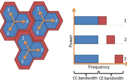
In fractional frequency reuse, the available bandwidth is divided into segments, in which varying frequency reuse schemes can be utilized. Typically, the bandwidth is divided into two parts: the first part is allocated to the Cell Center Users (CCU) and the second part to the Cell Edge Users (CEU). As the CEU experience higher interference levels than the CCU, it is purposeful to use higher reuse factors for the CEUs than for the CCUs. In a typical fractional reuse scheme, reuse factors one and three are utilized in the cell center and the cell edge respectively. [17] If the utilized reuse factors are higher than one, fractional reuse decreases the spectral efficiency of the network; however, not as much as hard frequency reuse. Therefore, the performance of fractional reuse can be seen as a compromise between the spectral efficiency and the cell edge performance. Fractional frequency reuse principle is illustrated in figure 9.
13
Figure 9. Fractional frequency reuse scheme. 2.5.4 Soft Frequency Reuse
In a basic soft frequency reuse scheme all cells can utilize the whole available bandwidth, but for each cell an individual power spectrum has been defined. The power spectrums are chosen in a way, where the probability of overlapping high power transmission is small. [17] With this method, the probability of adjacent cells utilizing the same resource block does not decrease, but the effects of a collision are smaller. As a result, the interference decreases effectively both in UL and DL. As a major benefit of the soft frequency reuse, the whole bandwidth can be utilized in all cells leading to a high spectral efficiency. Soft frequency reuse is illustrated in figure 10. In addition, combining the basic ICIC schemes described in this section is possible. As an example, an ICIC scheme utilizing prioritization, soft frequency reuse and fractional frequency reuse is illustrated in figure 11.
14
Figure 11. Combination of prioritization, soft frequency reuse and fractional frequency reuse schemes.
2.6 Bearers
A logical connection between two network elements defining the connection points, the traffic profile and the connection parameters is denoted as a bearer. In LTE, the user data is divided into Service Data Flows (SDF) by using Traffic Flow Templates (TFT). TFTs consist of one or multiple filters characterizing the packet types belonging to a particular SDF. TFT binds an SDF into an EPS bearer: a logical connection throughout the whole EPS (between the UE and the P-GW). There are two types of EPS bearers: a default EPS bearer and a dedicated EPS bearer. The default EPS bearer is established in the initial attach process, where the UE registers itself to the MME, and is maintained as long as the user detaches from the network. The main task of the default bearer is to provide IP level connectivity between the UE and the P-GW. All additional EPS bearers, which are established as needed basis, are called dedicated EPS bearers. Every EPS bearer is associated with a Quality of Service (QoS) profile, which includes the following parameters: QoS Class Identifier (QCI), Allocation and Retention Priority (ARP) and Maximum Bit Rate (MBR). In addition, for dedicated EPS bearers a Guaranteed Bit Rate (GBR) can be defined. EPS bearers have a one-to-one mapping to the lower layer bearers and consist of an E-UTRAN Radio Access Bearer (E-RAB) and a S5/S8 bearer. E-RAB is a composition of a radio bearer and a S1 bearer. The bearer architecture is illustrated in figure 12. [18]
15
Figure 12. The bearer architecture of LTE.
2.7 Mobility
Mobility, a functionality providing continuous service to the users moving around in the network, is a fundamental feature of any mobile cellular system. This section introduces mobility principles utilized within E-UTRAN and from E-UTRAN to other Radio Access Technologies (RAT).
2.7.1 Absolute Priority Based Reselection
In a live network, LTE can utilize multiple different bandwidths simultaneously. In addition, operators might have other Radio Access Networks (RAN), such as Universal Terrestrial Radio Access Network (UTRAN) or GSM/EDGE Radio Access Network (GERAN). Each of these technologies/frequencies can be seen as an own layer, creating a layered cell structure to the network. For selecting the most suitable layer, a method known as absolute priority based reselection is implemented into LTE. In the absolute priority based reselection, each of the layers are given a priority, which from UE selects the highest priority layer assuming it can provide a decent level of service.
To determine if the target layer can provide an adequate service level, UE constantly measures the signal strength of the best cell in the target layer. Depending on the target RAT, different metrics are utilized. For example, in LTE the metric is RSRP and in UMTS the metric is the strength of the Common Pilot Channel (CPICH). If the measured
value of the target layer fulfills a threshold for a time of , the
reselection is executed. To make reselections to the lower priority layers, the
measured value of the serving cell must be lower than and the measured
16 2.7.2 Equal Priority Reselection
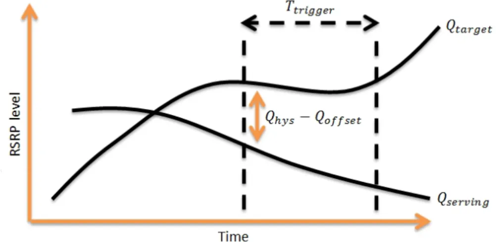
The cell reselections between two equal priority E-UTRAN cells are executed with an algorithm called equal priority reselection, which is based on the RSRP measurements
of the UEs. A reselection is executed to the target cell, if condition + >
+ is fulfilled for a time of , where is the RSRP of the
candidate target cell, is the RSRP of the serving cell, is a hysteresis value
used to avoid ping-pong handovers (back-and-forth handovers), is a
time-to-trigger value used to avoid too frequent handovers and is an offset value used
to bias the handover process towards particular cells. [1] The equal priority reselection condition is illustrated in figure 13.
Figure 13. Equal priority reselection condition.
2.7.3 Handover
A transfer of an active UE connection from a cell to another cell is called a handover. All handovers initiated in LTE are hard, in which the connection between the UE and the RAN is broken for a while during the handover process. For intra-LTE handovers, a typical values for the detach delay (the time there is no connection between UE and RAN) are around 5-30 ms [19] [20]. For inter-RAT handovers, the detach delay depends highly on the target system, but for example, detach delays from E-UTRAN to UTRAN are typically over 50 ms. Intra-LTE handovers are lossless, in which no packets are lost in a successful handover. This is achieved by packet forwarding between the source and the target eNodeB during the handover process. In addition, inter-RAT handovers may be lossless if the target system supports packet forwarding. [1] Ensuring that no data is lost during the handover process is extremely important for many service types, for example, services based on Transmission Control Protocol (TCP), since even a small packet loss degrades the TCP performance greatly [21].
17
2.8 LTE Processes
Similarly to other mobile networks, the operations in LTE network are based on predefined processes. To understand the operation of LTE properly, these processes should be known and their significance to the overall performance of the network understood. This section introduces the most important LTE processes and evaluates their significance to the network performance. The descriptions of the timers related to LTE processes are described in appendix A.
2.8.1 Random Access
The random access process is initiated when the UE needs to establish UL time synchronization with the eNodeB [22]. In practice, the process is initiated in five different events:
Radio Resource Control (RRC) connection establishment
RRC connection re-establishment after a Radio Link Failure (RLF) Handover process
DL data transmission with an unsynchronized UE UL data transmission with an unsynchronized UE [22]
There are two different random access process types in LTE. The first process type, contention based random access process, is illustrated in figure 14. Contention based random access process can be used in all five event types.
Figure 14. Contention based random access process.
1. The UE sends a randomly selected random access preamble towards the
eNodeB via the random access channel. The preamble power is based on an estimation of the DL path loss. It should be noted, that the DL and UL path losses do not necessarily correlate, and therefore the UL path loss estimate can be rather inaccurate.
18
2. The eNodeB acknowledges the preamble with a RANDOM ACCESS RESPONSE
message, which includes at least timing alignment data, information about the observed preambles and a Cell Radio Network Temporary Identifier (C-RNTI). Multiple preamble receptions (from multiple different UEs) can be acknowledged with one RANDOM ACCESS RESPONSE message.
3. The UE transmits a scheduled transmission using the UL shared channel. The identity of the UE is included in the message.
4. The eNodeB acknowledges the message and confirms that it has received the
identity of the UE. [22]
If the UE does not receive an acknowledgment for its preamble (step 2) or for its identity (step 4), another preamble is transmitted with an increased transmit power. The random access process continues until it is successful or declared as failed. In case of UL/DL data transmission with an unsynchronized UE, the process is declared as failed if the maximum number of preambles is reached. In case of RRC connection establishment, RRC connection re-establishment and handover process, the RRC timer expiry declares the random access process failure. [1]
The second random access process type, non-contention based random access process, can be utilized only in handover processes and for synchronizing UE to initiate DL data transfer. The process is very similar to the contention based random access process. As a difference, instead of randomly selecting a preamble, eNodeB assigns a dedicated preamble to the UE. Since the identity of the UE is known to the eNobeB, messages 3 and 4 of the contention based process are not needed.
2.8.2 RRC Connection Establishment
In LTE, an UE can reside in two different activity states: RRC idle state or RRC connected state. In the RRC idle state, there is no RRC connection between the UE and the E-UTRAN. The UE monitors the paging channel for incoming calls, measures the neighboring cells, performs cell reselections and acquires system information. In the connected state, in addition to the idle state operations, the UE monitors shared/control channels, transmits channel quality information, performs measurement reporting and possibly sends application level data towards the eNodeB. The process of establishing a RRC connection is illustrated in figure 15. A rejected connection establishment is illustrated in figure 16. [1] [21]
19
Figure 15. RRC connection establishment process.
1. The UE performs a random access process with the eNodeB, starts timer T300 and transmits a RRC CONNECTION REQUEST message towards the eNodeB. 2. If the eNodeB accepts the RRC connection establishment request, it answers
with a RRC CONNECTION SETUP message. If timer T300 expires before the UE receives the RRC CONNECTION SETUP message, the process is declared as failed.
3. The UE acknowledges the establishment of the connection with a RRC
CONNETION SETUP COMPLETE message. [23]
Figure 16. Rejected RRC connection establishment process.
1. The UE performs a random access process with the eNodeB, starts timer T300 and transmits a RRC CONNECTION REQUEST message towards the eNodeB.
2. The eNodeB rejects the connection request and sends a RRC CONNECTION
REJECT message to the UE. The UE starts timer T302, remains in the idle state and is not allowed to send another RRC connection request until timer T302 expires. [23]
20 2.8.3 RRC Connection Reconfiguration
The RRC connection reconfiguration process is used to establish/modify/release radio bearers, perform handovers and setup/modify/release UE measurements. The process is initiated by the eNodeB, which sends a RRC CONNECTION RECONFIGURATION message towards the UE. If the UE can comply with the configuration changes, it responds with a RRC CONNECTION RECONFIGURATION COMPLETE message. On the other hand, if the UE cannot comply even with a part of the configuration changes, the UE initiates a RRC connection re-establishment process. No information about the failure cause is sent to the eNodeB. Successful and failed RRC connection reconfiguration processes are illustrated in figures 17 and 18 respectively.
Figure 17. Successful RRC connection reconfiguration process.
Figure 18. Failed RRC connection reconfiguration process.
2.8.4 Attach
In the attach process, the UE registers itself to the MME in order to receive the network services. During the attach process, a default EPS bearer is established enabling the always-on IP connectivity of LTE. The default bearer is maintained as long as the terminal is registered to the network. The UE context is created to the MME and an IP-address may be allocated to the UE during the attach process or with Dynamic Host Configuration Protocol (DHCP) after the default EPS bearer has been established. In addition, dedicated EPS bearer establishments may be triggered. [24] A successful attach process is illustrated in figure 19 and a rejected attach process in figure 20 [5].
21
Figure 19. Successful attach process.
1. The UE performs a RRC connection establishment process towards the serving eNodeB and sends an ATTACH REQUEST message to the MME initiating the attach process. The attach message includes a PDN connectivity request which indicates the willingness to establish a default EPS bearer. Timer T3410 is started.
2-4. Identification, authentication and security processes may be initiated.
5. The MME responds to the ATTACH REQUEST with an ATTACH ACCEPT message. Timer T3410 is stopped.
6. The attach process is completed, as the UE sends an ATTACH COMPLETE message to the MME.
Figure 20. Rejected attach process.
7. The MME can reject the attach request by sending an ATTACH REJECT message to the UE. A reason code indicating the reason for the rejection is included in the message. Timer T3410 is stopped. [24]
22 2.8.5 Default EPS Bearer Establishment
The default EPS bearer establishment process is used to establish a default EPS bearer between the UE and the P-GW. The default EPS bearer is always established as a part of the attach process. In addition, to allow the UE to be connected to multiple PDNs simultaneously, additional default EPS bearers can be established. [25] The EPS bearer establishment process is illustrated in figure 21, the PDN connectivity rejection process in figure 22 and the default EPS bearer context activation rejection process in figure 23.
Figure 21. Default EPS bearer establishment process.
1. The UE requests a connection to the PDN by sending a PDN CONNECTIVITY REQUEST message towards the network. If the default EPS bearer establishment is done as a part of an attach process, the PDN CONNECTIVITY REQUEST is sent in an ATTACH REQUEST message. If the process is done apart from the attach process, the PDN CONNECTIVITY REQUEST is sent without the ATTACH REQUEST message and timer T3482 is started.
2. The network answers to the request by sending an ACTIVATE DEFAULT EPS
BEARER CONTEXT REQUEST message. If the EPS bearer establishment is done as a part of the attach process, the ACTIVATE DEFAULT EPS BEARER CONTEXT REQUEST message is sent together with an ATTACH ACCEPT message. If the process is done apart from the attach process, the ACTIVATE DEFAULT EPS BEARER CONTEXT REQUEST is sent without the ATTACH ACCEPT message and timer T3485 is started. Timer T3482 is stopped if running.
3. The UE accepts the request and answers with an ACTIVATE DEFAULT EPS BEARER CONTEXT ACCEPT message. If the EPS bearer establishment is a part of an attach process, the message is sent together with an ATTACH COMPLETE message. After the network has received the message, the default EPS bearer is established and the timer T3485 is stopped if running.
23
Figure 22. PDN connectivity rejection.
Figure 23. Default EPS bearer context activation rejection.
4. If the PDN CONNECTIVITY REQUEST is rejected by the network, the MME sends
a PDN CONNECTIVITY REJECT message to the UE. The message contains a cause value, which indicates the reason for the rejection. Timer T3482 is stopped, as the UE receives the rejection message.
5. The UE can reject the default EPS bearer context activation of the network by sending an ACTIVATE DEFAULT EPS BEARER CONTEXT REJECT message towards the network. The message includes a cause value indicating the reason for the rejection. [25]
2.8.6 Dedicated EPS Bearer Establishment
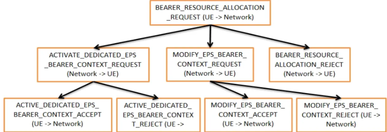
The dedicated EPS bearer establishment process is used to establish a dedicated EPS bearer between the UE and the P-GW. Dedicated bearer establishment may be initiated as a part of the attach process or separately. The bearer establishment is initiated by the network, but also the UE can request the process by sending a BEARER RESOURCE ALLOCATION REQUEST message towards the network and by starting the timer T3480. If no answer to the request is received before T3480 expires, the UE tries to resend the message. After four failed retransmissions, the process is declared failed. As the MME receives the BEARER RESOURCES ALLOCATION REQUEST message from the UE, it can either accept the request and respond with an ACTIVATE DEDICATED EPS BEARER CONTEXT REQUEST message (timer T3485 is started), reject the request and respond with a BEARER RESOURCE ALLOCATION REJECT message or request for a modification to the bearer parameters by responding with a MODIFY EPS BEARER CONTEXT REQUEST (timer T3486 is started). As the UE receives one of these three messages, it stops the timer T3480. If the UE accepts the context request, it responds
24
with an ACTIVATE DEDICATED EPS BEARER CONTEXT ACCEPT message or with a MODIFY EPS BEARER CONTEXT ACCEPT message, depending on the MME request type. The UE might also reject the context request by sending an ACTIVE DEDICATED EPS BEARER CONTEXT REJECT or a MODIFY EPS BEARER CONTEXT REJECT message towards the network. After the network receives the UE response, timer T3485/T3486 is stopped. Different variations of the dedicated EPS bearer establishment process are illustrated in figure 24. [25]
Figure 24. Different variations of the dedicated EPS bearer establishment process. 2.8.7 EPS Bearer Deactivation
The EPS bearer deactivation process is used to deactivate both default and dedicated EPS bearers. The process is initiated by the network, but also the UE might trigger it by requesting the deactivation. The deactivation signaling flow is illustrated in figure 25.
Figure 25. EPS bearer deactivation process.
1. The network sends a DEACTIVATE EPS BEARER CONTEXT REQUEST to the UE,
which includes a cause value indicating the reason for the deactivation. As the request is sent, the MME starts timer T3495. If the UE does not answer to the message before timer T3495 expires, the request is resent. The retransmission is repeated four times. After the fifth expiry, the MME deactivates the EPS bearer locally.
2. UE deletes the EPS bearer context and responds with a DEACTIVATE EPS BEARER CONTEXT ACCEPT message after receiving the deactivation request. The UE has no option of refusing the deactivation. When the MME receives the deactivation accept message, timer T3495 is stopped and the process is finished.
25 2.8.8 Intra-LTE Handover
The intra-LTE handover process can be divided into three main phases: handover preparation, handover execution and handover completion. The handover preparation phase is illustrated in figure 26 and the handover execution phase in figure 27. The signaling flow of the handover completion phase is omitted, since it does not have much significance in the scope of this thesis. In the handover preparation phase, the network is prepared for the handover and the required resources are reserved. In the handover execution phase, the UE is informed about the handover, packet forwarding is started and the UE connection/state is transferred to the target eNodeB. In the last phase, the handover completion, the DL data path is switched from the source eNodeB to the target eNodeB and the packet forwarding is stopped.
Figure 26. Intra-LTE handover preparation.
1. The eNodeB can specify different measurement reporting thresholds for the UEs with a MEASUREMENT CONTROL message. The measurement reporting can be either event based or periodic.
2. When the measurement reporting threshold is fulfilled, the UE sends a MEASUREMENTS REPORT message to the serving eNodeB. If the cell reselection condition is fulfilled, the handover process is initiated.
3. The source eNodeB makes a handover decision based on the contents of the MEASUREMENTS REPORT and cell reselection parameters.
4. The source eNodeB sends a HANDOVER REQUEST message to the target eNodeB. 5. Based on the amount of available resources, the admission control of the source cell decides if the incoming connection can be accepted. If the handover is accepted, target eNodeB reserves the necessary resources required for the connection.
26
Figure 27. Intra-LTE handover execution.
7. The source eNodeB sends a HANDOVER COMMAND message to the UE and starts forwarding the DL user data to the target eNodeB. This is a critical point in the handover process. If the UE receives the HANDOVER COMMAND successfully, there is no more need for a radio connection between the UE and the source eNodeB.
8. The source eNodeB prepares the target eNodeB for the handover by transferring the UE context to it. The target eNodeB starts to buffer the traffic forwarded by the source eNodeB.
9. The UE starts the handover expiry timer T304 and establishes the connection to the target eNodeB by using the random access process. After successfully connecting the target cell, the UE stops timer T304.
10. After the completion of the handover process, the UE sends a HANDOVER CONFIRM message to target eNodeB. [1] [21] [23]
27
Optimization of the Long Term Evolution
The LTE optimization process is a complex and demanding task, in which the effects of multiple factors to the network performance must be considered simultaneously. This chapter introduces some basic KPIs of LTE, reasons for high and low values for the particular KPIs, KPI measurement methods and the significance of the KPIs to the network performance and the user experienced QoS. In addition, corresponding KPIs in UMTS are presented.
3.1 Integrity KPIs
3.1.1 RSRP Level of the Best Available Cell
Description: RSRP level of the cell with the highest RSRP.
Reasons for a low RSRP level: Basically, RSRP level distribution is determined by the number of cells in the network. However, many other factors also have a significant effect to the RSRP levels, such as antenna tilts, transmitted RSRP levels, antenna heights, antenna azimuths and the propagation environment.
Effects of a low RSRP level: The RSRP level of the best available cell can be seen as an excellent KPI for the network coverage, which is a fundamental requirement for any wireless network. Inadequate coverage causes many problems, such as RLFs, handover failures, low throughput levels and service unavailability.
How to measure the KPI: In practice, the RSRP levels are measured using drive testing, in which a special scanner or an UE measures and saves the RSRP levels constantly. In addition, a GPS module is typically used to pinpoint the RSRP measurements to specific locations. However, with standardized messages it is also possible to instruct the UEs to report periodically the RSRP measurements to their serving eNodeBs. The problem in this approach is the pinpointing of the measurement to specific locations accurately enough. Some proposals for solving this problem have been made, such as the X-Map estimation [26], but so far no commercial products are available.
Corresponding KPI in UMTS: A corresponding KPI in UMTS is Received Signal Code Power (RSCP).
3.1.2 RSRQ Level of the Best Available Cell
Description: RSRQ level of the cell with the highest RSRQ.
Reasons for a low RSRQ level: RSRQ level is affected by three factors: RSRP level, DL interference level (RSSI) and noise level. However, in a typical interference limited LTE network, the significance of the noise is relatively small.
28
Effects of a low RSRQ level: RSRQ level represents DL signal quality of the network. Basically, an inadequate RSRQ level creates problems similar to an inadequate RSRP level.
How to measure the KPI: RSRP measurement methodologies apply also to RSRQ measurements (see section 3.1.1).
Corresponding KPI in UMTS: A corresponding KPI in UMTS is / , defined as the pilot signal energy of the Common Pilot Channel (CPICH) within one chip duration divided with the RSSI [27].
3.1.3 Number of RRC Connection Establishments and Active RRC Connections Description: The RRC connection establishment process is used to change the state of the UE from idle to connected, and thus enable the application level data exchange between the UE and the E-UTRAN [1].
Reasons for a low/high number of RRC connection establishment and active RRC connections: The number of RRC connection establishments and active RRC connections in a particular cell depends on the amount and behavior of users in the dominance area of the cell. For users utilizing data services constantly, the RRC connections remain active, even if the amount of sent data would be relatively small. If a majority of users behave similarly, the number of RRC connection establishments remains small, but the number of active RRC connections is high. On the other hand, for users having long pauses in their data utilization, the RRC connections are deactivated during the non-active periods and the user state is changed from connected to idle. Thus, in the next active period the RRC connection must be re-established via RRC connection establishment process. In a cell with a majority of users behaving this way, the number of RRC connection establishments is low and the number of active RRC connections high. In addition, the number of RRC connection establishment and the number of active RRC connections can be used to evaluate the balance of the network load. For example, a cell having significantly less RRC connection establishments and active RRC connections compared to the neighboring cells could indicate that the dominance area of the particular cell is too small. This can lead to a non-optimal network performance.
Effects of a low/high number of RRC connection establishment and active RRC connections: The RRC connection establishment process is based on the random access process, and therefore every connection establishment attempt consumes the random access resources. A high number of RRC connection establishments may cause delay in the random access process, random access failures and RRC connection establishment failures. In addition, eNodeBs have a limit for the maximum number of simultaneous active RRC connections. If the maximum number of RRC connections is
29
exceeded, part of the connection must be dropped [1] resulting in a degraded QoS for some users.
How to measure the KPI: The KPI can be either measured using drive testing or obtained from the network statistics.
Corresponding KPI in UMTS: Also in UMTS, UE resides either in RRC idle state or RRC connected state, and the transition from the idle state to the connected is done using the RRC connection establishment process. However, in UMTS the connected state has several substates, in which UE moves depending on its activity. [27]
3.1.4 Cell-Specific Load
Description: There are two main resources in LTE: transmission power and capacity. The cell-specific load can be defined either as the ratio between the number of allocated resource blocks and the total number of resource blocks [30] or as the ratio of the average transmission power and the total available transmission power.
Reasons for a high cell-specific load: The load is basically determined from the number of users in the cell and the service types users are requesting. In addition, the average radio conditions of the users have an effect on the resource usage of the provided services. For example, more resources must be allocated to the cell-edge users to provide a particular service than to the users near the eNodeB.
Effects of a high cell-specific load: When a cell is highly loaded, admission and congestion control of the cell will start to deny new connections, downgrade the quality of existing ones and possibly even drop out some of the connections. This can lead to handover failures, RRC connection rejects, increased number of RRC connection establishments, RLFs, low user-specific throughput and general degradation of user QoS.
How to measure the KPI: The cell-specific load can be obtained from the network statistics.
Corresponding KPI in UMTS: A similar KPI can be measured from UMTS network. However, due to the nature of the multiple access method of UMTS, the load is defined as the number of allocated codes rather than the number of allocated resource blocks.
3.1.5 Throughput
Description: The throughput of a particular user, a particular cell or the whole network.
Reasons for a low throughput: Low throughput can originate from multiple reasons. Low signal quality, high network load, terminal characteristics and subscription restrictions are the most typical reasons for low throughput levels. In addition, the
30
transmission towards the core network may be a bottleneck, cutting the throughput levels even though the radio interface could support higher throughputs. Furthermore, mobility related problems may cause degradation in the throughput. I should also be noted, that a low number of users or low data rate requirements of the users may cause a low throughputs in a cell/network level.
Effects of a low throughput: An adequate user-specific throughput is essential for the quality of any service and has an immediate effect on the user satisfaction. The cell/network-specific throughput is an important metric when evaluating the overall performance of the cell/network.
How to measure the KPI: User-specific throughput can be obtained either using drive testing or from the network statistics. Cell/network specific throughput can obtained only from the network statistics.
Corresponding KPI in UMTS: A similar KPI can be measured from UMTS network. 3.1.6 Modulation and Coding Scheme
Description: The utilized Modulation and Coding Scheme (MCS) in DL/UL.
Reasons for a utilization of low order MCSs: The utilized MCS is basically determined by the achievable SINR at the receiver end, which depends on the available transmit power, interference level, path loss and the magnitude of different hardware dependent gains and losses. In addition, mobility related problems can have a significant impact to the achievable SINR resulting in high proportion of low order MCS samples. Furthermore, the utilization of 64-Quadrature Amplitude Modulation (QAM) may be restricted without an additional license bought from the vendor. By enabling the support of the high order modulation schemes, the high SINRs can be utilized more effectively resulting in higher throughput levels.
Effects of the utilized MCS: The utilized MCS has a direct impact to the throughput both in UL and DL. The achievable throughputs may be very modest with the low order modulations and coding rates. In contrast, with more complex modulation schemes and higher coding rates, much higher throughput levels can be reached.
How to measure the KPI: The MCS distribution can be either measured using drive testing or obtained from the network statistics.
Corresponding KPI in UMTS: Adaptive MCS selection is utilized also in UMTS and has similar effects than in LTE.
3.1.7 User Plane Latency
Description: The user plane latency is typically measured as a Round Trip Time (RTT), defined as the time it takes for an IP packet to travel from the UE to a server in the PDN and back.