NASA
Technical
Memorandum
4574
Static
Investigation
of Two
Fluidic
Thrust-Vectoring
Concepts
on a
Two-Dimensional
Convergent-Divergent
Nozzle
David
]. Wing
Langley
Research
Center
• Hampton,
Virginia
National
Aeronautics
and Space
Administration
NASA Center for AeroSpace Information 800 Elkridge Landing Road
Linthicum Heights, MD 21090-2934 (301) 621-0390
National Technical Information Service (NTIS) 5285 Port Royal Road
Springfield, VA 22161-2171 (703) 487-4650
A static
investigation
was
conducted
in the
static
test
facility
of the
Langley
16-Foot
_i'ransonie
Tun-nel
of
two
thrust-vectoring
concepts
which
utilize
fluidic
mechanisms
for
deflecting
the
jet
of
a
two-dimensional
convergent-divergent
nozzle.
One
con-cept. involved
using
the
Coanda
effect
to turn
a sheet
of injected
secondary
air
along
a curved
sidewall
flap
and,
through
entrainment,
draw
the
primary
jet
in
the
same
direction
to produce
yaw
thrust
vectoring.
The
other
concept
involved
deflecting
the
primary
jet
to
produce
pitch
thrust
vectoring
by
injecting
sec-ondary
air
through
a |.ransverse
slot
in the
divergent
flap,
creating
an oblique
shock
in the
divergent
chan-nel.
Geometric
variables
included
nozzle
expansion
ratio,
Coanda
sidewall
flap
angles,
and
injection
slot
longitudinal
location.
Fluidic
variables
included
noz-zle pressure
ratio
fi'om
2 to 10 and
secondary
weight
flow from
0 to 10 percent
of the
primary
weight
flow.
Utilizing
the
Coanda
effect
to produce
yaw
thrust
w,ctoring
was
largely
mlsuccessflfl.
Small
vector
an-gh!s were
produced
at low primary
nozzle
pressure
ra-t.ios, probably
because
the
momentun_
of tile primary
jet
was
low.
The
aspect
ratio
of the
nozzle
used
in
the
investigation
may
have
hindered
the
production
of significant
vector
angles.
Significant
pitch
thrust
vector
angles
were
pro-duced
by injecting
secondary
flow
through
a slot
in
the
divergent
flap.
Thrust
vector
angle
decreased
with
increasing
nozzle
pressure
ratio
but
moderate
levels
were
maintained
at.
the
highest
nozzle
pres-sure
ratio
tested.
Control
of thrust
vector
angle
was
achieved
by wtrying
the
secondary-to-primary
weight
flow
ratio.
Linearity
of this
control
was
improved
by
moving
the
slot
location
aft.
hnpingement
of
the
oblique
shock
on the
opposite
flap
occurred
for
com-binations
of low expansion
ratio
and
forward
slot.
in-jection
location,
and
the
effect
was
to reduce
pitch
thrust
vectoring.
Thrust
performance
generally
in-creased
at
low
nozzle
pressure
ratios
and
decreased
near
tile
design
pressure
ratio
with
the
addition
of
secondary
flow.
Introduction
Exhaust
nozzles
with
the
capability
to
redirect
the
resultant,
thrust
of
an
engine
from
the
aircraft
longitudinal
axis
will
greatly
increase
the
versatility
and
maneuverability
of fighter
aircraft
(refs.
1 and
2).
This
improvement
in capability
is accomplished
by
providing
a means
for controlling
the aircraft
attitude
in flight
regimes
where
conventional
flight
controls
are
less
effective.
These
regimes
include
low-speed
flight,
where
dynamic
pressure
is low, and
high-angle-of-attack
flight,
where
flow separation
from
the
wings
surfaces,
rendering
them
less effective.
With
the
use
of thrust
vectoring,
attitude
control
in the
form
of
engine
power
would
be
readily
available
to the
pilot
through
a greater
range
of airspeeds
and
attitudes.
The
design
of high-performance
thrust-vectoring
exhaust
nozzles,
however,
must
consider
other
con-straints
as
well,
including
weight,
systems
com-plexity,
and
observability.
Many
thrust-vectoring
concepts
work
against
these
design
considerations
because
they
usually
depend
upon
the
use
of
vari-able
geometry,
or movable
hardware.
The
actuators
associated
with
variable
geometry
add
to the
aircraft
weight
and
complexity.
These
adverse
factors
and
the
quest
for low observability
have
led designers
to
(:oil-sider
fixed-aperture
nozzles,
those
with
a fixed
exit
plane
and
ideally
no externally
moving
parts.
Fluidic
concepts
can potentially
provide
a
thrust-vectoring
capability
to
fixed-aperture
nozzles.
The
concept
of
fluidic
thrust
vectoring
is to
deflect
the
thrust
of the
jet
by
using
the
influence
of a second
smaller
exhaust
streain.
This
secondary
flow
would
typically
be
injected
into
or
near
the
primary
jet.
stream
and
would
require
few,
if any,
moving
parts.
Nozzle
weight
and
complexity
could
therefore
be
reduced.
Tile
secondary
flow
may
also
be
used
to
provide
cooling
to nozzle
surfaces.
An
experiinental
investigation
was
conducted
of
two fluidic
thrust-vectoring
concepts
on the
dual-flow
propulsion
simulation
syst.em
in the
static
test
facil-it.y of
the
Langley
16-Foot
Transonic
Tunnel.
The
two
concepts
were
evaluated
on
a
two-dimensional
convergent-diw,
rgent
nozzle.
The
first
concept
uti-lized
the
Coanda
effect
in
conjunction
with
a
sec-omtary
flow
stream
to turn
the
jet.
The
Coanda
ef-fect
(ref.
3) is the
tendency
for a fluid
to follow
the
convex
curvature
of a solid
boundary.
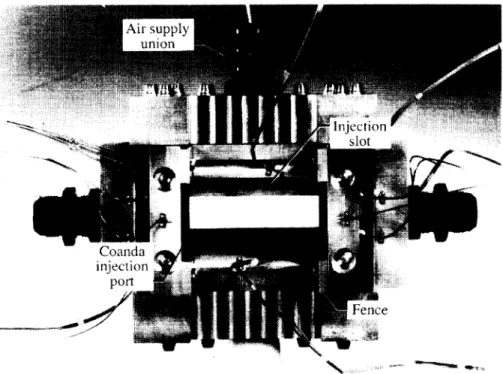
Secondary
flow
was injected
along
the
sidewall
of the
nozzle
as a
ver-tical
sheet
parallel
to the
primary
jet and
adjacent
to
a sidewall
flap
with
convex
curvature.
As a result
of
the
Coanda
effect,
it was
believed
that
the
injected
flow
would
turn
outward
with
the
convex
wall
and,
through
entrainment,
would
deflect
the
primary
jet in
the
same
direction
to produce
yaw
thrust
vectoring.
Parameters
varied
for the
test
of this
concept
include
the
nozzle
expansion
ratio,
the
Coanda
flap
(convex
sidewall)
deflection
angle,
the
Coanda
flap
length,
the
secondary
flow
rate
relative
to the
primary
flow
rate,
and
the
primary
nozzle
pressure
ratio.
The
second
concept
utilized
the
injection
of a
lat-eral
sheet
of secondary
flow
directly
into
the
super-sonic
primary
exhaust
through
a
spanwise
slot
in
tile
divergent
flap.
The
injection
would
present
an
obstructiontothesupersonic
flow,causinganoblique
shockto form upstreamof the slot, which would
deflectthe primaryjet awayfrom the slottedflap.
Parametersvariedfor the test of this
conceptin-cludenozzleexpansion
ratio,injectionslotaxialloca-tion, the secondary
flowrate relativeto the primary
flow rate, and the primary nozzlepressureratio.
Either fluidic thrust-vectoringconceptcouldbe
in-corporatedindividuallyinto a nozzledesignto
pro-ducesingle-axisthrust vectoring,or both concepts
couldbe combinedto
producemultiaxisthrustvec-toring.
Combined
performance
will
not
be discussed
here,
although
some
such
data
were
acquired
and
are
tabulated
in this
report.
The
nozzles
were
tested
at
static
conditions
(jet
flow
only,
no external
flow).
A single
nozzle
model
was built
to test
both
concepts.
Primary
nozzle
pres-sure
ratio
was
varied
from
2 to 10. The
percentage
of
secondary
to primary
weight
flow
was
varied
from
0
to
10 percent.
Data
acquired
included
force
and
moment
measurements,
internal
static
pressure
mea-surements,
and
limited
flow
visualization
including
paint
flow
and
schlieren
photography.
Symbols
At
Fa
F_
f i,p 12i,siF_
nozzle
throat
area,
in 2
thrust
measured
along
nozzle
axis,
lbf
total
ideal
isentropic
thrust,
lbf,
Fi,p + Fi,c + Fi,si
ideal
isentropic
thrust
of left
and
right
Coanda
ports,
lbf,
Wc
_'
_f_l
1-\Pt,c/
j
ideal
isentropic
thrust
of primary
jet,
lbf,
Wp
7
\ Pt,j /
J
ideal
isentropic
thrust
of injection
slot,
lbf,
IRjrtsi 2_ [1_( pa I ('y-I_/?]
Wsi g-if' "/_-- 1 \ Pt,si / J
measured
jet
normal
force,
lbf
gross
resultant
thrust,
lbf,
measured
jet
side
force,
lbf
LI
NPR
(NPR)des
P
Pa
Pt,c
Pt,j
Pt,si
R
Rj
T_c Wc Wiwp
Wsi Xc X8 xtmeasured
along
nozzle
axis
from
forward
end
of flap
to divergent
surface
trailing
edge
(fig.
6(c)),
in.
nozzle
pressure
ratio,
Pt,j/Pa
design
nozzle
pressure
ratio
local
internal
static
pressure,
psia
atmospheric
pressure,
psia
average
Coanda
secondary
flow
total
pressure,
psia
average
primary
jet
total
pressure,
psia
slot
injection
secondary
flow total
pressure,
psia
Coanda
flap
radius,
0.500
in.
gas
constant
(for y =
1.3997),
1716
ft2/sec2-°R
average
Coanda
secondary
flow
total
temperature,
°R
average
primary
jet
total
temperature,
°R
slot
injection
secondary
flow total
temperature,
°R
sum
of left
and
right
side
measured
weight
flow
rate
of Coanda
secondary
flow,
lbf/sec
ideal
primary
weight
flow rate,
choked
nozzle,
lbf/sec,
Vr j
measured
primary
weight
flow
rate,
lbf/sec
measured
weight
flow
rate
of slot
injection
secondary
flow,
lbf/sec
axial
distance
measured
aft
from
for-ward
surface
of lower
flap
(fig.
7), in.
curvilinear
distance
along
Coanda
flap,
positive
downstream
from
inter-section
of curved
and
planar
surfaces
(fig.
7), in.
axial
distance
from
forward
end
of upper
flap
to injection
slot
(fig.
6(c)),
in.
axial
distance
from
forward
end
of
upper
or lower
flap
to nozzle
throat
right
edge
of upper
flap
(fig.
7), in.
Yt
width
of nozzle
at
throat
(fig.
6(c)),
3.983
in.
z,_
vertical
distance
from
outside
surface
of divergent
flap
to divergent
channel
trailing
edge
at nozzle
exit
(fig. 6(c)),
in.
z/,
vertical
distance
front
top
surface
of
upt)er
flap
to center
of cylindrical
plenuin
for
injection
slot
(fig.
6(c)),
in.
(_
angle
of injection
slot. measured
with
respect
to vertical,
positive
inclination
toward
nozzle
exit
(fig.
6((:)),
dog
.3s
angh'
of injection-slot
plenum
supply
ducts
in upper
flap
measured
with
respect
to vertical
(tig.
6(c)),
deg
7
ratio
of specific
heats,
1.3997
for air
@
pitch
thrust
vector
angle,
(leg,
tan-
1(FT,/Fo)
G,,p
jet
centerlinc
deflection
angle
as a
result
of asymmetric
upper
and
lower
flaps,
positive
down,
(leg, (0 / - 0,,)/2
_._/
yaw
thrust
vector
angle,
deg,
tan-
t (Fs//_,)
Exit
area
g
nozzle
expansion
ratio,
Throat
area
0 l
divergence
angle
of lower
flap,
positive
away
from
nozzle
axis,
deg
0,,
divergence
angle
of upper
flap,
positive
away
froln
nozzle
axis,
deg
cOl
left
Coanda
flap
angle
measured
with
respect
to nozzle
axis,
positive
away
from
priinary
jet,
(leg
cOt
right
Coanda
flap
angle
measured
with
respect
to nozzle
axis,
positive
away" from
priinary
jet,
(leg
corrected
weight
flow
ratio
of combined
w_ v/T_7,_
left
and
right
Coanda
ports,
wv x/T_,a
corrected
weight
flow
ratio
of slot
Wsi