C H A P T E R
3
Cables and Connectors
This chapter describes the I/O interfaces, the data cables, and power cordsets required in using the LS2020 enterprise ATM switch. These facilities are described in the following order:
•
Low-speed connectors and data cables for X.21, RS-449, and V.35 serial interfaces.•
Circuit emulation access card (CEMAC) connectors and data cables for 75-ohm and 120-ohm interfaces.•
Medium-speed connectors and data cables for the 2-port access card, the 4-port T3/E3 access card, and the 8-port T3/E3 access card.•
OC-3c connectors and data cables•
FDDI connectors and data cables•
Ethernet connectors and data cables•
Fiber Ethernet access card (FEAC) connectors and data cables•
Console and modem connectors and data cables•
Country kits and power cordsetsSignal diagrams are provided for each I/O connector and data cable.
For most cables, two part numbers are provided in an associated table in the body of the chapter: the manufacturing number (which appears on the cable itself); and the order number (which is used in ordering the cable from Cisco Systems). Cables without associated order numbers are not available from Cisco Systems; such cables are widely available from other vendors as standard items.
Cable Drawing Conventions
Figure 3-1 shows the conventions used in representing the signal paths in the LS2020 I/O interface connectors and data cables illustrated in this chapter.
3-2 LightStream 2020 Site Planning and Cabling Guide Low-Speed Connectors and Data Cables
Figure 3-1 LS2020 Cable Signal Diagram Conventions
Low-Speed Connectors and Data Cables
This section presents the specifications for the connectors and data cables for the low-speed X.21, RS-449, and V.35 serial I/O interfaces of the LS2020 switch. This information is presented as follows:
•
X.21 fantail connector - see the section “X.21 Fantail Connector.”•
RS-449 fantail connector - see the section “RS-449 Fantail Connector.”•
V.35 fantail connector - see the section “V.35 Fantail Connector.”•
DSU/CSU control ports on V.35 and RS-449 fantails - see the section “DSU/CSU Control Port Connector.”•
Internal data cable for connecting a low-speed access card to a fantail - see the section “Low-Speed Access Card Fantail Cable.”•
Data cable for connecting an X.21 fantail to an external X.21 device - see the section “X.21 Interface Cable.”•
Data cable for connecting an RS-449 fantail to an external RS-449 DCE device - see the section “RS-449 Interface Straight-Through Cable.”•
Data cable for connecting two LS2020 switches via their RS-449 fantail interfaces, or for connecting an RS-449 fantail to an external RS-449 DTE device - see the section “RS-449 Interface Crossover Cable.”•
Data cable for connecting a V.35 fantail to an external V.35 DCE device - see the section “V.35 Interface Straight-Through Cable.”•
Data cable for connecting two LS2020 switches via their V.35 fantail interfaces, or for connecting a V.35 fantail to an external V.35 DTE device - see the section “V.35 Interface Crossover Cable.”X.21 Fantail Connector
Figure 3-2 shows the pin assignments of the X.21 fantail connector. Interface connector type: DB15 female
Connectors per fantail: 8 (numbered 0 - 7)
Cable wire
Signal ground wire Protective ground wire
Cable wire that is part of a twisted pair
Low-Speed Connectors and Data Cables
Figure 3-2 X.21 Connector Pin Assignments
RS-449 Fantail Connector
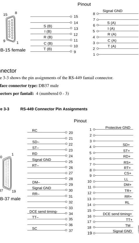
Figure 3-3 shows the pin assignments of the RS-449 fantail connector. Interface connector type: DB37 male
Connectors per fantail: 4 (numbered 0 - 3)
Figure 3-3 RS-449 Connector Pin Assignments
Pinout 8 7 6 5 4 3 2 1 14 13 12 11 10 9 C (B) I (B) T (B) S (B) DB-15 female H3387 R (B) T (A) C (A) R (A) I (A) S (A) Signal GND 1 8 9 15 15 Pinout 1 2 3 4 SD+ Protective GND 5 6 7 8 RS+ RT+ RD+ 9 10 11 12 DM+ TR+ LL 13 14 15
16 DCE send timing+ RL 17 18 19 TM Signal GND TT+ 20 21 22 23 24 25 26 27 28 29 30 31 32 33 34 35 36 37 SD– ST– RT– RR– DM– TT– SC ST+ RR+ RC RD Signal GND Signal GND
DCE send
timing-H3388 DB-37 male 1 19 20 37 CS+
3-4 LightStream 2020 Site Planning and Cabling Guide Low-Speed Connectors and Data Cables
V.35 Fantail Connector
Figure 3-4 shows the pin assignments of the V.35 fantail connector. Interface connector type: ISO 2593 male (34-pin block type) Connectors per fantail: 4 (numbered 0 - 3)
Figure 3-4 V.35 Connector Pin Assignments
DSU/CSU Control Port Connector
The RS-232 DSU/CSU connector appears on both the V.35 and RS-449 fantails. If you connect the control port to the craft port on a DSU/CSU device, you can use the csumon program to
communicate with the DSU/CSU from an LS2020 switch. Interface connector type: DB9 male
Connectors per fantail: 4 (numbered 0 - 3)
Figure 3-5 shows the pin assignments of the RS-232 DSU/CSU control port connector.
Figure 3-5 RS-232 DSU/CSU Control Port Pin Assignments
Pinout B D F J L N R T LL RT+ DCEST– DCD Signal GND RD+ RD– RL RT– V X Z DD JJ LL NN DCEST+ TM BB FF A C E H K M P DSR DTR RTS S U W AA EE HH KK Y CC MM SD+ SD-TT+ TT-ST+ ST-Protective GND H3389 ISO 2593 male B NN C KK CTS Pinout 1 2 3 4 5 6 7 8 9 Signal GND RD TD H3390 DB-9 male 1 5 6 9
Low-Speed Connectors and Data Cables
Low-Speed Access Card Fantail Cable
This 100-pin data cable is used as the means of interconnection between the bulkhead connector of a low-speed X.21, RS-449, or V.35 access card and the back of the fantail.
The cable is available from Cisco Systems in three lengths. For ordering purposes, use the appropriate order number from the table below.
Note that two such data cables are required to connect one X.21 fantail to a low-speed access card, while one only such cable is required to connect each V.35 or RS-449 fantail to a low-speed access card.
X.21 Interface Cable
This cable is used to connect the X.21 fantail connector to an external X.21 device. The cable is available from Cisco Systems in three lengths. For ordering purposes, use the appropriate order number from the table below.
Note Use the switches on the X.21 fantail to select a DTE or DCE interface for each port.
Figure 3-6 is a signal diagram for the X.21 fantail cable. Manufacturing No. Length Order No.
72-1117-01 4 feet L2020-CAB-F4=
72-1118-01 8 feet L2020-CAB-F8=
72-1119-01 12 feet L2020-CAB-F12=
Manufacturing No. Length Order No.
72-0991-01 30 feet LS-CAB-X21-TC30=
72-0992-01 50 feet LS-CAB-X21-TC50=
3-6 LightStream 2020 Site Planning and Cabling Guide Low-Speed Connectors and Data Cables
Figure 3-6 X.21 Cable Signal Diagram
RS-449 Interface Straight-Through Cable
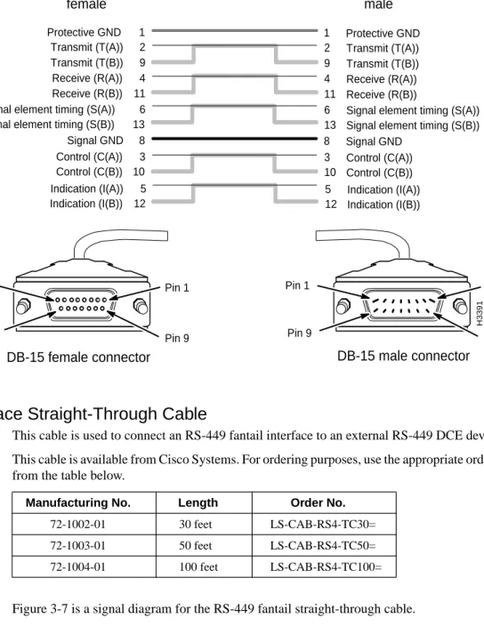
This cable is used to connect an RS-449 fantail interface to an external RS-449 DCE device. This cable is available from Cisco Systems. For ordering purposes, use the appropriate order number from the table below.
Figure 3-7 is a signal diagram for the RS-449 fantail straight-through cable. Manufacturing No. Length Order No.
72-1002-01 30 feet LS-CAB-RS4-TC30= 72-1003-01 50 feet LS-CAB-RS4-TC50= 72-1004-01 100 feet LS-CAB-RS4-TC100= 6 11 4 9 2 Transmit (T(A)) Receive (R(B)) Signal element timing (S(A))
Receive (R(A)) Transmit (T(B)) 10 3 13 Control (C(A)) Signal element timing (S(B))
Control (C(B)) 6 11 4 9 2 10 3 13 Transmit (T(A)) Receive (R(B))
Signal element timing (S(A)) Receive (R(A))
Transmit (T(B))
Control (C(A))
Signal element timing (S(B))
Control (C(B))
DTE end DCE end
female male DB-15 female connector Pin 1 Pin 9 Pin 8 Pin 15 Pin 1 Pin 9 Pin 8 Pin 15 DB-15 male connector 5 Indication (I(A)) 12 Indication (I(B)) 5 12 Indication (I(A)) Indication (I(B)) 1 Protective GND 1 Protective GND 8 Signal GND 8 Signal GND H3391
Low-Speed Connectors and Data Cables
Figure 3-7 RS-449 Straight-through Cables Signal Diagram
15 34 16 35 17 36 18 37 19
LightStream DTE end DCE end
Terminal Timing (TT+) Send Common (SC) Signal Ground (SG)
StandBy indicator (SB) Test Mode (TM)
DCE Send Timing- (NS) Incoming Call (IC) DCE Send Timing+ (SR/SF)
Terminal Timing (TT–) 29 11 30 12 31 13 32 14 33 Receiver Ready (RR–) Remote Loopback (RL) Signal Quality (SQ) Receiver Ready (RR+) Select Standby (SS) Data Mode (DM+) Data Mode (DM–) Signal Ground (TR–) Terminal Ready (TR+) 6 25 7 26 8 27 9 28 10 Receive Timing (RT+) terminal In Service (IS) Local Loopback (LL) Clear to Send (CS–) Clear to Send (CS+) Signal Ground (RS–) Receive Data (RD+) Request to Send (RS+) Receive Timing (RT–) 20 2 21 3 22 4 23 5 24 Send Data (SD–) Send Timing (ST+) Receive Data (RD–) Send Data (SD+) Send Timing (ST–)
Signalling rate Indicator (SI) SPARE SPARE Receive Common (RC) 1 Protective Ground (PG) 15 34 16 35 17 36 18 37 19 29 11 30 12 31 13 32 14 33 6 25 7 26 8 27 9 28 10 20 2 21 3 22 4 23 5 24 1 Terminal Timing (TT+) Send Common (SC) Signal Ground (SG) StandBy indicator (SB) Test Mode (TM)
DCE Send Timing– (NS) Incoming Call (IC)
DCE Send Timing+ (SR/SF) Terminal Timing (TT–) Receiver Ready (RR–) Remote Loopback (RL) Signal Quality (SQ) Receiver Ready (RR+) Select Standby (SS) Data Mode (DM+) Data Mode (DM–) Signal Ground (TR–) Terminal Ready (TR+) Receive Timing (RT+) terminal In Service (IS) Local Loopback (LL) Clear to Send (CS–) Clear to Send (CS+) Signal Ground (RS–) Receive Data (RD+) Request to Send (RS+) Receive Timing (RT–) Send Data (SD–) Send Timing (ST+) Receive Data (RD–) Send Data (SD+) Send Timing (ST–)
Signalling rate Indicator (SI) SPARE
SPARE
Receive Common (RC) Protective Ground (PG)
DB-37 female connector DB-37 male connector
Pin 1 Pin 20 Pin 19 Pin 1 Pin 1 Pin 20 Pin 19 Pin 37 female male H3392
3-8 LightStream 2020 Site Planning and Cabling Guide Low-Speed Connectors and Data Cables
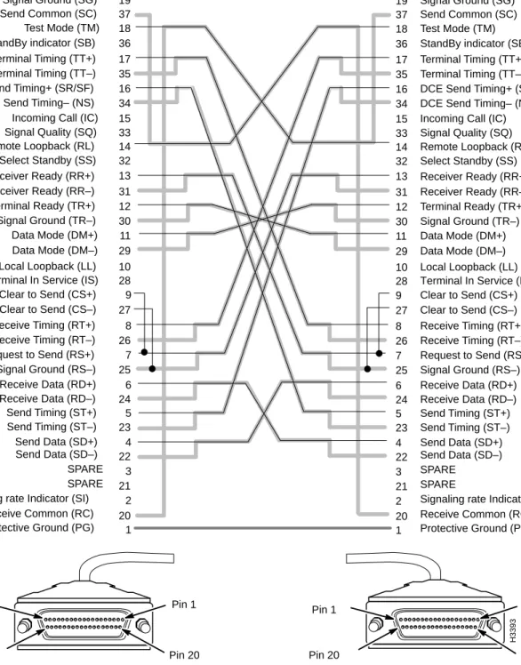
RS-449 Interface Crossover Cable
This cable is used to connect two LS2020 switches via their RS-449 fantail interfaces, or to connect an RS-449 fantail interface to an external RS-449 DTE device.
The cable is available from Cisco Systems. For ordering purposes, use an appropriate order number from the table below.
Figure 3-8 is a signal diagram for the RS-449 fantail crossover cable. Manufacturing No. Length Order No.
72-1008-01 8 feet LS-CAB-RS4-TT8=
72-1005-01 30 feet LS-CAB-RS4-TT30=
72-1006-01 50 feet LS-CAB-RS4-TT50=
Low-Speed Connectors and Data Cables
Figure 3-8 RS-449 Crossover Cable Signal Diagram
15 34 16 35 17 36 18 37 19
LightStream DTE end DTE end
Terminal Timing (TT+) Send Common (SC) Signal Ground (SG)
StandBy indicator (SB) Test Mode (TM)
DCE Send Timing– (NS) Incoming Call (IC) DCE Send Timing+ (SR/SF)
Terminal Timing (TT–) 29 11 30 12 31 13 32 14 33 Receiver Ready (RR–) Remote Loopback (RL) Signal Quality (SQ) Receiver Ready (RR+) Select Standby (SS) Data Mode (DM+) Data Mode (DM–) Signal Ground (TR–) Terminal Ready (TR+) 6 25 7 26 8 27 9 28 10 Receive Timing (RT+) Terminal In Service (IS)
Local Loopback (LL) Clear to Send (CS–) Clear to Send (CS+) Signal Ground (RS–) Receive Data (RD+) Request to Send (RS+) Receive Timing (RT–) 20 2 21 3 22 4 23 5 24 Send Data (SD–) Send Timing (ST+) Receive Data (RD–) Send Data (SD+) Send Timing (ST–)
Signaling rate Indicator (SI) SPARE SPARE Receive Common (RC) 1 Protective Ground (PG) 15 34 16 35 17 36 18 37 19 29 11 30 12 31 13 32 14 33 6 25 7 26 8 27 9 28 10 20 2 21 3 22 4 23 5 24 1 Terminal Timing (TT+) Send Common (SC) Signal Ground (SG) StandBy indicator (SB) Test Mode (TM)
DCE Send Timing– (NS) Incoming Call (IC)
DCE Send Timing+ (SR/SF) Terminal Timing (TT–) Receiver Ready (RR–) Remote Loopback (RL) Signal Quality (SQ) Receiver Ready (RR+) Select Standby (SS) Data Mode (DM+) Data Mode (DM–) Signal Ground (TR–) Terminal Ready (TR+) Receive Timing (RT+) Terminal In Service (IS) Local Loopback (LL) Clear to Send (CS–) Clear to Send (CS+) Signal Ground (RS–) Receive Data (RD+) Request to Send (RS+) Receive Timing (RT–) Send Data (SD–) Send Timing (ST+) Receive Data (RD–) Send Data (SD+) Send Timing (ST–)
Signaling rate Indicator (SI) SPARE
SPARE
Receive Common (RC) Protective Ground (PG)
DB-37 female connector DB-37 male connector
Pin 1 Pin 20 Pin 19 Pin 37 Pin 1 Pin 20 Pin 19 Pin 37 female female H3393
3-10 LightStream 2020 Site Planning and Cabling Guide Low-Speed Connectors and Data Cables
V.35 Interface Straight-Through Cable
This cable is used to connect a V.35 fantail interface to an external V.35 DCE device.
The cable is available from Cisco Systems. For ordering purposes, use an appropriate order number from the table below.
Figure 3-9 is a signal diagram for the V.35 fantail straight-through cable. Manufacturing No. Length Order No.
72-1009-01 30 feet LS-CAB-V35-TC30=
72-1010-01 50 feet LS-CAB-V35-TC50=
Low-Speed Connectors and Data Cables
Figure 3-9 V.35 Straight-through Cable Signal Diagram
K J H F E D C B A
Data Set Ready (DSR) Signal Ground (SG) Protective Ground (PG)
Clear To Send (CTS) Request To Send (RTS)
Ring Indicator (RI) LTST (Cisco 4000) Data Terminal Ready (DTR)
Data Carrier Detect (DCD)
V U T S R P N M L Receive Data RD+) Local Loopback (LL) Send Data (SD+) Remote Loopback (RL) Terminal Timing (TT+) Receive Timing (RT+) Receive Data (RD–) Send Data (SD+) EE DD CC BB AA Z Y X W Send Timing (ST–) Receive Timing (RT–) Terminal Timing (TT–) Send Timing (ST+) NN MM LL KK JJ HH FF
DCE Send Timing+ DCE DSR (T300) DCE Send Timing–
Test Mode (TN) K J H F E D C B A V U T S R P N M L EE DD CC BB AA Z Y X W NN MM LL KK JJ HH FF
Data Set Ready (DSR) Signal Ground (SG) Protective Ground (PG)
Clear To Send (CTS) Request To Send (RTS)
Ring Indicator (RI) LTST (Cisco 4000)
Data Terminal Ready (DTR) Data Carrier Detect (DCD)
Receive Data RD+) Local Loopback (LL) Send Data (SD+) Remote Loopback (RL) Terminal Timing (TT+) Receive Timing (RT+) Receive Data (RD–) Send Data (SD–) Send Timing (ST–) Receive Timing (RT–) Terminal Timing (TT–) Send Timing (ST+)
DCE Send Timing+ DCE DSR (T300) DCE Send Timing–
Test Mode (TN) Pin C Pin D Pin A Pin B Pin C Pin D Pin A Pin B
34-position female block connector 34-position male block connector LightStream DTE end DCE end
female male
3-12 LightStream 2020 Site Planning and Cabling Guide Low-Speed Connectors and Data Cables
V.35 Interface Crossover Cable
This cable is used to connect two LS2020 switches via their V.35 fantail interfaces, or to connect a V.35 fantail to an external V.35 DTE device.
This cable is available from Cisco Systems. For ordering purposes, use the appropriate order number from the table below.
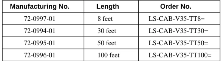
Figure 3-10 is a signal diagram for the V.35 fantail crossover cable. Manufacturing No. Length Order No.
72-0997-01 8 feet LS-CAB-V35-TT8=
72-0994-01 30 feet LS-CAB-V35-TT30=
72-0995-01 50 feet LS-CAB-V35-TT50=
Low-Speed Connectors and Data Cables
Figure 3-10 V.35 Crossover Cable Signal Diagram
M L F H J E D C B A Y X W V U T S R P N Receive Data A (RD A) Data Terminal Ready (DTR)
Terminal Timing A (TT A)
Send Timing A (ST A) Data Carrier Detect (DCD)
Data Set Ready (DSR)
Request To Send (RTS) Receive Data B (RD B) Send Data A (SD A) Z AA BB CC DD EE FF HH JJ KK LL MM NN L D C J E H F B A LL W X U V S T P R NN M Z JJ BB CC DD EE FF HH AA KK Y MM N Send Data B (SD B) Receive Timing B (RT B)
DCE Send Timing B (DCEST B)
Remote Loopback (RL) Data Terminal Ready (DTR)
Data Carrier Detect (DCD)
Terminal Timing A (TT A)
Send Timing B (ST B) Signal Ground (SG)
Data Set Ready (DSR) Request To Send (RTS) Receive Data A (RD A) Send Data A (SD A) Receive Data B (RD B) Send Data B (SD B) Receive Timing B (RT B) Send Timing A (ST A) Terminal Timing B (TT B) Terminal Timing B (TT B) Receive Timing A (RT A) Receive Timing A (RT A) Local Loopback (LL) K K
DCE Send Timing A (DCEST A)
Send Timing B (ST B) DCE Send Timing B (DCEST B)
Test Mode (TM) DCE Send Timing A (DCEST A)
Pin C Pin D Pin A Pin B Pin C Pin D Pin A Pin B
34-position female block connector 34-position female block connector
Protective Ground (PG) Protective Ground (PG)
Local Loopback (LL) Test Mode (TM) Remote Loopback (RL) Female Female H3395 Signal Ground (SG)
3-14 LightStream 2020 Site Planning and Cabling Guide
Circuit Emulation Access Card (CEMAC) Connectors and Cables
Circuit Emulation Access Card (CEMAC) Connectors and Cables
Figure 3-11 shows the CEMAC card and its associated data cable. To make a more secureconnection, unscrew the top mounting screw (shown as “1” in the figure) in the connector retention bracket and reposition it in the connector (as shown by “2” in the figure). Next, tighten down the mounting screw to attach the data cable to the CEMAC card securely (as shown by “3” in the figure). Finally, secure the cable to the CEMAC bulkhead connector with the Velcro strip.
Circuit Emulation Access Card (CEMAC) Connectors and Cables
Figure 3-11 CEMAC Access Card and Data Cable Connection
E2 E6 E1 0 E14 75 120 75 120 75 120 75 120 75 120 75 120 75 120 75 120 E1 8 E22 E26 E30 GND E1 C21 E17 U1 E1 CEMAC 2 E2 E6 E1 0 E14 75 120 75 120 75 120 75 120 75 120 75 120 75 120 75 120 E1 8 E22 E26 E30 GND E1 C21 E17 U1 E1 CEMAC H3618 1 Secure cable with Velcro strip Add optional cable tie Seat cable firmly in bulkhead connector 3
3-16 LightStream 2020 Site Planning and Cabling Guide
Circuit Emulation Access Card (CEMAC) Connectors and Cables
Table 3-1 shows the pinout assignments of the CEMAC access card connector.
CEMAC Fantail
Figure 3-12 shows the E1 fantail for 75-ohm CEMAC applications. For convenience, Figure 3-12 illustrates both the BNC and SMZ connector types that can be used in the E1 fantail.
Figure 3-12 E1 Fantail (75-ohm)
Refer to the LightStream 2020 Hardware Reference and Troubleshooting Guide for information regarding the configuration of the TX GND and RX GND jumpers on the E1 fantail.
Table 3-1 CEMAC Bulkhead Connector Pinout Assignments
Receive Transmit
Port Tip Ring Tip Ring
0 26 1 39 14 1 27 2 40 15 2 28 3 41 16 3 29 4 42 17 4 30 5 43 18 5 31 6 44 19 6 32 7 45 20 7 33 8 46 21 Not used 34 9 47 22 Not used 35 10 48 23 Not used 36 11 49 24 Not used 37 12 50 25
Note: The information in this table is an extraction from Figure 10 of American National Standard T1.403-1989. H3632 RXO RX1 TXO TX1 RX2 RX3 TX2 TX3 RX4 RX5 TX4 TX5 RX6 RX7 TX6 TX7 RX8 RX9 TX8 TX9 RX10 RX11 TX10 TX11 E1 FANTAIL RX GND TX GND BNC connectors SMZ connectors
Medium Speed Connectors and Cables
E1 Fantail Data Cable
This 50-pin cable is used as the means of interconnection between the 8-port bulkhead connectors on the CEMAC card and the back of the E1 fantail. Figure 3-13 illustrates this cable.
The cable is available from Cisco Systems in three lengths. For ordering purposes, use the appropriate order number from the table below.
Figure 3-13 E1 Fantail Data Cable
Medium Speed Connectors and Cables
This section describes the connectors and cables for the medium-speed (2-port) access card, as well as the T3 and E3 (4-port and 8-port) access cards, as indicated below:
•
External connectors on the medium-speed (2-port) access card - see Figure 3-14.•
External connectors on the T3 and E3 (4-port and 8-port) access cards - see Figure 3-15.Manufacturing No. Length Order No.
72-1094-01 4 feet LS-CAB-8E1-4B=
72-1095-01 8 feet LS-CAB-8E1-8B=
72-1096-01 12 feet LS-CAB-8E1-12B=
3-18 LightStream 2020 Site Planning and Cabling Guide Medium Speed Connectors and Cables
Connectors on Medium-speed Access Card
Interface connector type: 75 ohm BNC jacks
Connectors per access card: 4 (2 receive and 2 transmit)
Figure 3-14 shows the external coaxial connectors for the medium-speed (2-port) access card.
Figure 3-14 Medium-speed Access Card Connectors
Connectors on T3/E3 Access Card
Interface connector type: SMB connector at card; BNC connector at fantail
Connectors per access card: 8 or 16, depending on the number of ports (either 4 or 8) on the T3/E3 access card. Each port has one receive connector and one transmit connector.
Figure 3-15 shows the external connectors for the 4-port and 8-port versions of the T3 and E3 access cards.
Front view
Medium Speed Connectors and Cables
Figure 3-15 T3/E3 Access Card Connectors
T3 Access Card E3 Access Card
4-Port 8-Port 4-Port 8-Port
H3628 RX T3AC TX F A R O F A R O O RX TX F A R O 1 RX TX F A R O 2 RX TX 3 H3627 RX T3AC TX F A R O F A R O O RX TX F A R O 1 RX TX F A R O 2 RX TX F A R O 3 RX TX F A R O 4 RX TX F A R O 5 RX TX F A R O 6 RX TX 7 H3630 RX E3AC TX F A R O F A R O O RX TX F A R O 1 RX TX F A R O 2 RX TX F A R O 3 RX TX F A R O 4 RX TX F A R O 5 RX TX F A R O 6 RX TX 7 H3631 RX E3AC TX F A R O F A R O O RX TX F A R O 1 RX TX F A R O 2 RX TX 3
3-20 LightStream 2020 Site Planning and Cabling Guide Medium Speed Connectors and Cables
T3/E3 Fantail Cable Harness and Dressing Panel
To interconnect patch panel/fantails to T3/E3 access cards, both 4-port and 8-port coaxial cable harnesses are offered by Cisco Systems. In addition, both the 4-port and 8-port harnesses are available in 4-, 8-, or12-foot lengths.
The table below shows appropriate ordering information for the T3 fantail cable harnesses in desired port and length combinations.
The table below shows appropriate ordering information for the E3 fantail cable harnesses in desired port and length combinations.
The table below shows appropriate ordering information for the T3/E3 coaxial cable dressing panel.
Figure 3-16 shows the T3/E3 coaxial cable dressing panel, together with a T3/E3 fantail cable harness. Note however that these components, although shown as connected in Figure 3-16, are available separately using the ordering information from the tables above.
Manufacturing No. Ports Length Order No.
72-1097-01 4 4 feet LS-CAB-4T3-4B= 72-1098-01 4 8 feet LS-CAB-4T3-8B= 72-1099-01 4 12 feet LS-CAB-4T3-12B= 72-1061-01 8 4 feet LS-CAB-8T3-4B= 72-1062-01 8 8 feet LS-CAB-8T3-8B= 72-1063-01 8 12 feet LS-CAB-8T3-12B=
Manufacturing No. Ports Length Order No.
72-1097-01 4 4 feet LS-CAB-4E3-4B= 72-1098-01 4 8 feet LS-CAB-4E3-8B= 72-1099-01 4 12 feet LS-CAB-4E3-12B= 72-1061-01 8 4 feet LS-CAB-8E3-4B= 72-1062-01 8 8 feet LS-CAB-8E3-8B= 72-1063-01 8 12 feet LS-CAB-8E3-12B=
Manufacturing No. Order No.
Medium Speed Connectors and Cables
Figure 3-16 T3/E3 Fantail Cable Harness and Dressing Panel
T3/E3 75-Ohm Coaxial Cable
Where used:
•
To connect two LS2020 switches via their T3/E3 access cards.•
To connect an LS2020 T3/E3 access card to an external device.•
To connect two LS2020 switches via their T3, E3/PLCP, or E3/G.804 medium-speed access cards.•
To connect an LS2020 T3, E3/PLCP, or E3/G.804 medium-speed access card to an external device.The T3/E3 75-ohm coaxial cable is available from Cisco Systems in four different lengths. Use the appropriate number from the table below for ordering purposes.
Figure 3-17 is a physical representation of 75-ohm T3/E3 coaxial cable.
Figure 3-17 T3/E3 75-ohm Coaxial Cable
Manufacturing No. Length Order No.
72-0998-01 3 feet LS-CAB-T3-CX3= 72-0399-01 25 feet LS-CAB-T3-CX25= 72-1000-01 50 feet LS-CAB-T3-CX50= 72-1001-01 100 feet LS-CAB-T3-CX100= H3620 PORT 0 TX RX PORT 1 TX RX PORT 2 TX RX PORT 3 TX RX PORT 4 TX RX PORT 5 TX RX PORT 7 TX RX PORT 6 TX RX BNC connectors SMZ connectors
3-22 LightStream 2020 Site Planning and Cabling Guide OC-3C Connectors and Cables
OC-3C Connectors and Cables
Figure 3-18 shows the external connectors on both the multimode and single mode OC-3c access cards. The multimode OC-3c and single mode OC-3c cables are described in separate sections below.
Multimode interface connector type: Duplex SC
Connectors per multimode access card: 4 (2 per port; ports are numbered 0 and 1) Single mode interface connector type: ST
Connectors per single mode access card: 4 (2 per port; ports are numbered 0 and 1)
Figure 3-18 Connectors on Multimode and Single Mode OC-3c Access Cards
Multimode OC-3c Cable
Where used: To connect a multimode OC-3c access card on an LS2020 switch to another OC-3c device.
Cisco Systems does not provide this cable; it is widely available from other vendors.
The LS2020 OC-3c interfaces operate at a wavelength of 1300 nanometers. Multimode cables should conform to the following specifications:
Standard: ISO/IEC 9314-3
Maximum path length (all cables in a connection, end to end): 2 km
Cabling: 62.5 micron core with an optical loss of 0-9 dB, or 50 micron core with an optical loss of 7 dB.
H3400
Supervisor module (magenta bar)
Module filler
Token Ring switch module (orange bar)
Token Ring switch module (orange bar)
OC-3C Connectors and Cables
Note A single fiber link should not mix 62.5 and 50 micron cable.
Note Protective covers are provided for all OC-3c access cards and cable connectors. To shield connectors from dust and damage, keep covers on any connectors that are not being used.
Figure 3-19 shows a multimode OC-3c cable with simplex SC connectors.
Figure 3-19 Multimode OC-3c Cable with Simplex SC Connectors
Note Multimode OC-3c cables are available with both simplex SC connectors (as shown in Figure 3-19) and duplex SC connectors; both connector types are compatible with LS2020 multimode access cards. However, the use of duplex SC connectors is preferred because they are keyed in a way that prevents incorrect connections.
Single Mode OC-3c Cable
Where used: To connect a single mode OC-3c access card on an LS2020 switch to another OC-3c device. Cisco Systems does not provide this cable; it is widely available from other sources. The LS2020 OC-3c interfaces operate at a wavelength of 1300 nanometers. Single mode cables should conform to the following specifications:
Standard: EIA class IVa
Cabling: 8.3 micron core with an optical loss of 0-12 dB and a maximum cable attenuation of 500 MHz/km at 1300 nanometers.
Note Protective covers are provided for all OC-3c access cards and cable connectors. To shield connectors from dust and damage, keep covers on any connectors that are not being used.
Connector Type: ST Removable covers H3401 Simplex SC connectors
3-24 LightStream 2020 Site Planning and Cabling Guide FDDI Connectors and Cables
Figure 3-20 Single Mode OC-3c Data Cable with ST Connectors
FDDI Connectors and Cables
Figure 3-21 shows the media interface connectors (MICs) on an FDDI access card.
Figure 3-21 Connectors on FDDI Access (FAC) Card
Each FDDI port consists of two connectors, A (red) and B (blue). FDDI connectors are keyed to ensure proper connection of the cable to the access card.
FDDI Cable
Where used: To connect an LS2020 multimode FDDI access card to another FDDI device. Cisco Systems does not provide this cable; it is widely available from other vendors.
The LS2020 FDDI interface operates at a wavelength of 1300 nanometers. Cables should conform to the following specifications:
Cabling: 62.5 micron core, graded-index fiber with an optical loss of 11 dB and a maximum cable attenuation of 1.5 dB/km at 1300 nanometers. Connectors: MIC Simplex ST connector Removable covers H3402 A and B connectors for one port
Ethernet Connectors and Cables
Maximum path length: (all cables in a connection, end to end): 2 km
Note Protective covers are provided for all FDDI access card and cable connectors. To shield connectors from dust and damage, keep covers on any connectors that are not being used.
Figure 3-22 shows a physical representation of an FDDI cable.
Figure 3-22 FDDI Cable
Ethernet Connectors and Cables
This section describes the Ethernet connectors and cables for the NP access card and the Ethernet access card.
15-pin Ethernet AUI Connector
Figure 3-23 is a schematic diagram of the 15-pin Ethernet AUI connector for the NP access card and the Ethernet access card (ports 0 and 7).
The data cable for this connector is described in the section “Ethernet AUI Data Cable” later in this chapter.
Interface connector type: AUI DB15 connector AUI connectors per NP access card: one
AUI connectors per Ethernet access card: 2 (numbered 0 and 7)
Removable covers
MIC connector
3-26 LightStream 2020 Site Planning and Cabling Guide Ethernet Connectors and Cables
Figure 3-23 Ethernet AUI Connector Schematic Diagram
Ethernet 10Base-T (RJ-45) Connector
Figure 3-24 shows the RJ-45 connectors and pinout assignments on the Ethernet access card. These connectors are used by the twisted pair (10Base-T) ports.
The cables used with these ports are described in the section Ethernet 10Base-T Straight-Through Cable and the section Ethernet 10Base-T Crossover Cable.
1 13 +12V 12 Receive– 4 10 Transmit– Collision– 7 6 Voltage Common (SG) 5 Receive+ 11 3 Transmit+ 2 Collision+ 14 Pinout H3405 1 8 9 15 9 15 8 AUI DB-15 female
Ethernet Connectors and Cables
Figure 3-24 Ethernet RJ-45 Connectors and Pinout Assignments
1 2 3 RD+ 4 5 6 RD– 7 8 TD+ TD– RJ-45 10BaseT pin assignments RJ-45 connectors for 10BaseT ports
H3406 EAC 0 2 4 6 1 3 5 7 TP 0 TP 7 AUI 7 FLT VCC AUI 0
3-28 LightStream 2020 Site Planning and Cabling Guide Ethernet Connectors and Cables
Ethernet AUI Data Cable
Where used: Connects an AUI port on the NP access card or Ethernet access card of an LS2020 switch to an Ethernet 10Base2 or 10Base5 transceiver.
Cisco Systems does not provide this cable; it is widely available from other vendors. Figure 3-25 shows a schematic diagram of the Ethernet AUI data cable.
Figure 3-25 Ethernet AUI Data Cable Schematic Diagram
Ethernet 10Base-T Straight-Through Cable
Where used:
•
To connect an Ethernet access card on an LS2020 switch to an Ethernet hub.•
To connect an Ethernet access card on an LS2020 switch directly to another device on the Ethernet, such as a workstation, when the workstation port has a built-in crossover function. (See the note under the Ethernet 10Base-T Crossover Cable section later in this chapter).Cisco Systems does not provide this cable; it is widely available from other vendors.
Figure 3-26 shows a physical representation of the Ethernet 10Base-T (twisted pair) straight-through cable and provides a schematic diagram of its pinout assignments.
Pin 1 Pin 9 Pin 8 Pin 15 Pin 1 Pin 9 Pin 8 Pin 15 male female 15 14 13 +12V 12 Receive– 11 10 Transmit– 9 Collision– 8 7 6 Voltage Common (SG) 5 Receive+ 4 3 Transmit+ 2 Collision+ 1
DB-15 male connector DB-15 female connector
+12V Receive– Transmit– Collision– Voltage Common (SG) Receive+ Transmit+ Collision+ 15 14 13 12 11 10 9 8 7 6 5 4 3 2 1
LightStream end Remote end
Ethernet Connectors and Cables
Figure 3-26 Ethernet 10Base-T Straight-through Cable and Pinout Assignments
Ethernet 10Base-T Crossover Cable
Where used: To directly connect an Ethernet access card on an LS2020 switch to another device on the Ethernet, such as a workstation.
Note Some MAUs (medium access units) have a built-in crossover function and, therefore, use straight-through cables instead of crossover cables. Ports on such MAUs are marked with the letter X.
Cisco Systems does not provide this cable; it is widely available from other sources.
Figure 3-27 shows a physical representation of the Ethernet 10Base-T (twisted pair) crossover cable and provides a schematic diagram of its pinout assignments.
Figure 3-27 Ethernet 10Base-T Crossover Cable and Pinout Assignments
6 3 2 1 Transmit Data (TD+) Receive Data (RD–) Receive Data (RD+) Transmit Data (TD–) 6 3 2 1 Transmit Data (TD+) Receive Data (RD–) Receive Data (RD+) Transmit Data (TD–) Pinout H3408 Transmit Data (TD+) Receive Data (RD+) Transmit Data (TD–) Transmit Data (TD+) Receive Data (RD+) Transmit Data (TD–) Pinout H3409 1 2 3 1 2 3
3-30 LightStream 2020 Site Planning and Cabling Guide Fiber Ethernet Connectors and Cable
Fiber Ethernet Connectors and Cable
This section describes the fiber Ethernet Connectors and data cable.
Fiber Ethernet Access Card Connectors
Figure 3-28 shows the bulkhead connectors on the fiber Ethernet access card.
Figure 3-28 Fiber Ethernet Access Card Connectors
H3629 RX4 TX4 RX5 TX5 RX6 TX6 RX7 TX7 RX0 FEAC TX0 RX1 TX1 RX2 TX2 RX3 TX3 6 7 4 5 2 3 0 1 CLASS 1 LASER WARNING UNTERMINATED OPTICAL CONNECTORS MAY EMIT RADIATION. DO NOT VIEW WITH OPTICAL INSTRUMENTS LASER KLASSE 1
Modem/Console Connectors and Cables
Fiber Ethernet Access Card Data Cable
Where used: To connect a multimode fiber (10Base-FL) Ethernet access card in an LS2020 chassis to another fiber Ethernet device.
Cisco Systems does not provide this cable; it is widely available from other vendors.
The LS2020 fiber Ethernet interfaces operate at a wavelength of 850 nanometers. Multimode cables should conform to the following specifications:
Standard: ISO/IEC 9314-3
Maximum path length (all cables in a connection, end to end): 2 km
Cabling: 62.5 micron core with an optical loss of 0-9 dB, or 50 micron core with an optical loss of 7 dB.
Note A single fiber link should not mix 62.5 and 50 micron cable.
Connector Type: ST
Note Protective covers are provided for all fiber Ethernet access cards and cable connectors. To shield connectors from dust and damage, keep covers in place on any connectors that are not being used.
Figure 3-29 illustrates the multimode fiber Ethernet access card data cable.
Figure 3-29 Multimode Fiber Ethernet Data Cable with ST Connectors
Modem/Console Connectors and Cables
Figure 3-30 and Figure 3-31 illustrate the modem and console connectors, respectively, on the switch card console/modem assembly.
The data cable used for both the console and modem ports is described in the section RS-232 Straight-Through Data Cable.
Simplex ST connector
3-32 LightStream 2020 Site Planning and Cabling Guide Modem/Console Connectors and Cables
Figure 3-30 shows a schematic diagram of the RS-232 modem port connector.
Figure 3-30 RS-232 Modem Port Schematic Diagram
RS-232 Console Connector Specification
Interface connector type: DB25 female, DCE Connectors per assembly: 1, labeled CNSL
Figure 3-31 shows a schematic diagram of the console port connector.
Figure 3-31 RS-232 Console Port Schematic Diagram Pinout 12 11 10 9 8 7 6 5 4 3 2 1 23 22 20 19 16 14 DTR 13 GND DSR RD SD 13 25 14 1 Protective GND RI DCD CTS RTS H3410 DB-25 male, DTE 1 14 25 13 Pinout 2 3 4 5 6 7 8 9 10 11 12 13 14 15 16 17 18 19 20 21 22 23 24 25 TM TT RL DTR LL RT ST 1 GND DSR RD SD Protective GND H3411 DB-25 female, DCE
Modem/Console Connectors and Cables
RS-232 Straight-Through Data Cable
Where used: To connect the LS2020 console port or modem port to a console or modem. Cisco Systems does not provide this cable; it is widely available from other vendors. Figure 3-32 shows a schematic diagram of the RS-232 straight-through data cable.
Figure 3-32 RS-232 Straight-through Data Cable Schematic Diagram
12 11 10 9 8 7 6 5 4 3 2 1 25 24 23 22 21 20 19 18 17 16 15 14 RI DTR 13 DCD Signal GND DSR CTS RTS RD SD 12 11 10 9 8 7 6 5 4 3 2 1 25 24 23 22 21 20 19 18 17 16 15 14 RI DTR 13 DCD Signal GND DSR CTS RTS RD SD Protective GND Female Male Pin 13 Pin 25 Pin 1 Pin 14 Pin 1 Pin 14 Pin 13 Pin 25
DB-25 female connector DB-25 male connector
Protective GND
Terminal/modem port end Console port/modem end
3-34 LightStream 2020 Site Planning and Cabling Guide Country Kits and Power Cordsets
Country Kits and Power Cordsets
AC-Powered LightStream 2020 Systems
A variety of power cordsets is available for AC-powered LS2020 switches. These cordsets are available either with systems or as spare parts. This section enables you to choose the proper cordset for your LS2020 site.
If you are specifying a cordset as part of a new system order, refer to the LS2020 Price List or the Products Catalogue and order the appropriate Country Power Kit. Doing so ensures that you will also receive the appropriate labels and instructions for the country of destination.
If you want to check the cordset included in a specific Country Power Kit, refer to Table 3-2, which cross-references cordset product numbers and Country Power Kit models.
If you need to order a replacement cordset that is not part of a Country Power Kit, you must reference the cordset’s part number. This part number (P/N) appears above each cordset illustrated in the following section entitled “LightStream 2020 AC Power Cordsets.”
DC-powered LightStream 2020 Systems
A DC-powered system does not use a detachable power cord. The DC power cord must be permanently wired to a DC power source. Therefore, in place of a Country Power Kit, each DC-powered system is shipped with a DC Mounting Kit, Order Number L2020-PWR-DC=.
LightStream 2020 AC Power Cordsets
Each LS2020 AC power tray is equipped with one recessed male power inlet. The power connectors follow IEC Standard 320 C20 and require cordsets with an IEC 320 C19 female connector. (All cordsets offered by Cisco Systems for the LS2020 switch have IEC 320 C19 female connectors.) Table 3-2 summarizes the specifications of AC power cordsets. The table lists the country of use, cordset rating, plug type, part number, and Country Power Kit for each cordset.
Country Kits and Power Cordsets
Table 3-2 Specifications for LightStream 2020 AC Power Cordsets
Country of Use
Cordset
Rating Plug Type
Mfg. Part Number
Country Power Kit Order Number
Canada, Mexico, Japan, and USA 125V @ 20A NEMA 5-20P 37-0037-01 L2020-PWR-NA=
Canada, Mexico, Japan, and USA 125V @ 20A NEMA L5-20P 37-0038-01 L2020-PWR-NA125=
Canada, Mexico, Japan, and USA 250V @ 20A NEMA L6-20P 37-0039-01 L2020-PWR-NA250=
Continental Europe, including Austria, Belgium, Finland, France, Germany, the Netherlands, Norway, Portugal, Spain, and Sweden
250V @ 16A CEE 7/7 37-0040-01 L2020-PWR-E=
Argentina, Australia, New Zealand, and Papua New Guinea
250V @ 15A AS3112-1981 37-0041-01 L2020-PWR-A=
Denmark 250V @ 10A 107-2-DI 37-0042-01 L2020-PWR-D=
England, Hong Kong, Ireland, Malaysia, Scotland, Singapore, and Wales
250V @ 13A BS 1363 37-0043-01 L2020-PWR-U=
India and South Africa 250V @ 15A BS 546 37-0044-01 L2020-PWR-IN=
Israel 250V @ 16A SI 32 37-0045-01 L2020-PWR-IS=
Italy 250V @ 16A CEI 23-16 37-0046-01 L2020-PWR-I=
Switzerland 250V @ 10A SEV 1011 37-0047-01 L2020-PWR-CH=
P/N 37-0037-01 Used in Country Kit L2020-PWR-NA=
Cordset Rating: 20A, 125V
For Canada, Japan, Mexico, and USA
Plug: NEMA 5-20P Cordage: 12/3 SJT Connector: IEC 320 C19
Length: 2.5 m (8 feet 2 inches)
3-36 LightStream 2020 Site Planning and Cabling Guide Country Kits and Power Cordsets
P/N 37-0038-01 Used in Country Kit L2020-PWR-NA125=
Cordset Rating: 20A, 125V
For Canada, Japan, Mexico, and USA
G
N
P/N 37-0039-01 Used in Country Kit L2020-PWR-NA250= Cordset Rating: 20A, 250V For Canada, Japan, Mexico, and USA
Plug: NEMA L6-20P Cordage: 12/3 SJT Connector: IEC 320 C19 Locking Plug Length: 2.5 m (8 feet 2 inches)
G
Y X
H3415
P/N 37-0040-01 Used in Country Kit L2020-PWR-E= Cordset Rating: 16A, 250V
Plug: CEE 7/7 Cordage: 3 x 1.5 mm Connector: IEC 320 C19 Length: 2.5 m (8 feet 2 inches)
H3416
For Continental Europe: including Austria, Belgium, Finland, France, Germany, Holland, Norway, Portugal, Spain, and Sweden
Country Kits and Power Cordsets
P/N 37-0041-01 Used in Country Kit L2020-PWR-A= Cordset Rating: 15A, 250V
Plug: AS3112-1981 Cordage: 3 x 1.5 mm Connector: IEC 320 C19 Length: 2.5 m (8 feet 2 inches)
H3656
For Argentina, Australia, New Zealand, and Papua New Guinea
2
P/N 37-0042-01 Used in Country Kit L2020-PWR-D= Cordset Rating: 10A, 250V
Plug: 107-2-DI Cordage: 3 x 1.5 mm Connector: IEC 320 C19 Length: 2.5 m (8 feet 2 inches)
H3655
For Denmark
2
P/N 37-0043-01 Used in Country Kit L2020-PWR-U= Cordset Rating: 13A, 250V
Internal Fuse
For England, Hong Kong, Ireland,
3-38 LightStream 2020 Site Planning and Cabling Guide Country Kits and Power Cordsets
P/N 37-0044-01 Used in Country Kit L2020-PWR-IN= Cordset Rating: 15A, 250V
Plug: BS 546 Cordage: 3 x 1.5 mm Connector: IEC 320 C19 Length: 2.5 m (8 feet 2 inches)
H3420
For India, South Africa
2
P/N 37-0045-01 Used in Country Kit L2020-PWR-IS= Cordset Rating: 16A, 250V For Israel
Plug: SI 32 Cordage: 3 x 1.5 mm Connector: IEC 320 C19 Length: 2.5 m (8 feet 2 inches)
H3418
2
P/N 37-0046-01 Used in Country Kit L2020-PWR-I= Cordset Rating: 16A, 250V
Plug: CEI 23-16 Cordage: 3 x 1.5 mm Connector: IEC 320 C19 Length: 2.5 m (8 feet 2 inches)
H3657
For Italy
Country Kits and Power Cordsets
P/N 37-0047-01 Used in Country Kit L2020-PWR-CH= Cordset Rating: 10A, 250V For Switzerland
Plug: SEV 1011 Cordage: 3 x 1.5 mm Connector: IEC 320 C19 Length: 2.5 m (8 feet 2 inches)
H3419
3-40 LightStream 2020 Site Planning and Cabling Guide Country Kits and Power Cordsets