Polycom
®
KIRK Wireless Server 500
User Guide
Welcome
Thank you for your purchase of the KIRK Wireless Server 500 (KWS500). The KWS500 is a telecommunications computer that is wired to your host PBX1 and serves as a radio base station2
for KIRK Handsets3. This user guide will walk you through the preparation and installation of
your KWS500, and the activation and programming of up to eight KIRK Handsets.
How to use the guide
This guide is divided into several sections. Please read and understand the steps described in these sections before attempting to perform the actions. It is important to complete each of these sections in sequence:
Getting Started – installation overview and requirements.
Site Preparation – how to prepare your host PBX and plan a successful installation of the KWS500.
Installation – how to install the KWS500 hardware.
Handset Programming – how to activate and remove handsets.
Special Features – how to activate some of the more popular handset features.
Icons and Conventions
This manual uses the following icons and conventions.
Caution! Follow these instructions carefully to avoid danger.
Note these instructions carefully.NORM
This typeface indicates a label on the KWS500, or a key, label, button or screendisplay on a KIRK Handset.
1 Private Branch eXchange, a telephone switching system located at a business office. A PBX can use a microprocessor and a telephone line distribution frame to provide internal station-to-station communications, as well as access to outside telephone lines and special features such as
conference calling and voice mail.
2 Low-power two-way radio that connects a wireless telephone to the wired telephone system, such as a PBX, through a wired computer (Central Control Unit). Base stations commonly broadcast at a power level of 250 milliwatts and have a maximum range of several hundred feet.
3 Two-way radio that is similar to a cell phone and communicates with a radio base station connected to a wired telephone network.
Product Information
CE Mark R& TTE Directive
This KIRK 500 Server has been marked with the CE mark. This mark indicates compliance with EEC Directives 89/336/EEC, 73/23/EEC 1999/5/EC. A full copy of the Declaration of Conformity can be obtained from Polycom Ltd, 270 Bath Road, Slough, Berkshire, SL1 4DX, UK.
Česky [Czech]:
Polycom (UK) Ltd tímto prohlašuje, že tento KIRK 500 Server je ve shodě se základními požadavky a dalšími příslušnými ustanoveními směrnice 1999/5/ES.
Dansk [Danish]:
Undertegnede Polycom (UK) Ltd erklærer herved, at følgende udstyr KIRK
500 Server overholder de væsentlige krav og øvrige relevante krav i direktiv 1999/5/EF.
Deutsch [German]:
Hiermit erklärt Polycom (UK) Ltd, dass sich das Gerät KIRK 500 Server in Übereinstimmung mit den grundlegenden Anforderungen und den übrigen einschlägigen Bestimmungen der Richtlinie 1999/5/EG befindet.
Eesti [Estonian]:
Käesolevaga kinnitab Polycom (UK) Ltd seadme KIRK 500 Server vastavust direktiivi 1999/5/EÜ põhinõuetele ja nimetatud direktiivist tulenevatele teistele asjakohastele sätetele.
English: Hereby, Polycom (UK) Ltd. declares that this KIRKcompliance with the essential requirements and other relevant provisions of 500 Server is in Directive 1999/5/EC.
Español [Spanish]:
Por medio de la presente Polycom (UK) Ltd declara que el KIRK 500 Server
cumple con los requisitos esenciales y cualesquiera otras disposiciones aplicables o exigibles de la Directiva 1999/5/CE.
Ελληνική
[Greek]:
ΜΕΤΗΝΠΑΡΟΥΣΑ Polycom (UK) Ltd ∆ΗΛΩΝΕΙΟΤΙ KIRK 500 Server
ΣΥΜΜΟΡΦΩΝΕΤΑΙΠΡΟΣΤΙΣΟΥΣΙΩ∆ΕΙΣΑΠΑΙΤΗΣΕΙΣΚΑΙΤΙΣ ΛΟΙΠΕΣΣΧΕΤΙΚΕΣ∆ΙΑΤΑΞΕΙΣΤΗΣΟ∆ΗΓΙΑΣ 1999/5/ΕΚ. Français
[French]:
Par la présente Polycom (UK) Ltd déclare que l'appareil KIRK 500 Server est conforme aux exigences essentielles et aux autres dispositions pertinentes de la directive 1999/5/CE.
Italiano [Italian]:
Con la presente Polycom (UK) Ltd dichiara che questo KIRK 500 Server è conforme ai requisiti essenziali ed alle altre disposizioni pertinenti stabilite dalla direttiva 1999/5/CE.
Íslenska (Icelandic):
Hér með lýsir Polycom (UK) Ltd yfir því að KIRK 500 Server er í samræmi við grunnkröfur og aðrar kröfur, sem gerðar eru í tilskipun 1999/5/EC Latviski
[Latvian]: 1999/5/EK bAr šo Polycom (UK) Ltd deklarūtiskajām prasībām un citiem ar to saistē, ka KIRK 500 Server atbilst Direktītajiem noteikumiem. īvas Lietuvių
[Lithuanian]:
Šiuo Polycom (UK) Ltd deklaruoja, kad šis KIRK 500 Server atitinka esminius reikalavimus ir kitas 1999/5/EB Direktyvos nuostatas. Nederlands
bepalingen van richtlijn 1999/5/EG. Malti
[Maltese]:
Hawnhekk, Polycom (UK) Ltd, jiddikjara li dan [il-mudel tal-prodott]
jikkonforma mal-ħtiġijiet essenzjali u ma provvedimenti oħrajn relevanti li hemm fid-Dirrettiva 1999/5/EC.
Magyar [Hungarian]:
Alulírott, Polycom (UK) Ltd nyilatkozom, hogy a KIRK 500 Server megfelel a vonatkozó alapvetõ követelményeknek és az 1999/5/EC irányelv egyéb elõírásainak.
Norsk
[Norwegian]: Polycom (UK) Ltd erklærer herved at utstyret KIRK med de grunnleggende krav og øvrige relevante krav i direktiv 1999/5/EF. 500 Server er i samsvar Polski
[Polish]:
Niniejszym Polycom (UK) Ltd oświadcza, że KIRK 500 Server jest zgodne z zasadniczymi wymaganiami oraz innymi stosownymi postanowieniami Dyrektywy 1999/5/WE
Português [Portuguese]:
Polycom (UK) Ltd declara que este KIRK 500 Server está conforme com os requisitos essenciais e outras disposições da Directiva 1999/5/CE. Slovensko
[Slovenian]: Polycom (UK) Ltd izjavlja, da je ta KIRKzahtevami in ostalimi relevantnimi določ 500 Serverili direktive 1999/5/ES. v skladu z bistvenimi Slovensky
[Slovak]: Polycom (UK) Ltd týmto vyhlasuje, že KIRKpožiadavky a všetky príslušné ustanovenia Smernice 1999/5/ES. 500 Server spĺňa základné Suomi
[Finnish]:
Polycom (UK) Ltd vakuuttaa täten että KIRK 500 Server tyyppinen laite on direktiivin 1999/5/EY oleellisten vaatimusten ja sitä koskevien direktiivin muiden ehtojen mukainen.
Svenska [Swedish]:
Härmed intygar Polycom (UK) Ltd att denna KIRK 500 Server står I överensstämmelse med de väsentliga egenskapskrav och övriga relevanta bestämmelser som framgår av direktiv 1999/5/EG.
Explosive Device Proximity Warning
WarningDo not operate your wireless network device near
unshielded blasting caps or in an explosive environment unless the device has been modified to be especially qualified for such use.
Waarschuwing
Gebruik dit draadloos netwerkapparaat alleen in de buurt van onbeschermde ontstekers of in een omgeving met explosieven indien het apparaat speciaal is
aangepast om aan de eisen voor een dergelijk gebruik te voldoen.
Varoitus
Älä käytä johdotonta verkkolaitetta suojaamattomien räjäytysnallien läheisyydessä tai räjäytysalueella, jos laitetta ei ole erityisesti muunnettu sopivaksi sellaiseen käyttöön.oen.
Attention
Ne jamais utiliser un équipement de réseau sans fil à proximité d'un détonateur non blindé ou dans un lieu présentant des risques d'explosion, sauf si l'équipement a été modifié à cet effet.
Warnung
Benutzen Sie Ihr drahtloses Netzwerkgerät nicht in der Nähe ungeschützter Sprengkapseln oder anderer explosiver Stoffe, es sei denn, Ihr Gerät wurde eigens für diesen Gebrauch modifiziert und bestimmt. Avvertenza
Non utilizzare la periferica di rete senza fili in
prossimità di un detonatore non protetto o di esplosivi a meno che la periferica non sia stata modificata a tale proposito.
Advarsel Ikke bruk den trådløse nettverksenheten nært inntil uisolerte fenghetter eller i et eksplosivt miljø med mindre enheten er modifisert slik at den tåler slik bruk. Aviso
Não opere o dispositivo de rede sem fios perto de cápsulas explosivas não protegidas ou num ambiente explosivo, a não ser que o dispositivo tenha sido modificado para se qualificar especialmente para essa utilização.
¡Advertencia!
No utilizar un aparato de la red sin cable cerca de un detonador que no esté protegido ni tampoco en un entorno explosivo a menos que el aparato haya sido modificado con ese fin.
Varning!
Använd inte den trådlösa nätverksenheten i närheten av oskyddade tändhattar eller i en explosiv miljö om inte enheten modifierats för att kunna användas i sådana sammanhang.
The WEEE Marking on this equipment indicates that the product must not be disposed of with unsorted waste, but must be collected separately.
Safety Instructions
Before using your telephone equipment, you should always follow basic safety instruction to reduce the risk of fire, electrical shock, and injury to persons, and damage to property.
Read and understand all instructions.
Follow all warnings and instructions including those marked on the product.
Unplug this product before cleaning; do not use liquid cleaners or aerosol cleaners. Use only a lightly damp cloth for cleaning.
Do not install the telephone equipment in the bathroom or near a washbowl, kitchen sink, or laundry tub, in a wet basement, or near swimming pools.
Slots or openings in the chassis are provided for ventilation to protect it from overheating. These openings must not be blocked or covered.
This product should be operated only from the type of power source indicated on the instructions. If you are not sure of the type of power supply consult your dealer.
Do not overload wall outlets and extension cords as this can result in fire or electrical shock Never push objects of any kind into this product through chassis slots as they may touch dangerous voltage points or short out parts that could result in fire, electrical shock, or injury. Never spill liquid of any kind into this product.
Refer servicing to qualified service personnel under the following circumstances: o If liquid has been spilled into the product.
o If the product has been exposed to rain or water.
o If the product does not operate normally when following the operating instructions in the manual. Adjust only those controls that are covered by the operating
instructions. Improper adjustment of other controls may result in damage and will often require extensive repair by qualified service personnel to restore correct operation.
o If the product has been dropped or chassis has been damaged. o If the product exhibits a distinct change in performance.
Avoid using handsets during electrical storms. There may be a risk of electrical shock from lightning.
Do not use the handset to report a gas leak in the vicinity of the leak.
Do not place the unit near microwave ovens, radio equipment, or non-ground connected televisions. These appliances may cause electrical interference.
Installation must be performed in accordance with all relevant national wiring rules
Plug acts as Disconnect Device - The socket outlet to which this apparatus is connected must be installed near the equipment and must always be readily accessible
The system will not operate in the event of a power blackout. Please keep a backup telephone for these emergencies.
Do not install this unit in conditions where there is a danger of electrically ignited explosions.
Exposure to sunlight, heat, and moisture
Do not expose the unit to direct sunlight for long periods. Keep away from excessive heat and moisture.
Repair
Repairs to certified equipment should be coordinated by a representative designated by the supplier. Any repairs or alterations made by the user to this equipment, or equipment
malfunctions, may give the telecommunications company cause to request the user to disconnect the equipment.
Spare parts and accessories
Use only approved spare parts and accessories. Operation of non-approved parts cannot be guaranteed and may even cause damage.
Before installing this equipment, users should ensure that it is permissible connect it to the facilities of the local telecommunications company. The equipment must also be installed using an acceptable method of connection. The customer should be aware that compliance with the above conditions might not prevent degradation of service in some situations.Users should ensure for their own protection that the electrical ground connections of the power utility, telephone lines, and internal metallic water pipe system, if present, are connected together.
Users should not attempt to make such connections themselves, but should contact the appropriate electrical authority as appropriate.
Copyright © 2007 Polycom, Inc.
All rights reserved.
The information in this document is subject to change without notice. Polycom, Inc. reserves the right to make changes in design or components as progress in engineering and manufacturing may warrant. The statements, configurations, technical data, and recommendations in this document are believed to be accurate and reliable, but are presented without express or implied warranty. Users must take full responsibility for their applications of any products specified in this document. The information in this document is proprietary to Polycom, Inc.
Trademarks
Polycom is a trademark of Polycom, Inc.
Table of Contents
1.
Getting Started
9
1.1 Hardware Summary 10
1.2 Tools and Materials 11
1.3 System Capacities 12
1.4 Installation Overview 13
1.5 Installation Requirements 15
2. Site
Preparation
17
2.1 Site Preparation Step-by-Step 17
2.2 Completing Site Preparation 18
3.
Installing the KIRK Wireless Server 500
19
3.1 Hardware Installation Step-by-step: 19
3.2 Opening the KWS500 21
3.3 Inside the KWS500 22
3.4 Wiring the KWS500 23
3.5 Mounting the KWS500 27
3.6 KWS500 Base Station LED Conditions 27
4.
Master Handset Programming with KIRK 3040, 4020,
and 4040 Handsets
28
4.1 Master Handset Programming Step-by-Step 30
4.2 Subscribing the Master Handset 30
4.3 Entering the Master Handset’s Extension Number. 31
4.4 Obtaining a Handset’s Serial Number 31
4.5 Adding Additional Handsets via the Master Handset 32
4.6 Subscribing a Handset 33
4.7 Removing a Handset 33
5.
Handset Special Features
35
5.1 Long Key Press (Speed Dial) for PBX Features 35
5.2 Assigning a Name to a KIRK 4020/4040 Handset 36
6.
KIRK 5020 Handset Programming
38
6.1 KIRK Administration Program 39
6.2 Downloading the Administration Program 40
6.3 Connecting to the KIRK Wireless Server 500 45
6.4 Handset Registration 46
6.5 How to Add, Edit, Move, or Delete a Handset 48
7. Completing
Installation
51
8. Glossary
52
1.
Getting Started
This guide describes how to:
1. Prepare for a successful installation. 2. Find a suitable location for your KWS500.
3. Run cabling from the host PBX to the chosen location. 4. Install the KWS500.
5. Register1 a “master” KIRK Handset2 and subscribe3 the remaining handsets to the
system.
6. Program some popular special features into your KIRK Handsets.
You can find more detailed information on the installation, programming and use of the KWS500 and KIRK Handsets in the following documents:
KIRK Wireless Server 500 User Guide
CCFP4 Administration Program5 Help file (CCFP HELP.HLP)
ServiceTool6 Help file (SERVICETOOL.HLP)
KIRK 3040 1.9 GHz7 User’s Guide
KIRK 4020 and KIRK 4040 1.9 GHz User’s Guide KIRK 5020 Handset User Guide
Available at http://www.kirktelecom.com/Installer
Installation of telecommunications equipment such as the KWS500 requires knowledge of basic hardware functions and terminology. These are defined as they appear and in the glossary in back. Please consult the glossary or a standard dictionary when you encounter terms you are not familiar with. The better your understanding of hardware functions and terminology, the more easily installation will proceed.First, unpack the shipping container and familiarize yourself with the parts that were shipped to you.
1 Cause the KWS500 to recognize a KIRK Handset and assign a radio channel to that handset. 2 The first KIRK Handset registered to the KWS500 becomes the “master” handset, which can be used to register and subscribe additional KIRK Handsets.
3 Program the KWS500 to send and receive signals from a KIRK Handset.
4 Central Control Fixed Part. designation for the KWS500 as the system’s central control unit, located in a fixed position.
5 KIRK software program used to configure KIRK Wireless Servers and KIRK Handsets.
6 KIRK software used to program KIRK Repeaters and KIRK Handsets. A PC running the Service Tool software connects to the Repeater or handset charger with the KIRK Programming Cable. 7 The KWS500 Base Station and KIRK Handsets are two-way radios that broadcast at a frequency of 1.9 gigahertz, or 1.9 billion cycles per second, at a power level of up to 250 milliwatts, giving a coverage area of approximately 25,000 square feet in a typical office building installation.
1.1
Hardware Summary
Please remove all boxes from the master container and verify that all parts are included in the shipment before continuing with this guide.
Inside the master container you will find several boxes containing: (part number) KWS500 Central Control Unit1 and 1.9 GHz radio Base Station (0236 3900) (See fig. 1.)
o International power supply [8V DC, 700 mA]
o KWS500 mounting hardware [2 Phillips screws, 2 drywall anchors] o Cable retaining hardware [2 T10 Torx2 screws, plastic retainer clip]
KIRK Handsets, per your order:
o KIRK 3040 Handsets (0234 9000) o KIRK 4020 Handsets (0234 5000) o KIRK 4040 Handsets (0234 7000) o KIRK 5020 Handsets (0243 1000) Accessories, per your order:
o Single Charger(s)
KIRK 3040 (8464 2446)
KIRK 4020/4040 (8464 2462)
KIRK 5020 (With USB connection 8464 2473 and without USB
connection 846472)
o Power Supply for Single Charger (8464 2432)
o Power Supply for KIRK 5020 Single Charger (8464 2471) o KIRK Handset Programming Cable (1403 3800)
(optional) Additional items you may have ordered, such as head sets, belt clips, etc. Please do not discard the packaging until all of your items have been checked against your packing slip and you have verified that your order is complete. If any items are damaged or missing, please contact your KIRK vendor.
Do not connect the power supply to the KWS500 and plug it in until you have read and understood the master handset programming procedures and are ready to begin the programming process.
1 Another term for central processing unit, the part of a computer that interprets and executes instructions. The analog signals between the handsets and the PBX are processed by the Central Control Unit and are transmitted and received by the base station’s two-way radio.
Fig. 1 KWS500 with Mounting Hardware
1.2
Tools and Materials
The tools and materials listed are required for a normal installation of a KWS500. Though not all tools may be used on a given installation, use of each of these tools may be necessary to complete the installation.
Required
Cat. 3 cable1 (from PBX termination block2 to KWS500)
1 Standard eight-wire color-coded twisted-pair wire cabling commonly used for telephone systems. Cat. 3 cabling is used to connect the analog station ports on the PBX distribution frame to the KWS500 telephone wire termination block. One Cat. 3 cable can support four telephone lines. 2 Block of wiring connectors that connects the wires from one system or device to another system or device. For instance, the public telephone lines connect to one side of your PBX system’s
Plastic cable ties Diagonal wire cutters
Telephone cable insulation strippers
Punchdown tool1 matching all PBX termination blocks used at installation site
# T10 Torx driver Level
Drill
#1 and #2 Phillips screwdrivers
Wire strippers (capable to strip 24 AWG2)
Long-nosed pliers
1.3
System Capacities
KWS500:
(Central Control Unit/ 1.9 GHz Base Station)
1
KIRK Handsets supported: 8
• KIRK 3040 • KIRK 4020/4040 • KIRK 5020 Simultaneous voice conversations: 6
KIRK Repeaters3 supported
(optional):
6
punchdown termination block. Wires connected to the other side of the termination block travel to PBX extensions and to the KWS500’s spring-loaded termination block.
1 Used to push a telephone wire down into a slot on a termination (punchdown) block. 2 Abbreviation for American Wire Gauge, a standard system for measuring the diameter of electrical wire. The number of the gauge is determined by the number of successively smaller dies the wire is drawn through. Thus a 24 gauge wire is much thinner than a 10 gauge wire.
3 Two-way radio unit placed within the range of a base station that can pick up and retransmit a base station’s or wireless telephone’s signal. Repeaters can be used to expand the system’s coverage area.
1.4
Installation Overview
If you are not familiar with telephone cable installation, please contact your PBX vendor to install the cable from your host PBX distribution frame1 to theKWS500 installation site.
1 Wall- or rack-mounted metal frame which holds punchdown (termination) blocks where telephone cables are terminated and cross-connected with other telephone cables. These blocks of connectors connect the public telephone lines with the PBX lines. They allow calls to be routed (distributed) to and from the PBX stations (telephone extensions). You should find a distribution frame in your company’s phone closet.
Intermediate
Distribution Frame
Power
Supply
Repeaters
(up to 6)
Analog lines
(up to 8)
Cat. 3
cabling
KWS500
Although each facility is unique, most installations follow this basic sequence:
• Have your PBX vendor prepare your PBX system for the installation. If you know where the KWS500 will be installed and want your PBX vendor to install the cabling from the PBX distribution frame to the installation site, have them do so. See Section 2 Site Preparation.
• After unpacking the KWS500 and verifying that all parts are present, remove the handsets and chargers from their packaging.
• Charge the handsets. This takes about 3 1/2 hours. See your KIRK Handset’s User Guide for charging instructions. Charged handsets are required for the handset subscription and programming steps.
• While the handsets are charging, first read this manual thoroughly and then perform steps 5 through 8 below.
• Select a suitable central mounting location for the KWS500 installation. See Section 1.5 InstallationRequirements for guidelines.
• Verify the chosen location has 120V AC power available, or provide power to the location. A dedicated, conditioned power source1 within six feet of the location is
recommended.
• If not done on step 1, provide Cat. 3 cabling from the host PBX distribution frame (most likely located in your facility’s “phone closet”) to the installation site. This cabling can be obtained from an electrical supply house. (You may use temporary cabling if the final location is not yet certain.) See Section 2 Site Preparation.
• (Conditional) Cat. 3 cabling contains eight wires for a total of four phone lines. If you plan to use five or more handsets (maximum eight), you will need to run two Cat. 3 cables from the host PBX distribution frame to the KWS500.
• Install the KWS500. See Section 3 Installing the KIRK Wireless Server 500.
• Subscribe the master handset. See Section 4 or 6, depending on the KIRK Handset model chosen to be the master handset.
• Add the remaining handsets. See Section 4 or 6, depending on the KIRK Handset model chosen to be the master handset.
• Check each handset for dial tone and the ability to send and receive calls.
• Perform a walk-through of the facility to verify radio coverage2. If needed, adjust
the position of the KWS500 or contact your KIRK vendor to add KIRK Repeaters for wider coverage.
• Program the KIRK Handsets with special features if desired. See Section 5 Handset Special Features and your handset’s User Guide.
1 AC current from the power company fluctuates and contains electronic “noise”. This can disrupt the operation of sensitive electronic devices and can affect audio signal quality. A power
conditioner smoothes out the power fluctuations and noise.
2 Effective transmission zone of a radio signal, expressed as an area (square feet), or as a distance (linear feet). Radio coverage can vary greatly from facility to facility, depending upon radio signal barriers such as walls, metal doors and cabinets, and interference from other radio signal sources.
Fig. 3 Mounted KWS500
1.5
Installation Requirements
The KWS500 has specific connection requirements and rules for installation. Following these guidelines is necessary for a successful installation.
Connection requirements
The KWS500 requires cabling from the host PBX distribution frame to the mounting location of the KWS500. Cabling provided should be 24 gauge1 Cat. 3 cable. Distance is limited by the
specifications of the host PBX.
The KWS500 requires one connection to an analog station port 2 on the host PBX distribution
frame for each KIRK Handset. Using the Cat. 3 cabling, analog station ports are wired directly from the host PBX distribution frame to the termination block in the KWS500.
The KWS500 requires a local power connection (standard 120V AC). A dedicated, conditioned power source within six feet of the mounting location is recommended.
At least one KIRK Handset must be charged and available to establish a wireless connection with the system. This is necessary for initial programming of the system. (More in-depth
1 Copper wire with a thickness of 0.02” (0.51 mm), commonly used for telephone wiring and other electronics applications such as speaker wire and computer network cabling.
2 Pair of connectors in a termination block that are dedicated to a particular analog station
(telephone extension) on the PBX system. It is used to transmit analog signals, as opposed to digital signals.
Mount the KWS500 vertically, at least 6 feet high
programming may be accomplished using a laptop PC with the KIRK Administration Program installed, connected to the KWS500 with the KIRK Programming Cable1. Contact your KIRK
vendor for more information.)
KWS500 Base Station installation do’s and don’ts
While surveying for suitable mounting locations, observe the following guidelines for placement of the KWS500 for optimum coverage:
The KWS500 Base Station should be placed in a central position relative to the expected usage of the handsets.
The KWS500 Base Station MUST be placed vertically and right-side up. Vertical orientation may be observed by the KIRK logo on the front of the unit. In addition, the power supply cord connector is located on the bottom of the base station.
The KWS500 Base Station is typically wall mounted and requires a 9” x 9” mounting area. Place the KWS500 between six and eight feet above floor level, or higher.
Placing the KWS500 above ceilings or ceiling tiles is not recommended.
Placing the KWS500 behind furniture or other objects that may reduce radio signal penetration is not recommended.
Painting of the KWS500 or its housing or container (if mounted externally) is not recommended. Paints contain metallic and/or carbon materials that will reduce radio signal penetration. Do not place the KWS500 inside a metallic case. Use plastic enclosures for external mounting. Never mount the KWS500 Base Station to a metallic surface. Metallic surfaces can cause radio signal reflections.
Do not apply power to the KWS500 until you have read and understood the master handset programming procedures and are ready to begin the programming process.
After installation, walk through your facility while in a call on a KIRK Handset to verify the actual coverage provided. The placement of the KWS500 may need to be adjusted to improve coverage. If needed, KIRK Repeaters may be installed by your KIRK vendor to expand coverage.
1 Specially wired cable used to connect a laptop PC (running the Administration Program or the Service Tool software) with a KWS500, KIRK Handset or KIRK Repeater for programming.
2.
Site Preparation
Site preparation includes:
Provisioning the host PBX1 to support the KIRK Handsets being added to the system.
Providing cabling to connect the KWS500 to the host PBX telephone system.
o Cat. 3 cable is required between the KWS500 and the PBX distribution frame. o Two Cat. 3 cables will be needed to provide connections for five or more handsets (maximum eight) for the KWS500.
Ensuring electrical power is available at the KWS500 installation site.
Installing a power conditioner2 as needed to prevent equipment failure due to power
fluctuations. Conditioned electrical power is recommended. Planning the wiring of the KWS500 termination block.
2.1
Site Preparation Step-by-Step
• Contact your PBX vendor and arrange for them to provision the host PBX to support the proper number of analog station ports for the KIRK Handsets
• Save the documentation for the PBX system and analog station ports provided by your PBX vendor. The analog station port numbers, their wire color pairs3, and
PBX extension numbers, are vital for accurate wiring of the KWS500 and registration/subscription of KIRK Handsets.
• Provide cabling from the host PBX distribution frame to the KWS500 mounting location. (To be done by PBX vendor.)
• If a power outlet is not close by, provide electrical power to the KWS500 installation site.
• If the site does not have a conditioned power supply, it is recommended that you install a power conditioner, such as a high-quality surge protector.
• Plan the wiring of the KWS500 using the Wiring Table (see Appendix) and the Cat. 3 Cable Color Pair table.
• Proceed to Section 3 Installing the KIRK Wireless Server 500. PBX provisioning
Your PBX telephone system may require another analog station card, programming, or other preparation in order to support the KIRK Handsets. Arrange for your PBX vendor to provision the PBX system.
PBX documentation
After PBX provisioning, obtain the extension numbers assigned to the KIRK Handsets from your PBX vendor. Save the host PBX manufacturer’s documentation for instructions on the analog
1 Providing the necessary hardware, software and programming to enable the PBX to service all stations (telephone extensions) and perform the functions desired by the customer.
2 Electronic device that smoothes out fluctuations in mains power so as to protect sensitive electronic equipment and provide a steady, smooth power supply.
3 Pair of wires with color-coded insulation, such as a blue wire with a white stripe paired with a white wire with a blue stripes. The pair makes up a single telephone line. One wire in the color pair transmits signals and the other receives signals.
station ports. The guide should include basic PBX feature operation. Keep this documentation in a safe place.
PBX-to-KWS500 cabling requirements
The KWS500 requires cabling from the wired analog station ports on the host PBX telephone system. For each wireless handset in the system, run one pair of wires from an analog station port on the host PBX distribution frame to the KWS500 termination block. This analog station cable should be 24 gauge Cat. 3 cable. This cabling contains four twisted pairs of color-coded wires, supporting four handsets. Cable length is limited by the specifications of the host PBX. Electrical requirements
The KWS500 requires a local 120V AC outlet within six feet of the unit’s mounting location, preferably with a conditioned power supply.
Wiring plan
Use the PBX distribution frame’s analog station port numbers and the PBX extension numbers to plan the wire color pair connections to the KWS500 termination block (see documentation supplied by your PBX vendor). You will need to know the wire color pair for each handset extension number in order to terminate it to the appropriate KWS500 termination block1 port. See
the Wiring Table in the Appendix and the Cat. 3 Cable Color Pair table on page 25.
Because the master handset automatically registers to channel 0, the wire color pair for the master handset’s extension must be terminated to port 02 on theKWS500 termination block (fig 4).
2.2
Completing Site Preparation
Verify that each step of site preparation is complete and the site is ready for installation of the KWS500 system. Proceed to Section 3 Installing the KIRK Wireless Server 500.
1 Connection point for wiring between two electrical devices. For instance, a port is one of eight pairs of connectors on the KWS500 termination block.
3.
Installing the KIRK Wireless Server 500
Prior to installing the KWS500, the Cat. 3 telephone cabling from the host PBX to the installation location must be in place. (If you are performing a preliminary installation with temporary cabling to test radio coverage, connect it to any available phone line, such as a wall jack.) Installing the KWS500 is a simple step-by-step procedure.
3.1
Hardware Installation Step-by-step:
• Open the KWS500 Base Station chassis (fig. 4).
• Remove the T10 Torx retaining screw (fig. 5).
• Remove the main board from the chassis and set it aside in a safe place.
• Place the rear panel of the chassis on the mounting location and use the key-hole mounting brackets to mark the screw insertion points. (fig. 6)
• If using the included Phillips screws to fasten the KWS500 to drywall, pre-drill holes and tap the included drywall anchors into the wall. (If you are performing a preliminary installation, you may use appropriate temporary mounting fasteners and go to step 7. Do not fail to mount the KWS500 with permanent mounting screws once the optimum mounting location has been established.)
• Install the mounting screws, leaving approximately 1/4” exposed.
• Remove one of the four wiring port punch-outs on the rear panel of the chassis (fig. 6).
• Feed the analog station cable(s) from the host PBX through the rear of the chassis (fig. 6). (If you are performing a preliminary installation and do not yet have cabling from the PBX, use cabling to temporarily connect the KWS500 to any available phone jack or connection.)
• Position the cable(s) so the main board will seat properly in the chassis, leaving enough wire available to connect to the termination block (fig. 6)
• Remove the sheathing from four to six inches of the analog station cable(s), to allow room to position the wires to align with the termination block (fig. 6).
• Using the supplied Phillips screws and plastic retainer clip, fasten the cable(s) to the chassis. Position the cable(s) so the main board seats properly in the chassis and there is enough wire available to connect to the termination block (fig. 6).
• Return the main board to the rear panel of the chassis. Secure the main board to the chassis using the single T10 Torx screw removed in step 2 (leaving all of the wires from the cable accessible from the front of the system after the main board is installed (fig. 6).
• Using wire strippers, expose approximately 1/8 inch of bare wire on each wire to be connected. Do not leave excess copper exposed within the unit.
• Referring to your wiring table, note the color coding of the wire pair for the master handset’s extension.
Because the master handset automatically registers to channel 0, the wire color pair for the master handset’s extension must be terminated to port 0 on the KWS500 termination block (fig 9).• Insert a mini screwdriver into the top hole (1) on the left side of the termination block (port
0
) (fig. 7a, 8).• Press down so as to open the spring-loaded clamp in the bottom hole (3). (fig. 7b, 8). This works similarly to the wire connectors found on some stereo speakers.
• Insert the first wire into the open clamp in the bottom hole (3) on the left side of the termination block (port
0
) fig. 7c, 8.• Remove the screwdriver, allowing the clamp to close on the wire and lock the wire in place. Be careful to not clamp down on the wire insulation as this may lead to a poor connection. Pull gently on the wire to check for a firm connection before installing the next wire.
• Add each pair of wires to the termination block from left to right, one pair for each handset, per your wiring table.
• Replace the main cover.
• Mount the KWS500 on the wall by placing the mounting bracket holes over the screws and pulling down on the unit to lock it into place.
• Plug the power supply into the wall socket or other 120V AC power source
• Connect the RJ-111 end of the power supply cable to the left-side connector on the
bottom of the KWS500 (fig. 5). The LED 2 (located at the center of the front cover)
will flash green.
When the above steps are complete, proceed to Section 4 or 6, depending on the KIRK Handset model, for master handset programming.
1 Registered Jack-11, an eight-wire connector most easily recognized as a common telephone jack. The KWS500 power source uses an RJ-11 connector to plug into the KWS500 Central Control Unit. 2 Light emitting diode. Usually red or green, it is an electrical component that lights up when electricity is passed through it. The KWS500 has an LED in the center of its cover.
3.2
Opening the KWS500
Do not remove the front cover while the unit is connected to a power source. Failure to disconnect the unit from the power source while the front cover is removed can cause severe electric shock, damage to electrical components, and even death.
Place the KWS500 face down on a desk. Apply sufficient pressure to release the tabs located at each of the four corners of the unit, while gently lifting the cover from the chassis. Once separated, set the front cover aside in a safe place.
To reconnect the front cover, align the tabs with the proper positions and gently press the cover onto the chassis until the tabs lock into place.
3.3
Inside the KWS500
Once the front cover is removed, the main board of the KWS500 is exposed. By removing the single T10 Torx retaining screw and main board, you gain access to the rear chassis panel for wiring. Set the main board aside in a safe place.
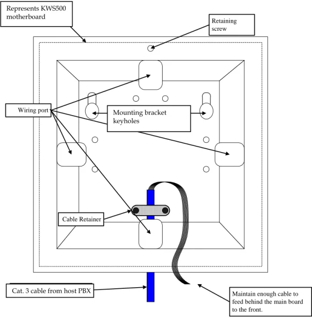
After the main board is removed, the rear chassis panel (fig.6) is exposed for mounting and wiring.
Mounting Brackets
Cat. 5 Cable from Host PBX Cable Retainer Wiring port Retaining screw Represents Dect 500 main board
Maintain enough cable to feed behind the main board to the front.
Fig. 6 Rear chassis panel (interior)
Remove one of the four wiring port punch-outs on the rear chassis panel and feed the analog station cable(s) through. Secure the analog station cable(s) to the rear chassis panel with the plastic retainer plate and T10 Torx screws included in the KWS500 package. Remove the
sheathing from four to six inches of the analog station cable, to allow room to maneuver the wires to align with the termination block on the front of the main board.
Install the main board onto the rear chassis panel and secure it with the T10 Torx screw, leaving all of the wires from the analog station cable accessible from the front of the system after the main board is installed (fig. 6).
3.4
Wiring the KWS500
The KWS500 requires one connection to an analog station port on the hosting PBX telephone system for each handset. Analog station ports are wired directly to the termination block mounted on the KWS500 Central Control Unit.
Represents KWS500 motherboard
Cat. 3 cable from host PBX
Mounting bracket keyholes
Use a set of wire strippers to expose approximately 3 mm of bare copper on each wire that will be connected to the KWS500. Be careful not to expose too much bare copper. Excessive bare copper can cause improper operation.
The master handset will register to port 0. From your wiring table, identify the wire color pair for the master handset. Insert that wire color pair into the two holes for port 0.
To connect a wire to the termination block, first insert a mini screwdriver into one of the top holes (fig. 7a). Start with port 0 on the left side of the termination block.
Press the screwdriver down so as to open the spring-loaded clamp in the bottom hole (fig. 7b). This works similarly to the wire connectors found on some stereo speakers.
Insert the exposed end of one wire into the open clamp in the bottom hole (fig. 7c).
a. Insert a mini screwdriver
into the top hole. b. Press down to open the clamp..
c. Insert the wire into the bottom hole.
Remove the screwdriver, allowing the clamp to close on the wire and lock the wire in place. Be careful to not clamp down on the wire insulation as this may lead to a poor connection. Pull gently on the wire to check for a firm connection before installing the next wire.
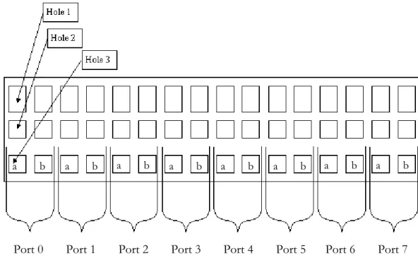
Add each a/b pair of wires to the ports on the termination block from left to right in sequence, per your wiring table (fig. 8).
The following chart describes the wire color pairs for Cat. 3 cabling and the associated ports on the termination block. If you use different cabling, the color pairs may vary.
Cable Cat. 3 Color Pair Port
Blue White / White Blue 0 Orange White / White
Orange 1 Green White / White Green 2 1
Brown White / White Brown 3 Blue White / White Blue 4 Orange White / White
Orange
5
Green White / White Green 6 2
Brown White / White Brown 7
Port 0
Port 1 Port 2 Port 3
Port 4 Port 5 Port 6 Port 7
a b
Fig. 8 Close-up of the KWS500 termination block
a b
a b
a b
a b
a b
a b
Fig. 9 KWS500 with Port 0 wired
Fig. 10 Main board wired and placed in chassis (only Port 0 is wired)
3.5
Mounting the KWS500
While the main board is removed, place the rear chassis panel against the mounting surface and use the keyhole cutouts in the mounting brackets to mark the locations for the mounting screws. Once marked, install the mounting screws as the construction requires. Included with the KWS500 package are two Phillips screws and two drywall anchors. Leave approximately 1/4” of each screw exposed for mounting the KWS500. Once you have wired the KWS500 and replaced the front cover, place the mounting brackets on the back of the KWS500 chassis over the screws and pull down on the unit to lock it into place.
3.6
KWS500 Base Station LED Conditions
LED Description
Flashing Green No master handset is subscribed. This mode is active for 15 minutes from the time power is applied to the KWS500 or until a master handset is subscribed.
Constant Green System is active. No active connections. Slow Flashing
Green The system is active with at least one current conversation. Fast Flashing
Red No master handset was subscribed within the 15 minute time period. Remove power for 10 seconds, then reconnect power to return to master handset subscription mode.
Slow Flashing
Red System is active with the maximum six simultaneous conversations. This indicates a busy condition.
If when the unit is powered up, the LED does not flash green and will not allow the subscription of a master handset, contact your KIRK vendor for assistance.4.
Master Handset Programming with KIRK
3040, 4020, and 4040 Handsets
The KWS500 provides handset programming capability through the use of a “master” KIRK 3040, 4020 or 4040 Handset to register or remove additional handsets. Any KIRK Handset can be registered as the master handset.
The KIRK 5020 Handset does not have programming capability. If a KIRK 5020 Handset is registered as the master handset, use the Administration Program for handset registration and removal.Prior to programming the KWS500, one handset must be charged and available for programming as the master handset.
All handsets that are to be registered and subscribed to the system should be present and charged.
Do not apply power to the KWS500 until programming of the master handset is about to begin. The master handset must be identified by subscribing a handset to the system within the first 15 minutes of the power-up of the KWS500. If the master handset is not subscribed in this time period, a rapidly flashing red LED on the front of the unit will indicate the expiration of the 15-minute subscription period. Unplug the KWS500 and plug it in again to restart this timer. For complete instructions on using the KIRK Handsets, please refer to the User Guide produced for each KIRK Handset model.
Master handset registration
When first applying power to the KWS500, it will automatically enter registration mode for 15 minutes. Registration mode is indicated by a fast-flashing green LED on the KWS500. During this time it is possible to subscribe a single handset to the KWS500.
This KIRK Handset becomes the master handset from this point forward. Only one master handset is allowed per system.
KIRK 4040 Handset
Opens menus
Scrolls left Scrolls
right
Confirms menu selections (long press turns handset off)
4.1
Master Handset Programming Step-by-Step
Configuration of the KIRK 3040, 4020, or 4040 master handset and subsequent handsets is a multi-step process. Each of these steps is expanded in detail in the sections below.
• Subscribe the master handset.
• Enter the master handset’s PBX extension number.
• Obtain the serial number of an additional handset.
• Add an additional handset via the master handset (register its serial number and assign it an extension number).
• Subscribe a handset.
• Remove a handset.
4.2
Subscribing the Master Handset
• Select the KIRK 3040, 4020, or 4040 Handset designated as the master handset.
• Power up the KWS500 and only the master handset (the LED in the center of the unit will flash green, indicating the unit is allowing subscription of the master handset).
• Press the
MENU
key.PROFILE SETUP
displays.• Press the
<
REDIAL
key twice to scroll to theLOGIN
menu.• Press the
3
MUTE
key.SELECT LOGIN
displays.• Press the
>
BOOK
key once.SUBSCRIPTION CREATE
displays.• Press the
3 MUTE
key.SUBSCRIPTION SEARCH ID
displays.• The handset is now searching for a signal from the KWS500. Once located, the Access Rights Identity (ARI) number of the KWS500 will display. This number can be found on the back panel of the KWS500.
• Note the ARI number: _____________________________1
• Press the
3
MUTE
key.CREATE SYSTEM 1 AC: ________
displays.• Leave the access code (AC) field blank, and press the
3
MUTE
key.SUBSCRIPTION WAIT
displays.• When the subscription is complete, a single confirmation tone will be heard and the radio icon will appear in the lower left corner of the display.
The master handset is now subscribed, and further programming may take place.
1 Access Rights Identity number, a 12-digit number that specifically identifies the DECT system. Each KWS500 produces a unique ARI number that identifies it from any other KWS500. The ARI number is located on the back panel of the unit.
4.3
Entering the Master Handset’s Extension Number.
• On the master handset, press the
MENU
key, and press the>
BOOK
key once to scroll to theEXT. SERVICE
menu.• Press the
3
MUTE
key.• Press the
>
BOOK
key three times to scroll to theRead/Write Userdata
menu.• Press the
3
MUTE
key.The serial number (
IPEI
1) of the master handset displays.• Press the
3
MUTE
key.• Enter the extension number for the master handset.
• Press the
3
MUTE
key.• Power cycle the handset: press and hold the
3
MUTE
key for two seconds to power it off, then press the key to power it on.The extension number will display.
4.4
Obtaining a Handset’s Serial Number
Each KIRK Handset has a unique serial number. It is a 12-digit number, easily located on the KIRK label on the outside of the handset packaging, or on the body of the handset on the floor of the battery compartment. This number can also be viewed on the KIRK 3040, 4020,or 4040 Handset’s display screen, where it is called the International Portable Equipment Identity (IPEI) number.
Example: 00077 1234567
To view the serial number on the handset packaging, look on the end of the package for a label with the Polycom logo and a small bar code. The serial number is directly above the bar code.
1 International Portable Equipment Identification number, synonymous with handset serial number.
To view the IPEI number on the handset’s display screen, do the following:
• Power on the handset.
• Dial
* * * *
, then press the<
REDIAL
key. TheIPEI
number displays.4.5
Adding Additional Handsets via the Master Handset
More KIRK Handsets can be added to the system with the KIRK 3040, 4020, or 4040 master handset. After subscribing the master handset and assigning it an extension number, use the master handset to perform the following steps to add (register) subsequent handsets to the system, including KIRK 5020 Handsets.
• Obtain the serial number and host PBX extension number for each additional handset.
• On the master handset, press the
MENU
key.• Press the
>
BOOK
key once to scroll to theEXT. SERVICE
menu.• Press the
3
MUTE
key to select the menu.• Press the
>
BOOK
key three times to scroll to theRead/Write Userdata
menu.• Press the
3
MUTE
key to select the menu.• The display will show the serial number (
IPEI
) of the master handset assigned toCHAN 0
. Press the>
BOOK
or<
REDIAL
key to scroll to the next available channel.• Once an available channel is located, enter the serial number of the handset to be registered on the channel.
• Press the
3
MUTE
key.• Enter the extension number assigned from the host PBX for the additional handset.
• Press the
3
MUTE
key. It is now possible to subscribe the additional handset.• To subscribe the additional handset, follow the procedure described in Subscribing a Handset. (If the handset is a KIRK 5020 handset, see Section 6 KIRK 5020
4.6
Subscribing a Handset
Do the following steps to subscribe a KIRK 3040, 4020, or 4040 Handset. The handset must be added to the system as described above before subscribing it. For instructions on how to register and subscribe a KIRK 5020 Handset, see Section 6 KIRK 5020 Handset Programming.
• On the handset to be subscribed, press the
MENU
key.• Press the
<
REDIAL
key two times to scroll to theLOGIN
menu.• Press the
3
MUTE
key to select the menu.SELECT LOGIN
displays.• Press the
>
BOOK
key one time.SUBSRIPTION CREATE
displays.• Press the
3
MUTE
key.If radio coverage from the KIRK Wireless Server is present, the ID number of the system (ARI number) will display.
• After the ID number appears, press the
3
MUTE
key one time to accept the subscription.• The handset will prompt you for an access code (AC). Leave the field blank.
• Press the
3
MUTE
key.SUBSCRIPTION WAIT
displays.The handset is now attempting to subscribe to the KWS500. This may take several minutes; do not be alarmed.
• If successful, the handset will beep and return to the idle condition. The startup text will be replaced by the PBX extension number assigned to the handset, and the radio icon will appear in the lower left corner of the display.
• If a subscription was not successful, the handset will show
SUBSCRIPTION
FAILED
in the display. The subscription period may have timed out, or another error may have occurred. Repeat steps 1 through 9. If still no subscription, contact your KIRK vendor for assistance.• Repeat the steps in the above two sections to register and subscribe the remaining handsets.
4.7
Removing a Handset
It is sometimes necessary to remove a handset from the system. You can use a KIRK 3040, 4020, or 4040 master handset to do this. If the master handset is a KIRK 5020 handset, use the
Administration Program to remove handsets.
It is necessary to remove a handset from the system when:
A serial number was incorrectly entered during the handset registration process (it cannot be edited by the master handset). In this case, the handset must be removed from the system and added again with its correct serial number.
A handset needs to be replaced for any reason. It must be removed from the system before adding the replacement handset.
• On the master handset, press the
MENU
key• Press the
>
BOOK
key once.EXT.SERVICE
displays.• Press the
3
MUTE
key to select the menu.• Press the
<
REDIAL
key twice.Delete Userdata
displays.• Press the
3
MUTE
key.• Press the
>
BOOK
key until the serial number of the handset you would like to remove displays (channels 1 through 7).• Press the
3
MUTE
key to remove the handset.• Press the
MENU
key to exit. Should the master handset become damaged or in need of replacement, a PC with the Administration Program installed must be connected to the system with a KIRK Programming Cable to delete the old master handset and register a new master handset. It is not possible to remove a master handset from the system without the Administration Program and programming cable. Contact your Polycom vendor for assistance.5.
Handset Special Features
This section describes how to program some popular special features into KIRK 4020, and 4040 Handsets. The complete array of handset features is covered in your KIRK Handset’s User Guide. (These features are also available on the KIRK 5020 Handset. See the KIRK 5020 Handset User Guide for instructions.)
5.1
Long Key Press (Speed Dial) for PBX Features (Only KIRK
4020/4040)
Your PBX system has features (such as Call Forwarding or Call Pickup) that are activated by key codes. See your PBX’s user guide for a list of these features and their codes. Your KIRK Handset can be programmed to activate a feature with a single long key press. Up to ten feature codes can be programmed into a handset. Each feature will activate with a long press of a designated key (0 – 9).
Implementing the long key press function for feature codes is a two-step process. First set the long key press “speed dial” function, then assign a key and enter the feature code you wish to place on “speed dial.”
Setting the long key press function
• Press the
MENU
key.PROFILE SETUP
displays.• Press the
3
MUTE
key.SET PROFILE
displays.• Press the
<
REDIAL
key once.SET PROFILE – ADVANCED
displays.• Press the
3
MUTE
key.• Press the
>
BOOK
key two times.ADVANCED – LONG KEY
displays.• Press the
3
MUTE
key.• Use the
<
REDIAL
or>
BOOK
key to scroll untilSPEED DIAL
displays.• Press the
3
MUTE
key.LONG KEY TIM
displays. (This function can be used to adjust the timing of a “long key press.” The default time is two seconds.)• Press the
MENU
key to exit.Assigning the “speed dial” long press key and entering the feature code
• Press the
MENU
key.PROFILE SETUP
displays.• Press the
<
REDIAL
key three times.MENU – SPEED DIAL
displays.• Press the
3
MUTE
key.A list of digits representing keys 0 – 9 displays.
• Use the
<
REDIAL
or>
BOOK
key to scroll until the number of the key you wish to program for the long key press reaches the top of the display.• Press the
3
MUTE
key.ENTER NO. (KEY #)
displays.• Enter the number string for the feature code.
• Press the
3
MUTE
key.Now when you long-press the designated key, the handset will activate the chosen feature.
5.2
Assigning a Name to a KIRK 4020/4040 Handset
It is possible to assign a 24-character alphanumeric name to the display of a KIRK 4020/4040 Handset as the startup text for that handset.
• Dial
* * * *
.• Press the
>
BOOK
key.• Press the
3
MUTE
key to begin entering the name.• Use the keypad to enter the new startup text (name).
• Press the
3
MUTE
key when complete. The handset will return to the idle condition.• Activate the new text by pressing the key.
PROFILE SETUP
displays.• Press the
3
MUTE
key to select the menu.• Press the
<
REDIAL
key once.SET PROFILE – ADVANCED
displays.• Press the
3
MUTE
key to select the menu.• Press the
<
REDIAL
key four times to scroll toADVANCED – STANDBY
TEXT
.• Press the
3
MUTE
key.STANDBY TEXT ON
displays.• Press the
<
REDIAL
key to toggle the standby text toOFF
.• Press the
3
MUTE
key to confirm the selection.• Press the
MENU
key to exit. When you assign a name to a handset, it appears only on that handset’s display. It will not display on another handset’s Caller ID display.6.
KIRK 5020 Handset Programming
To register a KIRK 5020 handset as the master handset, see Master handset registration on page 31. The master handset can then be subscribed by using its menu, or by using the Administration Program. Additional handsets must be registered using the Administration Program and
subscribed using the handset’s menu as described below.
If the master handset is a KIRK 5020 Handset, you must use the Administration Program for all programming of additional handsets.
A KIRK 3040, 4020 or 4040 Handset subscribed as the master handset can be used to register a KIRK 5020 handset as described in Section 4.5 Adding Additional Handsets via the Master Handset.KIRK 5020 Handset Softkey text Display center Status bar Navigation key Right softkey On/off power On/off hook
Subscribing a KIRK 5020 Handset
Follow the steps below to subscribe the KIRK 5020 master handset or any additional handset that has been registered to the system (use the Administration Program for additional handset registration).
• Press the
Menu
softkey.• Scroll to
Settings
and press theSelect
softkey.• Scroll to
Advanced
and press theSelect
softkey.• Scroll to
Login
and press theSelect
softkey.• Scroll to
Create Login
and press theSelect
softkey.• The KWS500 system number will display. If more than one system’s number displays, scroll to the desired number. Press the
Select
softkey.• The handset will prompt you for an access code (AC). Leave the field blank. Press the
OK
softkey.• The handset will now connect to the system and be operational.
If you have not yet done so, download and install the KIRK Administrative Program and use it for further handset programming.
6.1
KIRK Administration Program
The KIRK Administration Program is used to register and program KIRK Handsets, as well as to program your KWS500. The only Administration Program screen used for handset programming is the Registration screen.
The default IWU (Inter Working Unit, a term for the analog interface card that provides the connections between the PBX lines and the radio channels for the wireless handsets) settings for KWS500 cover the most common PBX settingsRequired tools for handset programming
A copy of the KIRK Administration Program software (v8.09 or higher) A laptop PC supporting Windows 98 or higher, with a 9-pin male serial port A KIRK Programming Cable for direct connection to the KWS500 (PN: 1403 3800)
6.2
Downloading the Administration Program
• If you do not have a copy of the KIRK Administration Program, it can be downloaded from www.kirktelecom.com.
• From the
Home
page, clickINSTALLER>Software
Downloads>Administration Program
.• Locate the current version of the KIRK Wireless Server Administration Program for Windows.
• Click the
Download
icon to begin the download of the file.• The download progress bar will display.
• The KIRK Administration Program
Setup Wizard
will begin. Click theNext
button.
• Click the
Browse
button if you would like to select a different destination folder. Click theNext
button to continue.• Click the
Browse
button if you would like to select a differentStart Menu
folder. Click theNext
button to continue.• Select the
Launch CCFP Adm
check box if you want the program to start.6.3
Connecting to the KIRK Wireless Server 500
Begin by installing the KIRK Administration Program on your PC, as described above.
• Connect one end of the KIRK Programming Cable to the KWS500 and other end to the 9-pin serial COM port on your laptop. Note which COM port you are using.
• Double-click the
KIRK Administration Program
icon to start the program.• As soon as the program starts to load, the
Welcome
screen appears. The Administration Program loads automatically and the main configuration screen appears.• (Conditional) At the bottom of the
Welcome
screen, theCurrent
Com
Settings
are listed. If necessary, click the
Change Communications Configuration
• Select the desired
COM
port (only from 1-10 is available) and connection type.
• If the KIRK Administration Program fails to connect with the KWS500, a warning message will appear indicating that there is problem.
• Confirm the cable being used.
• Confirm the
COM
port setting.• Confirm the
DIRECT
orMODEM
setting.The problem must be resolved before the KIRK Administration Program is able to run. Contact your KIRK vendor for assistance.
6.4
Handset Registration
Once your laptop PC connects to the KWS500, the Registration tab screen appears. This is the screen you will use to register and program your KIRK Handsets.
The Registration tab screen allows the installer to add, remove, or edit handset information such as the Serial Number, Name, Standby Text, and Presentation Text.
The KIRK handset must have its unique 12-digit serial number registered to the KWS500 database before subscribing the handset is possible.
Access codes
For an added level of security when registering a handset, it is possible, through the Registration tab screen, to assign an access code (AC No.) for use during subscription. This access code is not necessary, and may be skipped if desired. If an access code is entered, the access code must be used during the subscription process.
User Information Grid
The User Information Grid displays the eight radio channels available for handset subscription. A handset is assigned to a specific channel by selecting a channel and entering the handset’s serial number in the Serial No. field of the Current User Data section. The master handset automatically registers to channel 0 of IWU 0. (IWU: InterWorking Unit, a term for the analog interface card that provides the connections between the PBX lines and the radio channels for the wireless handsets.) Manual registration of the master handset is an option, as described below in Add a new handset.
Once the handset has been assigned to a channel and added to the KWS500 database, it may then be subscribed to the KWS500 using its menu.
6.5
How to Add, Edit, Move, or Delete a Handset
Add a new handset
• Connect your PC to the KWS500 with the KIRK Programming cable.
• Start the Administration Program. The program will open in the
Registration
screen.
• Highlight a line in the
User Information Grid
to select theChannel
you are assigning to the handset.• Under
Current User Data
, enter the handset information:•
Serial No.
– The 12-digit IPEI number identifying each unique handset (example:00077 0654321
).• Username– Name assigned to the handset.
• Local No. – PBX extension number. (This MUST match the PBX extension number assigned to the channel. See Section 2 Site Preparation and the Wiring Table in the
Appendix.)
• Standby Text– Appears on the user’s handset screen when the handset is in standby mode.
• Presentation Text– Appears on the calling handset’s screen when calling the user’s handset.
When entering the IPEI serial number, take care to enter the space after the fifth digit.All handset serial numbers consists of 13 digits. Enter only the first 12. To locate the handset serial number (SN):
• Look at the KIRK label on the handset’s box, or
• Remove the rear cover and lift the battery (SN is printed on a label under the battery), or