RF-CePal: A Universal Remote Control based on
MEMS accelerometer
Juhi Ranjan, Hiren Shah, Sanika Joshi, Brijesh Chokhra and Prabhat Ranjan
Dhirubhai Ambani Institute of Information and Communication Technology(DA-IICT), Gandhinagar (India) - 382007
{juhi.ranjan, shah.hiren86, sanika.joshi02, birju.chokhra}@gmail.com, [email protected]
Abstract— 'RF-CePal' is networked sensor device to assist people with restricted finger movements. Many electrical/electronic equipment can be operated using IR based remote control. As these remote controls take user input using push buttons, persons with restricted finger movement (e.g those with cerebral palsy) cannot operate such equipment. Taking advantage of MEMS accelerometer, we recognize gross movements of hand and map them to important functions of the equipment to be operated. We had earlier developed a device in which IR transmitter was integrated in the device along with sensor. However many users have problem pointing it towards the equipment to operate it reliably. In this paper, we report our work on developing a two part networked system communicating via zigbee based wireless link to overcome this difficulty. First part of the device(body device) containing sensor is placed on the body part (e.g hand/wrist) and the other part (base device) is pointing in direction of IR receiver of equipment. Tilt angle of hand is used as input to device (e.g left tilt changes the channel on TV). Based on preliminary trials, we have made design modifications to make the system more suitable and cheaper. This system is now being made available to users.
1. INTRODUCTION
“RF-CePal” is a set of networked sensor devices and meant to allow a person with restricted finger movements (e.g some with cerebral palsy) to operate an equipment from distance. Many equipment today come with remote control as standard facility. Some equipment have such facilities as option. For example, we can add remote control facility to light and fan. Remote controls take input from users in the form of buttons, which are pushed using fingers. Those without fine control of fingers find it difficult or impossible to operate remote control with push button.
According to the National Institute of neurological Disorders and Strokes, [1] cerebral palsy can be defined as "any one of a number of neurological disorders that appear in infancy or early childhood and permanently affect body movement and muscle coordination but don’t worsen over time". Many people affected with cerebral palsy have trouble with finger movement, and cannot control their peripheral equipments such as fan, light, A/C etc. They need someone to assist them for doing these things. The remote control of
“RF-mounted device communicates this information to the base station, which then sends infra-red control signals to the appropriate equipment.
Persons with Cerebral palsy[2] also have limited mobility of lower limbs many times. With limited mobility and not being able to operate remote control makes them dependent on caregivers for many simple tasks that we take for granted. This device opens up a way to provide self-reliance to persons with such issues and improve their quality of life.
2. PREVIOUS WORK
Assistive technology devices are tools, equipment, or services that are designed to compensate for, or enhance the function of some physical or mental ability that is impaired. A lot of work has been done in ‘Augmentative Communication Devices’. BIGmack[3] is a device with pre-recorded messages on device with touch-screen that helps the child communicate, what he wishes to say, by touching different parts of the screen. Then there is a device called Delta Talker[3], which resembles a computer keyboard, but instead of writing words and sentences, different pictures and words are put together to make a sentence.
There are hi-tech devices which include computer boards attached to electronic wheelchairs that allow a person with severe cerebral palsy related problems to both travel in the outside world and engage it with meaningful words and speech. Some other intuitive technology has made it possible for a camera to translate eye movements and blinks into computer input. The camera mounts just below the computer screen, and uses infrared light to track a person's eye movement and estimate with great accuracy what portion of the screen they are looking at. So a person would be able to simply look at the phrase they wanted to say on the computer screen and blink twice (for example) to select it.
Laser beam switches [4] (where the switch is activated by breaking the beam) or pressure sensitive floor switches can be installed in doorways to activate lights as somebody moves around their house. A person can move their wheelchair to a certain spot in the room and activate a floor switch which will turn on the television.
However these augmentative communication and other assistive devices come at a price. Also, even if the patient is able to communicate his thoughts, he would need the constant assistance of a helper to do whatever he wants to be done. Even simple things like increasing and decreasing the speed of fan are not possible for him because he cannot make accurate finger movements.
3. VARIANTS
We are making two different variants of this device:
1. Single part device being called CePal – This device is cheaper, but may have some limitation based on degree of hand control of the user since it depends on line-of-sight from user's hand to equipment receiver
2. Two part system connected through wireless link being called “RF-CePal” - This system consists of a hand mounted device and a base device. Hand mounted device has an accelerometer to sense hand tilt and a wireless communication link. When sensor detects appropriate tilt, it communicates to base device, what user action has happened. In this, equipment is always aligned with the IR transmitter and is always in line-of-sight. This device costs more as compared to the first one but is more flexible and reliable.
The rest of the paper now discusses this second variant, which is being called “RF-CePal”.
4. OPERATION
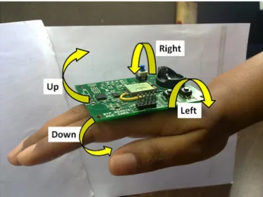
Both the variants use a 3-axis accelerometer to monitor body part movement. In its simplest form, we recognize four movements of the hand/wrist. One can use other parts of the body as well. We recognize up/down/left and right tilt of the hand and use these as inputs to operate the equipment in lieu of the buttons being pushed as shown in Figure 1.
Fig 1. The directions currently recognized by “RF-CePal” remote
This allows us to map four major functions of any IR controlled equipment to these movements. Examples are given in Table I:
Hand tilt DVD TV/Set
Top Box
Up Select Channel Up
Down Exit/Stop Channel Down
Left Move Up Volume up
Right Move Down Volume Down
TABLE 1 : EXAMPLES OF COMMANDS
5. METHODOLOGY
There are two devices as part of this system, a hand mounted tilt sensing device, referred to as the ‘Remote’ and a table-top/ceiling fitted device to generate the Infrared signals, referred to as the ‘Base-station’. As mentioned earlier, the remote aims at detecting hand gestures using a tri-axial accelerometer. Currently only two of the axes are being used.
If the tilt detected by the accelerometer exceeds the threshold set for positive/negative directions of the two axes, then this information is communicated to the basestation through wireless link. The basestation keeps on listening for messages sent by the remote. Upon receiving the message, depending upon the command to be sent, the basestation transmits the stored signal to the equipment being controlled through the IR LED.
The sequence of events that take place is shown in Figure 2.
Supported Equipment
At a given time the device can operate single equipment. However user can change the equipment of operation through a hand gesture (currently we use single or double tap for this). We are making provision to choose between four equipment (e.g TV, Light, Fan, A/C) out of the database of supported equipment. As mentioned above it is easy to add unsupported equipment by field staff as long as it operates using IR based remote control. No modification needs to be made to the equipment. Control code for all the four equipment is stored on the basestation at the time of installation. The control code is sent to the equipment using IR LED Transmitter.
In the early stage, we are providing data of most popular equipment and new equipment can be added as per need. We are making provisions for a field staff to make the device learn new types of equipment by the use of a universal remote receiver, which may not have been supported in the current database. However as of now, we are only supporting those equipment, which can be operated using IR (Infra Red) based control. This covers more than 90% of the equipment with remote control capability for indoor home use.
IR Format Used
Many of the remote control that we have collected in our database use NEC Protocol [5]. Some others use variations of this.
The NEC protocol uses pulse distance encoding of the bits. Each pulse is a 560µs long 38 kHz carrier burst (about 21 cycles). A logical "1" takes 2.25ms to transmit, while a logical "0" is only half of that, being 1.125ms.
Figure below shows a typical pulse train of the NEC protocol. With this protocol the LSB is transmitted first. A message is started by a 9ms leading burst, which was used to set the gain of earlier IR receivers and is referred to as AGC(Automatic Gain Control) burst also. This AGC burst is then followed by a 4.5ms space, which is then followed by the Address and Command. Address and Command are transmitted twice. The second time all bits are inverted and can be used for verification of the received message. The total transmission time is constant because every bit is repeated with its inverted length.
Fig. 3. Typical pulse train of the NEC protocol 6. HARDWARE
We first developed a proof-of-concept device based on Meshbean board from Meshnetics[6]. After this we made an integrated device on custom PCB (version 0.5). These used 3-axis MMA7260QT[7] accelerometer, which gave analog output. Since then, we have replaced it with a digital output
MEMS accelerometer MMA7660FC[8] , which is interfaced to Zigbit [9]using I2C bus.
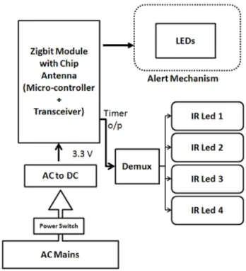
Fig. 4. Basestation version 1.0
As shown in Figure 4, the basestation version 1.0 is powered by AC mains, which is connected to a AC to USB adapter connected to FT232RL USB-UART chip on-board. This allows it to be used for data communication with a computer as well, if needed. The Zigbit here is connected to four IR LEDs through a demux. The goal is to be able to control four different equipment, using LEDs pointing towards their receivers from the same basestation. A flexi-neck pipe is provided to easily orient the LEDs to any
direction. A prototype of this is shown in figure 5 Also, indication LEDs have been added to show which equipment is currently being controlled.
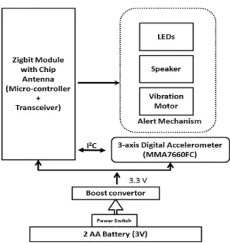
Fig. 6. Remote version 0.8
As shown in Figure 6, the remote in version 0.8 is powered by two AA type batteries connected to a Boost converter(MCP1640), which gives constant output of 3.3 V. Although in version 1.0, this is replaced with a single AA cell to miniaturize it. A 3-axis digital accelerometer is being used which is connected to the Zigbit via I2C bus. There are various
alert mechanisms available on the remote such as multiple LEDs, vibrator and speaker connected to the Zigbit which indicate sending of command. In figure 7, we show prototype version 0.8 of the hand mounted device.
7. SENSOR
As mentioned, currently we are using accelerometer to detect the hand tilt with respect to gravity but depending on need, one can use other sensors (e.g. gyrosensor) for other body parts (e.g head movements).
In “RF-CePal” version 0.5, we were connecting tri-axial analog accelerometer MMA7260QT to the internal ADC input pin of Zigbit. This accelerometer was constantly giving us analog values depending on the tilt of the device.
In “RF-CePal” version 0.8, we have replaced this with a digital accelerometer MMA7660FC.. This device is connected to the microcontroller via I2C. It has features such as tap
detection, double tap detection, ability to vary the sampling rate of the device. These additional features reduce the processing burden of the Zigbit and also provide various power conserving possibilities.
To provide support for multiple equipment at the same time, we are providing a way to switch the equipment being operated. This is being done by the use of double hand tap detection. We are making provision for maximum four equipment currently.
8. ALERT MECHANISM
During one of the test runs of this device, we realized that we needed to add some sort of an alert mechanism which indicates to the user that the tilt has been recognized and a command has been sent to the basestation. Since this device could be used by people with different disabilities, we wanted to provide an indication which would be easily comprehended by most people. In version 0.5, we had only visual indication in the form of LED. However some users have difficulty in seeing LED glow so as part of version 0.8 we have provided a sound and vibration alert facility as well. Device can be configured to select which one of these is active. In addition, since version 0.8 would be supporting the operation of 4 equipment, we have increased the number of indication LEDs to four, where each LED would indicate the equipment being controlled currently.
9. SOFTWAREIMPLEMENTATION
Software for this system is based on BitCloud embedded software stack [10] available from ATMEL. This stack implements ZigBee compliant networking stack and supports a number of hardware platform, in addition to Zigbit. This provides a rich set of API with full event based program development capability. We have used a Low Power application example as base software to modify and implement our application. We list some of the key additions and alterations to this to meet our needs:
For remote:
• Wrote the device driver for MMA7660FC accelerometer. Accelerometer is put in mode to detect tap, tilt and shake.
• Added the logic for tilt threshold detection, double tap detection
• Driver for four Indicator LED, Motor and Vibrator was written
For base station:
• Code added for generating IR control signal • Support for Demultiplexer added
10. OPTIMIZATIONS
Energy Optimization
From version 0.8 onwards, the basestation is connected to AC mains and thus power supply is not an issue. However, the remote is equipped with additional alert mechanisms such as LEDs, vibrator and speaker, the energy needs to be conserved at that end. Since the accelerometer being used is a digital one, we put the microcontroller to sleep and use accelerometer interrupt to wake up the microcontroller when user action is detected. We set the accelerometer in auto-sleep mode, and choose a low sampling frequency, which suits our need. as well as reduce power consumption. We have tested vibrator and speaker to consume minimum energy by reducing the pulse duration and the operational current.
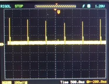
Communication between hand device and the base station is carried out only when some hand movements crossing threshold is detected. Device is programmed to go to sleep and wake up every one second. This can be seen in figure 8, where current consumption trace with time is shown. Pulses are of 40 ms duration with first peak corresponding to transmission mode.
Size Optimization
The size of the remote needs to be optimum, as the device would be fitted on top of the hand and thus we cannot make it either too small or too big. We have reduced the size/weight of the device by using only single AA cell as power supply. Surface mount components have been used to maximum on a double layer PCB to make the device fit in a 5 X 6 cm dimension.
Cost Optimization
Without serious cost optimization effort, we find the cost of “RF-CePal” device below $70 in small prototype volume. This cost be brought down at the production time by appropriate low cost component selection and volume pricing.
11. TRIALS
In the early stage of development, we carried out trials in lab by ourselves. After this we visited an organization called “Sparsh” - which is a pediatric neuro development therapy clinic situated in Navrangpura, Ahmedabad(India). This clinic works with Cerebral Palsy patients. We visited hospital for 3 days from 3rd to 5th January, 2010. We tested our device on 2 children Som and Devanshi under the guidance of Dr Mona Patel from the center. After 3 days we concluded that they can use the device with training. However, we received a lot of valuable feedback from Dr. Mona during these trials and the she was happy that this would be of great use to many of her patients.
The device that was tested here was a simple proof of concept breadboard device. We proceeded to make a integrated prototype based on custom PCB design.
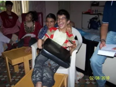
On Aug 2, 2010, we carried out next round of trials with the help of Ms Vimal Thawani, Mr Mihir Jani, Ms Jigna (all from Blind People's Association (BPA), Ahmedabad) and parents of children with CP. At one of the children's home, we carried trials with 3 children: Kajal, Parbati and Parth(as shown in Figure 9). To some extent they could use it and all of them seemed to be very happy in being able to control the equipment themselves. We allowed them to control a DVD player containing songs and pictures of flowers/animals etc. Figure 8: Current consumption in sleep/active mode
Figure 9: Parth operating DVD player using “RF-CePal” We also got valuable feedback during this trial and realized the change it can bring to these children's life. Leanring from this has been incorporated and mentioned in section 8. We could also see the the happiness on the face of the children with this new capability that device was providing to them. We recorded the video of the event for our own learning purpose and further improvements.
12. CONCLUSIONAND FUTURE WORK
We expect that CePal, “RF-CePal” and their variations would make a big difference in the life of thousands of persons with restricted finger movements in a very cost effective manner. During our interactions with the users during trials, we found that every person with CP is unique in his/her capabilities and we need to provide enough flexibility in the device to be able to customize it at field level. We expect that based on field trials and feedback from different users, we would continue to improve and innovate along to make this device more and more useful.
We plan to use MMA845xQ family, once it is released on commercial scale shortly. This would allow us to do more processing on the sensor itself and save on power. It would be possible to integrate different kind of sensors other than accelerometer with this device based user capability. Such sensors include gyrosensors, EMG sensor and even sensors being developed to monitor brain activity.
13. ACKNOWLEDGEMENT
A number of DA-IICT students have participated in the early phase of the development of this device starting from Pallavi, Ramya, Prashant, Mohit and Hitesh. We acknowledge the contribution made by the following research engineers to make this device more professional: Ishan Shah, Nancy Shah, Sainath Nambiar supported by Kiran and Firoza. We would also like to thank institute management for providing continuous support for such work. The progress of this work would not have been possible without encouragement and financial support of Mrs Poonam Natrajan (Chairperson, National Trust), Mr Atul Prasad (CEO, National Trust) and other members of National Trust. We would also like to acknowledge the great support and cooperation provided by Blind People Association, Ahmedabad and Sparsh Clinic, Ahmedabad during trials.
14. REFERENCES
[1] “NINDS Cerebral Palsy Information Page”,
http://www.ninds.nih.gov/disorders/cerebral_palsy/cerebral _palsy.htm
[2] “Definition of Cerebral Palsy”, http://medical-dictionary.thefreedictionary. com/cerebral+palsy
[3] Kahn, Alisa Beth, “Assistive Technology for Children who have Cerebral Palsy: Augmentation Communication Devices”, http://www.newhorizons.org/spneeds/inclusion/ teaching/kahn.htm
[4]”Cerebral Palsy and Technology : Mobility”, http://www.computers-technology-cerebralpalsy.com/cerebral-palsy-mobility.html
[5] “NEC Infrared Transmission Protocol",
http://wiki.altium.com/display/ADOH/NEC+Infrared+Tran smission+Protocol
[6] “MeshBean Development Board”, http://www.meshnetics.com/dev-tools/meshbean/
[7]”MMA7260 Data Sheet”, http://www.freescale.com/ files/sensors/doc/data_sheet/MMA7260QT.pdf
[8]”MMA7660 Datasheet”, http://www.freescale.com.cn/ files/sensors/doc/data_sheet/MMA7660FC.pdf?fpsp=1
[9]”Zigbit Modules”, http://atmel.com/products/zigbee/ zigbit_modules.asp?family_id=676
[10]”Bitcloud Stack”, http://www.atmel.com/dyn/ products/tools_card.asp?tool_id=4495