PROCLAMATION ... II
ATTENTIONS ... III
CHAPTER 1 PRODUCT INTRODUCTION ... 1
1.1.PRODUCT APPEARANCE ... 1
1.2.MODEL DESCRIPTION ... 3
1.3.PRODUCT SPECIFICATIONS ... 4
CHAPTER 2 COMMUNICATION PORTS ... 7
2.1.CONFIGURATIONS ... 7
2.1.1. Functions ... 7
2.1.2. Pin Definition ... 8
2.1.3. Communications Support ... 9
2.2.HMICOMMUNICATIONS SETUP ... 34
2.3.MANY TO ONE ... 35
CHAPTER 3 SYSTEM CONFIGURATIONS ... 38
3.1.SETTING DESCRIPTION ... 38 3.2.SYSTEM SETTINGS ... 39 3.4.COMMUNICATION SETUP ... 41 3.5.LANGUAGE ... 44 3.6.PASSWORD EDITING ... 45 3.7.INTERFACE TEST ... 46
3.8.DATA TRANSFER METHOD ... 48
3.9.SPECIAL FUNCTIONS ... 49
3.10.EXECUTION ... 51
3.11.SYSTEM INFORMATION ... 51
Thank you for purchasing Shihlin Electric’s Human Machine Interface (HMI). Please follow the order of the chapters to read the instructions and operate the device.
A. If users apply the HMI to a non-industrial controlled product, Shihlin Electric shall bear no responsibility on any damage whatsoever.
B. The software will be updated irregularly to add in new features. If users find the functions are somewhat different from the manual contents, please go to Shihlin Electric’s website to download the latest information.
C. Even if the information or the HMI implies intangible or intellectual property rights of Shihlin Electric or third parties, Shihlin Electric does not guarantee or grant any user and/or third parties the use of the HMI.
D. Although this manual has been proofread many times, imperfection is inevitable. We look forward to your opinions. If you have any questions or suggestions, please contact us and we’ll very
To properly and safely operate this device, please read this manual and relevant guide carefully to fully understand the features of the device and correct way of using it.
A. Touch panel switch should not be used under ON / OFF wire abnormalities that may result in personnel injury or equipment damage, even lead to serious incidents.
B. Output signal may lead to serious incidents, thus must be equipped with monitoring circuits, such as limiters; and the system must be designed to have reset mechanism, so that conduction can be controlled by means other than the HMI, to prevent incidents resulting from malfunctions or failure of the touch panel switch.
C. The control switch of the HMI should not be used as an emergency stop switch for a device. To the health and safety conerns, the labor requires all industrial machinery system must be equipped with a mechanical, manually operated emergency stop switch; and for other types of systems, similar mechanical switches must also be provided to ensure safe operations.
D. Please do not shut down you computer, close the editor software or switch off the HMI, when a program is being edited or a HMI project is being transmitted. Doing so may crash the project program.
E. Do not use a document editing software or any other types of editing software to modify the project structure of this product. Doing so may crash the project program and result in disabled execution.
provided, allowing you to quickly learn the functions of the editing screens after reading the manual.
Chapter 1 Product Introduction
1.1. Product Appearance
The following Figure 1-1-1 shows the control panel of Shihlin Electric’s HMI EC207.
(a) (b)
(c)
Fig.1-1-1 Product Appearance (a) 3D Diagram (b) Side View (c) Front View
The following Figure 1-1-2 shows the schematic diagram of the hardware structure of Shihlin Electric EC207, including USB port,
Power Lamp
Action Lamp
Ethernet port, COM port as well as USB Host, audio output port, memory slot and a 24V power connector.
Fig. 1-1-2 Product Appearance
SD Card Interface COM Port Interface DC24V USB/Ethernet USB Host/ Sound Interface
1.2. Model Description
The models and corresponding features of Shihlin Electric’s HMI are listed in the following Table 1-2-1.
Table 1-2-1 Mode Codes (a) Model Description (b) Corresponding Types
Name Description
(1)Model Name EC2:EC200 Series
(2)Panel Size 07:7 inches 10:10.2 inches (3)Monitor Type C:Color
T:TFT LCD (4)Model Type 00:Basic Type
11:Multi-functional Network (a) Model Support 00 Basic Model 11 Multi-functional Network COM1 ○ ○ COM2 ○ ○ COM3 ○ ○ USB ○ ○ Ethernet ╳ ○ Memory Card ○ ○ (b)
1.3. Product Specifications
Table 1-3-1 Hardware Specifications
Model
Parameter EC207-CT-00 EC207-CT-11 EC210-CT-00 EC210-CT-11
Processor 32Bit RISC 400MHz
D is p la y S p ec if ic a tio n s
Color Display over 65,000 colors
Monitor TFT LCD
Screen Size(inches) 7 10.2
Resolution(DPI) 800×480 800×480
Brightness(cd/m2) 300 350
Contrast 500:1 300:1
Viewing Angel Range 50/70/70/70 (T/B/R/L) 45/65/65/65 (T/B/R/L)
Backlight LED
Backlight Life Under room temperature of 25℃, the half-life is greater than 30,000 hours. T o uc h P a ne l Spe ci fic a tio ns
Touch Panel 4-wire resistive
Touch Resolution Over 2mm
Life Over a million times
Hardness of Surface 4H
Battery Life Two years from manufacturing date
C o mmun ic a S eri a l P o rt s COM1 RS-232/422/485 COM2 RS-232/422/485 COM3 RS-232
Table 1-3-1 Hardware Specifications (continued)
This is a Class-A information product, which can cause radio frequency interference when used in a living environment. Under such a circumstance, take appropriate measures.
Model
Parameters EC207-CT-00 EC207-CT-11 EC210-CT-00 EC210-CT-11
E nv ir o n me nt Spe ci fic a tio ns Operating Ambient
Temp. 0~45℃(avoid freezing)
Storage Ambient
Temp. -20~60℃(avoid freezing)
Operating Ambient
Humidity 10%~85%RH(non-condensing environment) Environmental
Tolerance
Non-corrosive, non-conductive environment
Vibration Resistance
IEC61131-2 Compliant,
Vibration Frequency:10~150Hz,Acceleration:9.8m/s2(1.0G),X,Y,Z directions, each 12 times
Noise Resistance In compliance with IEC 61000-6-2:2001
Rated Voltage DC 24V±15% Ins ta lla tio n C o ndi tio ns
Water Resistance Front Cover IP65(dust and drip-proof design)
Cooling Method Natural Air Cooling
Exterior Dimensions W×H×D(mm)
200x146x42.5 271x213x50
Hole-cutting Size (mm) 192x138 259 x 201
Weight (kg) 0.85 1.4
1.4. Wiring Description
Use the included power supply terminal. Loosen the screws of the power supply terminal, and then plug the power cord into the power supply terminal in accordance with the instructions shown on the power input on the back of the HMI. Use a straight screwdriver to tighten the screws of the power terminal, and finally plug the power supply terminal into the power input of the HMI. This is shown in Figure 1-5-1.
(a) (b)
Fig. 1-5-1 Power Supply Wiring (a) Rear View (b) Power Supply Terminal
Before plugging or un-plugging the power supply terminal, be sure to cut off the power source first to avoid possible
Chapter 2 Communication Ports
2.1. Configurations
2.1.1. Functions
Shihlin Electric’s HMI series provides multiple communication ports, whose mechanisms are described in the following Table 2-1-1.
Table 2-1-1 Functions of Communication Ports
Mechanism Description
Data Transmission
Able to transmit screen data via Ethernet and USB, and provide By Pass functions to transmit programs to PLC via the HMI’s COM port.
Multiple Communication
Ports
COM1/COM2/COM3、USB and Ethernet
Multi-brands Support
Support multiple brands of PLC models, Shihlin inverter, thermostat, and provide MODBUZS communication.
When the MODBUS communication is selected, it can connect up to 31 units, and the station numbers are set to 1~31.
2.1.2. Pin Definition
COM port diagram is shown in the following Figure 4-1-2. COM1/COM2 ports are 9-Pin female connectors, and COM3 port is a 9-Pin male connector. The pin definitions are listed in the following Table in 2-1-3.
Female Connector Male Connector
Fig. 2-1-2 Communication Port Diagram Table 2-1-3 Pin Definitions
PIN
COM1 COM2 COM3
RS-23 2 RS-422 RS-485 RS-232 RS-422 RS-485 RS-232 1 - TX+ A - TX+ A - 2 TX - - TX - - TX 3 RX RX RX 4 - RX+ - RX+ - 5 GND GND GND 6 - RX- - - RX- - - 7 RTS - - - RTS 8 CTS - CTS 9 - TX- B - TX- B - 1 9 5 6 5 6 1 9 1 9 5 6
2.1.3. Communications Support
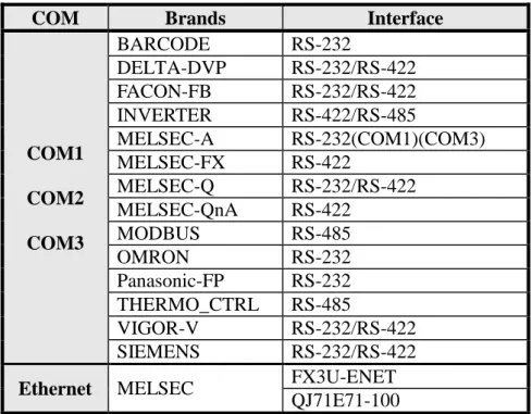
The following Table 2-1-4 lists the brands of products supported by the ports.
Table 2-1-4 List of Supported Devices
COM Brands Interface
COM1 COM2 COM3 BARCODE RS-232 DELTA-DVP RS-232/RS-422 FACON-FB RS-232/RS-422 INVERTER RS-422/RS-485 MELSEC-A RS-232(COM1)(COM3) MELSEC-FX RS-422 MELSEC-Q RS-232/RS-422 MELSEC-QnA RS-422 MODBUS RS-485 OMRON RS-232 Panasonic-FP RS-232 THERMO_CTRL RS-485 VIGOR-V RS-232/RS-422 SIEMENS RS-232/RS-422
Ethernet MELSEC FX3U-ENET
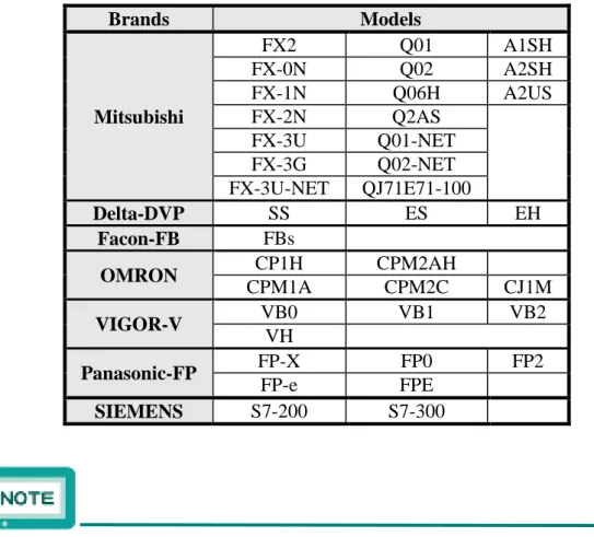
The following Table 2-1-5 lists the brands of PLC models supported by the HMI.
Table 2-1-5 Lists of Supported Models
Brands Models Mitsubishi FX2 Q01 A1SH FX-0N Q02 A2SH FX-1N Q06H A2US FX-2N Q2AS FX-3U Q01-NET FX-3G Q02-NET FX-3U-NET QJ71E71-100 Delta-DVP SS ES EH Facon-FB FBs OMRON CP1H CPM2AH CPM1A CPM2C CJ1M VIGOR-V VB0 VB1 VB2 VH Panasonic-FP FP-X FP0 FP2 FP-e FPE SIEMENS S7-200 S7-300
The HMI provides simultaneous uses of the 4 communication ports.
2.1.4. PLC Connections
a. Shihlin Inverter (SE/SH/SL/SS)
Configuration of the RS-422/RS-485 connection is shown in the following Figure 2-1-6. 1 (TX+) 4 (RX+) 5 (GND) 6 (RX-) 9 (TX-) RDA SDA SG SDB RDB HMI RS-422 INV (a) 1 (A) 5 (GND) 9 (B) RDA SDA SG SDB RDB HMI RS-485 INV (b)
Fig. 2-1-6 Invert Connection (a) RS-422 (b) RS-485
When the INVERTER connection is selected, it can connect up to 16 units, and the station numbers are set to 1~16. For connection to the SH inverter, SG terminal needs shielded grounding.
The devices IIW and IDW of inverter are write only, IIR and IDR are read only. The invalid actions such as reading value from the write only device or writing value to read only device will not be taken on HMI.
b. Shihlin Temperature Controller
Configuration of the RS-485 connection is shown in the following Figure 2-1-7. 1 (A) 5 (GND) 9 (B) DX+ DX-HMI RS-485 Temp. Controller
Fig. 2-1-7 Temperature Connection
When the THERMO_CTRL connection is selected, it can connect up to 31 units, and the station numbers are set to 1~31.
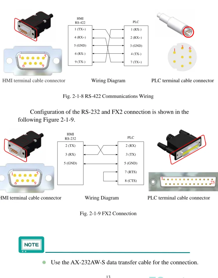
c. Mitsubishi FX Series
Configuration of the RS-422 connection is shown in the following Figure 2-1-8. 1 (TX+) 4 (RX+) 5 (GND) 6 (RX-) 9 (TX-) PLC 1 (RX-) 2 (RX+) 3 (GND) 4 (TX-) 7 (TX+) HMI RS-422
HMI terminal cable connector Wiring Diagram PLC terminal cable connector Fig. 2-1-8 RS-422 Communications Wiring
Configuration of the RS-232 and FX2 connection is shown in the following Figure 2-1-9. 2 (TX) 3 (RX) 5 (GND) 2 (RX) 3 (TX) 5 (GND) 7 (RTS) 8 (CTS) HMI RS-232 PLC
HMI terminal cable connector Wiring Diagram PLC terminal cable connector Fig. 2-1-9 FX2 Connection
Use the AX-232AW-S data transfer cable for the connection.
5 6 1 9 1 3 6 5 6 1 9 25 1
d. Mitsubishi FX Series – Computer Link
When the Mitsubishi FX Series is connected with an external
232-BD module, wire the RS-232 connection as shown in Figure 2-1-10.
HMI terminal cable connector Wiring Diagram PLC terminal cable connector Fig. 2-1-10 RS-232 Communications Wiring
The following table 2-1-11 lists the FX series external 232-BD module serial setting example, the actual set still mainly user needs.
Table 2-1-11 Lists of 232-BD module serial setting
BD module serial setting
Baud
Rate(Bps) Parity
Data
Length Stop Bit
CR/LF Select
PLC D8120 Device 232-BD(Type1)
9600 Even 7 1 None E886(HEX)
232-BD(Type4) CR&LF 6886(HEX)
5 6 1 9 5 6 1 9
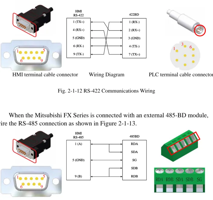
When the Mitsubishi FX Series is connected with an external 422-BD module, wire the RS-422 connection as shown in Figure 2-1-12.
1 1 ((TXTX+)+) 4 4 ((RXRX+)+) 5 5 ((GNDGND)) 6 6 ((RXRX--)) 9 9 ((TXTX--)) 422 422BDBD 1 1 ((RXRX--)) 2 2 ((RXRX+)+) 3 3 ((GNDGND)) 4 4 ((TXTX--)) 7 7 ((TXTX+)+) HMI HMI RS RS--422422
HMI terminal cable connector Wiring Diagram PLC terminal cable connector Fig. 2-1-12 RS-422 Communications Wiring
When the Mitsubishi FX Series is connected with an external 485-BD module, wire the RS-485 connection as shown in Figure 2-1-13.
1 1 ((AA)) 5 5 ((GNDGND)) 9 9 ((BB)) RDA RDA SDA SDA SG SG SDB SDB RDB RDB HMI HMI RS RS--485485 485485BDBD
HMI terminal cable connector Wiring Diagram PLC terminal cable connector Fig. 2-1-13 RS-485 Communications Wiring
5 6 1 9 1 3 6 5 6 1 9
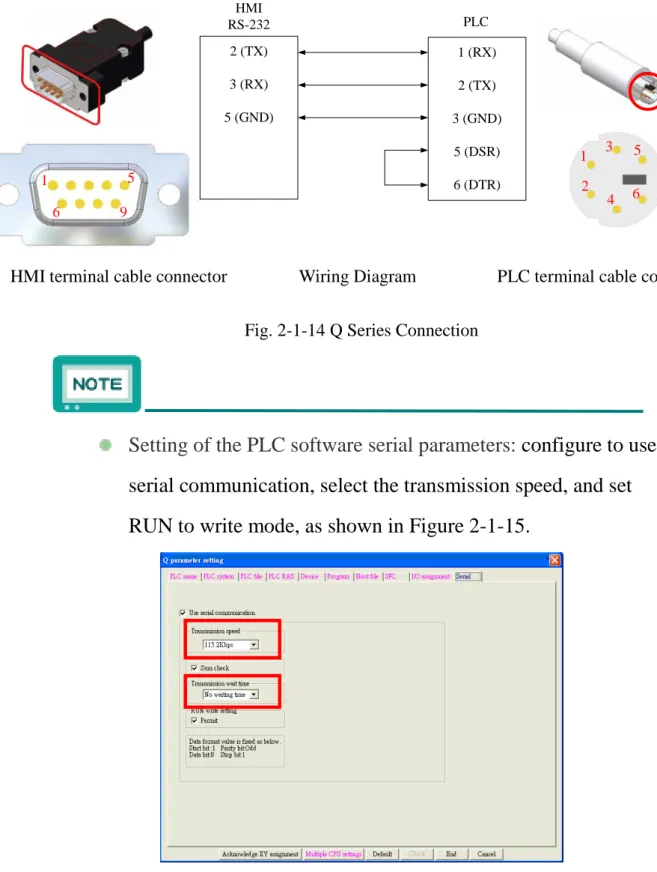
e. Mitsubishi Q Series
Configuration for the RS-232 connection is shown in the following Figure 2-1-14. 6 2 (TX) 3 (RX) 5 (GND) PLC 1 (RX) 2 (TX) 3 (GND) 5 (DSR) 6 (DTR) HMI RS-232
HMI terminal cable connector Wiring Diagram PLC terminal cable connector Fig. 2-1-14 Q Series Connection
Setting of the PLC software serial parameters: configure to use serial communication, select the transmission speed, and set RUN to write mode, as shown in Figure 2-1-15.
5 6 1 9 1 3 5 2 4 6
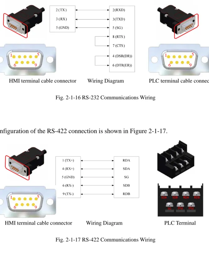
f. Mitsubishi Q Series – Computer Link
When the Mitsubishi Q Series is connected with an external QJ71C24 expansion module, wire the RS-232 connection as shown in Figure 2-1-16.
HMI terminal cable connector Wiring Diagram PLC terminal cable connector Fig. 2-1-16 RS-232 Communications Wiring
Configuration of the RS-422 connection is shown in Figure 2-1-17.
HMI terminal cable connector Wiring Diagram PLC Terminal Fig. 2-1-17 RS-422 Communications Wiring
5 6 1 9 5 6 1 9 5 6 1 9
To configure the communication settings for the Mitsubishi Q serie to be connected with an external QJ71C24 expansion module, execute the GX Developer software, and follow the steps shown below.
Step 1:Select the PLC parameters, and set the expansion model in the configuration column, then click the “Select” button to start the communication setting.
Step 2:After the model is selected, set up the communication configuration.
g. Mitsubishi QnA Series
Configuration for the RS-232 connection is shown in Figure 2-1-18.
2 (TX) 3 (RX) 5 (GND) PLC 2 (TX) 3 (RX) 5 (GND) 7 (DTR) 8 (DSR) HMI RS-232
HMI terminal cable connector Wiring Diagram PLC terminal cable connector Fig. 2-1-18 QnA Series Connection
Use AX-232AW-S data transmission cable to connect.
5 6 1 9 25 1
h. Mitsubishi A Series
Configuration for the RS-232 connection is shown in Figure 2-1-19.
2 (TX) 3 (RX) 5 (GND) 7 (RTS) 8 (CTS) PLC 2 (TX) 3 (RX) 5 (GND) 7 (DTR) 8 (DSR) HMI RS-232
HMI terminal cable connector Wiring Diagram PLC terminal cable connector Fig. 2-1-19 A Series Connection
Use AX-232AW-S data transmission cable for the connection.
5 6 1 9 25 1
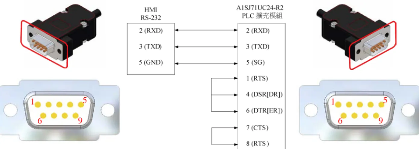
i. Mitsubishi A Series – Computer Link
When the Mitsubishi A Series is connected with an A1SJ71UC24-R2 expansion module, wire the RS-232 connection as shown in Figure
2-1-20.
HMI terminal cable connector Wiring Diagram PLC terminal cable connector Fig. 2-1-20 Connection with A1SJ71UC24-R2 expansion module
5 6 1 9 5 6 1 9
j. Delta DVP Series
Configuration for the RS-232 connection is shown in Figure 2-1-21.
2 (TX) 3 (RX) 5 (GND) PLC 4 (RX) 5 (TX) 8 (GND) HMI RS-232
HMI terminal cable connector Wiring Diagram PLC terminal cable connector Fig. 2-1-21 Delta DVP Connection
The PLC station internal number is 1 by default, so the component of the edit screen should have the station number set to 1 before the
communication can begin. This is shown in Figure 2-1-22.
1 3 6 5 6 1 9
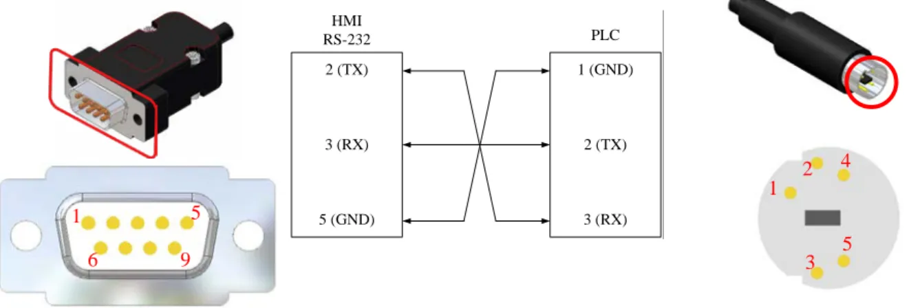
k. Fatek FB Series
Configuration for the RS-232 connection is shown in Figure 2-1-23.
2 (TX) 3 (RX) 5 (GND) PLC 1 (GND) 2 (RX) 4 (TX) HMI RS-232
HMI terminal cable connector Wiring Diagram PLC terminal cable connector Fig. 2-1-23 Fatek FB Connection
The PLC station internal number is 1 by default, so the component of the edit screen should have the station number set to 1 before the communication can begin. This is shown in Figure 2-1-24.
Fig. 2-1-24 Station Number Setup
Use FBs-232P0-9M data transmission cable for the connection.
2 4 1 3 5 6 1 9
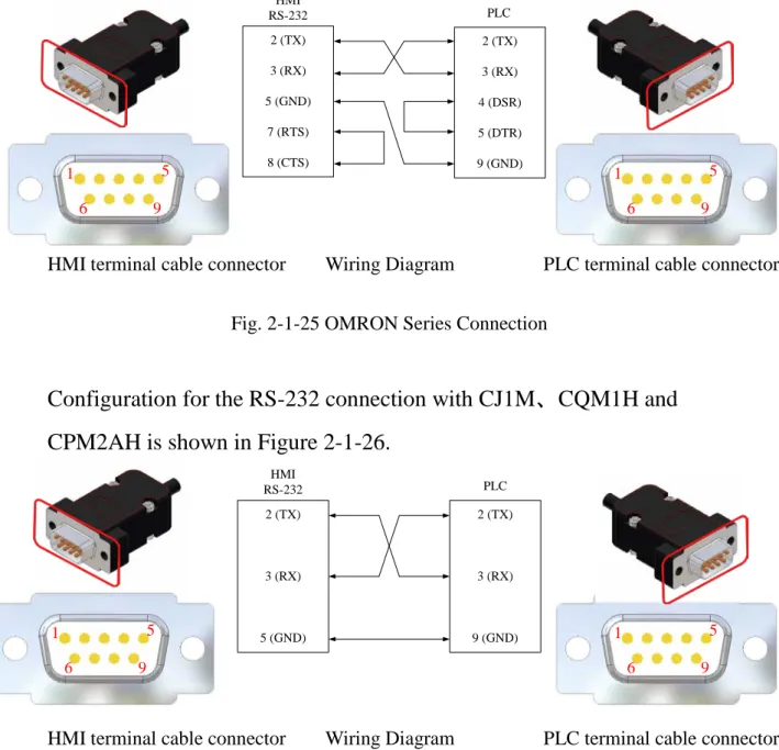
l. OMRON Series
Configuration for the RS-232 connection with CP1H and CP1L is shown in Figure 2-1-25. 2 (TX) 3 (RX) 5 (GND) 7 (RTS) 8 (CTS) PLC 2 (TX) 3 (RX) 4 (DSR) 5 (DTR) 9 (GND) HMI RS-232
HMI terminal cable connector Wiring Diagram PLC terminal cable connector Fig. 2-1-25 OMRON Series Connection
Configuration for the RS-232 connection with CJ1M、CQM1H and CPM2AH is shown in Figure 2-1-26.
2 (TX) 3 (RX) 5 (GND) 2 (TX) 3 (RX) 9 (GND) HMI RS-232 PLC 5 6 1 9 5 6 1 9 5 6 1 9 5 6 1 9
The CPM1A and CPM2C models have no RS-232 connectors, so they need adaptor cables. The applicable adaptor cables are shown in the following Table 2-1-27. The communications wiring is shown in Figure 2-1-28.
Table 2-1-27
PLC Model Adaptor Cable Model
CPM1A CQM1-CIF02
CPM2C CS1W-CN226T
HMI terminal cable connector Wiring Diagram PLC terminal cable connector Fig. 2-1-28 OMRON Series Connection
5 6 1 9 5 6 1 9
m. Panasonic Series
Configuration for the RS-232 connection is shown in Figure 2-1-29.
2 (TX) 3 (RX) 5 (GND) 1 (GND) 2 (TX) 3 (RX) HMI RS-232 PLC
HMI terminal cable connector Wiring Diagram PLC terminal cable connector Fig. 2-1-29 Panasonic Series Connection
4 1 5 2 3 5 6 1 9
n. Vigor V Series
Configuration for the RS-232 connection is shown in Figure 2-1-30.
4 2 (TX) 3 (RX) 5 (GND) 2 (RX) 3 (TX) 4 (GND) HMI RS-232 PLC
HMI terminal cable connector Wiring Diagram PLC terminal cable connector Fig. 2-1-30 Vigor V Series Connection
5 6 1 9 4 1
o. SIEMENS Series
Configuration for the RS-485 connection with S7-200 series is shown in Figure 2-1-31.
HMI terminal cable connector Wiring Diagram PLC terminal cable connector Fig. 2-1-31 RS-485 Communications Wiring
The S7-300 series needs a PC adapter to connect HMI. Configuration for the RS-232 communications wiring is shown in Figure 2-1-32.
5 6 1 9 5 6 1 9 5 1 1 5
p. ModBus
Configuration for the RS-485 connection is shown in Figure 2-1-33.
1 1 ((AA)) 5 5 ((GNDGND)) 9 9 ((BB)) DX DX++ DX DX--HMI HMI RS RS--485485 ControllerController
HMI terminal cable connector Wiring Diagram PLC terminal cable connector Fig. 2-1-33 RS-485 Communications Wiring
When the the RS-485 connection contains the groundis shown in Figure 2-1-34. 1 1 ((AA)) 5 5 ((GNDGND)) 9 9 ((BB)) DX DX++ GND GND DX DX--HMI HMI RS RS--485485 ControllerController
HMI terminal cable connector Wiring Diagram PLC terminal cable connector Fig. 2-1-34 RS-485 Communications Wiring
5 6 1 9 5 6 1 9 5 6 1 9 5 6 1 9
System default read mode is Mode1 and write mode is Auto in ModBus communication device setting. The HMI will use the fitted command when reading or writing. The users can customize the setting for special needs. The setting items are shown in Figure 2-1-35 below.
ModBus communication device setup Read Mode1 Support the group read.
Mode2 Not support the group read.
Write
Auto Support 0x06 and 0x10 command
0x06 Only support 0x06 command 0x10 Only support 0x10 command
q. Ethernet
To set up the communication protocol, click the manual, and
select to change HMI/Device/Model, and then selectFX3U-ENET or QJ71E71-100, and set the IP address to
192.168.1.XXX, as shown in Figure 2-1-36.
To configure the network settings of the Mitsubishi PLC, execute the GX Developer software, select your desired model device, and do the configuration on the left side of the window, as shown in Figure 2-1-37.
Fig. 2-1-37 Network Parameters Setup
The network configuration requires the setup of network type, starting I/O number, network number, group number and station number. Detailed parameters setting is shown in Figure 2-1-38.
Finally, it is the operational setting and open setting. Detailed parameter settings are shown in Figure 2-1-39.
(a) (b)
(c)
Fig. 2-1-39 Other Parameters (a) Module Settings (b) Operational Settings (c) Open Settings
The HMI default network address is 192.168.1.45. Users can define their own address; the Ethernet host IP address is also user-definable, if only it is different from HMI’s default IP address.
For network related settings, please refer to the manuals of the devices.
2.2. HMI Communications Setup
To make connection to various brands of PLC, please refer to the following Table 2-2-1 for the settings and set up the connection in HMI.
Table 2-2-1 HMI Communications Setup
Items Brands Baud Rates (bps) Data Length (Bits) Parity Stop Bit (Bit) PLC Station Number Mitsubish FX Series 9600 7 Even 1 N/A Delta DVP Series 1 (Initial Settings) Fatek FB Series OMRON 2 N/A Mitsubishi A Series 8 Odd 1 Q Series 19200 38400 57600 115200 QnA Series 9600 19200 38400 Panasonic FP0 9600 FP-e FPE FP-X 19200 FP2 115200 Vigor V Series 19200 7 Even SIEMENS S7-200 9600 8 S7-300 38400 Odd
2.3. Many to One
Multiple HMIs, up to 8 units, can be used to simultaneously monitor a single unit of the FA equipment. For the connection, network cable of cross-over twisted pair is required, as shown in Figure 2-3-1.
(a)
(b)
To set 8-to-1 monitoring, return to the system screen and click the
icon. Set the station number of the first HMI to 1, the system will then automatically establish the first HMI as sever, and orderly set the station numbers of the rest HMIs to 2~8 as clients. When the setup is done, click the save button.
Confirm the setup and send the file to the first HMI, which will then relay the file to the rest HMIs numbered 1~8, as shown in the following Figure 2-3-2.
After the server and clients are established, get the HMIs
numbered 1~8 back to the system screen, then click the
icon. Click the button as indicated in a red frame below,
the button will then switch to to indicate the connection is succefully established. This is shown in the following Figure 2-3-3.
Chapter 3 System Configurations
3.1. Setting Description
Please plug the power connector into a 24V power source to start the Shihlin HMI. The following Figure 3-1-1 shows the system screen after boot.
Fig. 3-1-1 System Screen
3.2. System Setup
Click the system setup icon, the following items will be available, as shown in Figure 3-2-1.
Fig. 3-2-1 System Setup
Description Remark
Touch Sound Open/close touch sound
N/A
Date & Time Adjust date & time
Brightness Brightness setting
After the setup is done, be sure to click the icon to save the settings in the system.
3.3. Power Setup
Click the power setup icon, the following items will be available, as
shown in Figure 3-3-1.
Table 3-3-1 Power Setup Items
Description Remark
Standby Mode
Go to Sleep mode after the standby time has elapsed
(min)
0~999
It needs to match up with the password set in the project.
3.4. Communication Setup
Click the Communication Setup icon, the following items will be available, as shown in Table 3-4-1.
Table 3-4-1 Communication Setup Items (continued)
Description Remark
Ethernet Setup Change the IP address and the
gateway.
IP address:192.168.1.45 gateway:255.255.255.0
Serial Setup
Change the parameters of the COM1/COM2/COM3 serial ports.
N/A
HMI St. No. Set the HMI station number. 0~8
Memory Load
Switch to memory/SD card/USB and download the data.
:Only read the project from the external memory.
:Read and download the project from the external memory.
Steps of NO Copy & Auto Copy: choose the external memory→click the No copy /Auto copy button→click the icon→click the delete button (the button under the directory of download & upload).
Dev. Station Set Control the device switch of
specific station number :Set up the device station number. mount:Read from USB or SD card
library/CSV data.
After the setup is done, be sure to click the icon to save the settings in the system.
The network settings are user-definable.
To delete external memory, be sure to first click the icon to remove the device. Doing so can ensure subsequent data
transfers between external memory and HMI.
Before using Ethernet to transfer data, set up the TCP/IP address first, as shown in the following Figure 3-4-2.
3.5. Language
Click the icon, users can change the display language. The system provides four languages including Traditional Chinese, Simplified Chinese, English and Japanese, allowing users to switch, as shown in Figure 3-5-1.
3.6. Password Edit
Click the Password Editing icon, the following items will be available, as shown in Table 3-6-1.
Table 3-6-1 Password Editing Items
Description Remark
Security Level Set up the password level 0~15
Old Password Set up the old password For the first setup, no old password is required. Enter up to 8 digits for the password.
New Password Set up the new password
Check Password Reconfirm the password
After the setup is done, be sure to click the button to save the settings in the system.
When the password is set to the highest level of 15, on the upper left corner of the execution screen, touch 5 times consecutively to get back to the system screen (if the time interval between two touches is more than five seconds, HMI will void the count), and then enter the highest-level password.
3.7. Interface Test
Click the Interface Test icon, the following test items will be available, as shown in Table 3-7-1.
Table 3-7-1 Interface Test
Description Remark
Display Pattern Test screen color
N/A
Touch Panel Test screen touch
points
Connect Port Test serial ports Please short-circuit the cable.
To test the serial port communication, please short-circuit the pin connection first, as shown in Figure 3-7-2.
2 (TX) 3 (RX) RS232 RS422 1 (TX+) 4 (RX+) 6 (RX-) 9 (TX-) (a) (b)
Fig. 3-7-2、Short-circuit Wiring Diagram (a) RS232 (b) RS422
When the setup is done, be sure to click the button to save the settings in the system.
3.8. Data Transfer
Use the By-Pass data transfer method, as shown in Figure 3-8-1.
Fig. 3-8-1、By-Pass Transfer Topology
3.9. Special Function
Click the Special Functions icon, the following items will be available, as shown in Table 3-9-1.
Table 3-9-1 Special Functions
Description Remark
List Editor
Use instructions to modify PLC and monitor the trapezoidal charts
1. Please connect to the PLC device.
2. The instruction list editor supports PLC of
Mitsubishi FX series and Shihlin AX series.
Start/Stop Server Start/close the network
monitoring
After the network is connected, click the “start server” button, and execute the simulation software to start the monitoring. Setup of IP address is required for the monitoring end.
To use instruction list editing and trapezoidal chart monitoring, please connect the PLC device via COM port. The connection is shown in Figure 3-9-2.
3.10. Run
To return to the execution screen, please click the icon to once again get back to the editing screen you were working on.
If there is no any screen data sent to HMI, you won’t be able to
use .
3.11. System Information
Click the icon on the upper right corner of the system screen to view the system information, as shown in Figure 3-11-1.
3.12. Resume
Click the icon on the upper right corner of the system screen to view the resume, as shown in Figure 3-12-1.