SNMP-based enterprise IP network topology discovery
Suman Pandey
1, Mi-Jung Choi
2,*, Young J. Won
1and James Won-Ki Hong
1,3 1Department of Computer Science and Engineering, POSTECH, Pohang, Korea2Department of Computer Science, Kangwan National University, Chuncheon, Korea 3Division of IT Convergence Engineering, POSTECH, Pohang, Korea
SUMMARY
Precise network topology information is required to perform management activities such as fault detection, root cause analysis, performance monitoring, and load balancing in enterprise networks. To accomplish these management tasks, both network discovery and connectivity information are essential. This paper examines various problems with the existing topology discovery mechanisms and proposes an SNMP-based approach to discover physical as well as logical topology. We present algorithms for identifying network device types and discovering connectivity among them. The connectivity of end host and management information base (MIB)-enabled devices with switches and routers is discussed and evaluated. We also present an algorithm for discovering logical topology, such as VLAN and subnet connectivity. Finally, we present a combination of graph and tree layouts, to visualize connectivity information. Copyright © 2010 John Wiley & Sons, Ltd.
Received 20 May 2009; Revised 31 March 2010; Accepted 31 March 2010
1. INTRODUCTION
Networks are becoming more complex and larger as the number of users as well as the applications increase. Knowledge of network topology of the enterprise network is required for achieving several network management objectives, including root cause analysis [27], traffic bottleneck, failed compo-nents, resource management, planning, and deployment of new elements. All these management activities can be made easier and can be shown on a network topology map, so that administrators can have a clear view of the network. An inexperienced network administrator joining an organization faces many difficulties if there is no discovery tool that shows topology information based on type of device, subnets and virtual local area network (VLAN) with an understandable user interface. Even for the experienced administrator, keeping track of devices and their connectivity details without having a proper method of visually presenting them is labor intensive. Network topology can be defined as the study of arrangements of nodes and their interconnection and it can be categorized as link layer topology, Internet topology and overlay topology, as proposed by Donnet and Friedman [18]. Our research falls into the category of link layer and router-level topology of an organization or an autonomous system (AS). This is an intra-domain topology discovery task. Network topology is the arrangement of the elements (e.g., links, nodes) of a network and the physical and logical intercon-nections among its nodes. In physical network topology peers are connected to ports on devices via a transmission link; in logical network topology a network is divided into logical segments through subnets and VLANs [16,17]. The network can be viewed at different levels of abstraction using a logical topology view.
*Correspondence to: Mi-Jung Choi, Department of Computer Science, Kangwon National University, Chuncheon, South Korea.
E-mail: mjchoi@kangwon.ac.kr
Various techniques exist for automatically discovering topologies, including ICMP tracerouter [23], DNS [22], ARP [21], end-to-end measurement [10] and Simple Network Management Protocol (SNMP) [15]. We chose to use SNMP to accomplish this task, and did a detailed analysis of management information base (MIB) modules which will be utilized to accomplish this. The reason for choosing SNMP is its better performance compared to other techniques [1] and its capability to derive multiple properties of the devices, which can help in finding accurate connectivity with interface details and device types. We tried to achieve simplicity, accuracy and efficiency in our algorithm. SNMP-based automatic topology discovery is featured in many network management tools, including IBM Tivoli and HP Open view; however, these tools mainly discover network layer topology [2,3]. Some other tools such as Riversoft NMOS and Micromuse Netcool support layer 2 discoveries, but they are based on proprietary technology. We have no access to their proprietary technology; moreover, all these com-mercial tools are expensive. Cisco proposed Physical Network Topology Identification and Discovery (PTOPO-MIB) and standardized it in RFC 2922 [9], but unfortunately Cisco is the only vendor who implements this MIB. For these reasons we explored only standard MIB modules which are imple-mented by all vendors.
Apart from the commercial efforts by IBM Tivoli and HP Open view, there has also been much effort made by the research community to explore the standard MIB for topology discovery. Siam-walla et al. [1] proposed mechanisms to discover topology by combining various methods such as ping, traceroute, SNMP, DNS, and ARP. Similarly Woodet al. [26] used non-SNMP protocols and techniques to discover the network, including watching ARP and RIP packets, ICMP ping and traceroute. However, these methods could discover only L3-level topology, and the report did not propose any mechanisms to discover L2- or host-level topology. Breitbart et al. [2] proposed a mechanism for discovering an L2-level topology that is heterogeneous, irrespective of any kind of network, but this mechanism requires ICMP spoofing in order to get a complete forwarding table, which is not allowed in most of today’s networks. Originally, in their method, they assumed that all the physical addresses were cached in every switch, and to reach this condition they sent a ping message between each pair of hosts (ICMP spoofing). Their algorithm is then applied to each pair of switch ports to find connectivity. Their work was then extended by Bejerano [25] to discover accurate topology including dumb devices such as a hub. These algorithms are time-consuming and resource-intensive. They also failed to provide details on SNMP MIB modules required for gath-ering topology information and stitching them together. Lowekamp et al. [3] then proposed a mechanism to discover L2-level topology that did not require complete forwarding information of bridges; their approach contradicted that of Breitbartet al. [2]. They define a simple connection as a pair of switch ports that connects two switches, possibly with another switch between them. Their algorithm is sufficient for discovering L2-level topology; however, we need a solution to discover end host topology with switches and a way to combine L3, L2 and end host topologies. Another less studied area in the enterprise network is VLAN. Sung et al. [24] highlighted the importance of VLAN in an enterprise network; however, their focus is on systematic design of the VLAN. Our contribution is significant in the following ways:
•
We obtained various configurations and device properties using MIB modules, and logically combined them together to get useful topology information.•
Identifying different type of devices is an important part of finding link layer topologies. Depend-ing on different types of devices we need to utilize different connectivity algorithms. Previously only system.sysServices MIB and ipForwarding MIB were used to identify routers and switches. In contrast, we utilized more complex configurations finding accurate topological details, interface-to-interface connectivity and different types of services in MIB-enabled devices such as printer, servers, web server, and multimedia servers.•
The discovery of L2 with end host connectivity has generated little attention. We propose a heuristics-based algorithm to connect end hosts and MIB-enabled devices such as printers and servers with the L2 switches.•
In addition to the interconnectivity we also show logical-level topology by detailing the VLAN and subnet discovery and interconnection of devices in VLAN and subnets. We highlighted the difference between standard VLAN implementation and Cisco switch’s VLAN implementation.The remainder of the paper is organized as follows. Section 2 describes the proposed methods and our algorithms. Section 3 describes system design and implementation details. Section 4 discusses topol-ogy view and analyses the results, while Section 5 concludes the paper and discusses future work.
2. PROPOSED METHOD
Our goal was to design an algorithm that determines both the physical and logical topology using the interface connectivity details of an enterprise network. To accomplish this goal, various MIB modules are used to fetch information related to routing tables, ARP cache, and Bridge-MIB from the network elements. The proposed algorithm is divided into seven main steps in Algorithm 1.
The basic inputs to Algorithm 1 include: IP address of gateway routers, boundary information (range of IP addresses to be discovered), SNMP community string and SNMP port number. Multiple IP ranges and multiple community strings can be specified to discover elements in more than one range and community. After accepting the inputs the device discovery starts, it uses the routing table and ARP cache table through SNMP standard MIB-II [12] to discover devices. For each discovered device, it first checks whether the device supports SNMP. If it does, then device type identification is performed—e.g., routers, L2/L3/L4/L7 switches, printers, network terminal nodes—and, depending on the type of device, the relevant MIB objects (explained in Section 2.1) are loaded into the database. This information is used to discover connectivity among L2 and L2 devices, L2 and L3 devices, L3 and L3 devices, and L2/L3 devices and end hosts. If the device does not support SNMP then it is considered end host and for discovering connectivity it depends on the information retrieved from switches and routers. To provide logical topology connectivity information, the connectivity algorithm for a single subnet and VLAN is implemented.
2.1. SNMP MIB modules
The proposed discovery mechanism is based on SNMP. We used standard MIB modules such as RFC-1213 [12], BRIDGE-MIB [13], Q-BRIDGE-MIB [14], Cisco private MIB, and CISCO-VTP-MIB [7].
MIBII (RFC-1213) is divided into three groups: system,interface andip. ThesysServices object from thesystemgroup is used for determining the type of device. TheifTablefrom theinterfacegroup helps us gather the details of the interfaces of the switches. TheipRouteTablefrom theipgroup stores the routing information of L3 devices. This includes information about the next hop taken to reach the destination and helps us discover L3-level topology. TheipNetToMediaTablemaintains the ARP cache table for the mapping of MAC addresses to IP addresses; we use this table to discover more devices. Bridge-MIB helps us gather L2-level topology.dot1dBasePortEntrymaps from Bridge Port toifIndex.
The dot1dTpFdbTableprovides us with a forwarding table, which is also referred to as the address
Algorithm 1. Overall algorithm for network discovery
1. Take network information inputs 2. Device discovery
a. Device discovery using next hop mechanism b. Device discovery using ARP cache entries 3. Device type discovery
4. Device grouping based on IP address 5. Connectivity discovery
a . L2 to L2 connectivity b. L2 to L3 connectivity c . L3 to L3 connectivity
d. L2 and L3 to end host connectivity
6. Subnet discovery and connectivity discovery in subnet 7. VLAN discovery and connectivity discovery in VLAN
forwarding table (AFT). The combination of L2- and L3-level topology can also uncover the connec-tivity between L2 and L3 elements. Thedot1dStpMIB module is also used for collecting spanning tree information about the L2 and L3 devices. Q-BRIDGE-MIB is used for VLAN discovery. Table 1 explains all the SNMP MIB modules and their significance in relation to discovery and connectivity algorithms. The detailed use of these MIB modules is explained in subsequent sections.
2.2. Device discovery
Algorithm 2 describes the device discovery. RFC-1213 defines a simple, workable structure of managed objects for managing TCP/IP-based networks. The managed objects mentioned in this RFC are standard and implemented by all the vendors. We utilized their minimum and workable architecture in discovering topology, and we found that this information is sufficient for discovering almost all the devices in a network. The routing table of the device is maintained byipRouteTable, which contains an entry for each route. We utilize only theipRouteNextHopandipRouteTypeentries of these tables (line 7). ipRouteNextHop is the IP address of the next hop in the route. There are four types of
ipRouteType:direct,indirect,invalid, andother. Thedirecttype refers to the same device with multiple
IP addresses, so we discard entries of thedirect,invalid, andothertypes. We filter the records and take only those entries that areindirect.
ipRouteTableis used to discover all the routers or L3 devices. To discover end hosts and L2 devices,
we useipNetToMediaTable(line 18)—i.e., an IP address translation table that contains the mapping of IP addresses to corresponding physical addresses. This table also includes a listing of active members on the network, since they exchange their ARP information in the network. As soon as we discover a node, we use all the uniqueipNetToMediaNetAddressentries to discover another set of new nodes.
An important step in discovering devices is considering synonyms for a single device. This is the fourth step of Algorithm 1. A device can have multiple IP addresses that correspond to the multiple subnets to which the device belongs.ipAddrTable contains the IP address assigned to the multiple interfaces in the managed node. There can be one interface for one subnet. Whenever a new device is discovered, it is possible that the new IP address is a synonym of an already discovered device. To check for this condition, a table of synonyms of the already discovered devices is maintained, and before confirming that the discovered device is new verification is performed by checking these synonyms.
Algorithm 2. Device discovery
1. ProcedureDevice_discovery
2. R[]<- Stack of router IP address, initially empty 3. D[]<- Stack of router already visited, initially empty 4. R[].push(gateway_router_IP)
5. Foreach R[n]
6. If(snmpget(R[n])= =TRUE)then
7. N_H[]<- Get next hop set for R[n]<-ipRouteNextHopifipRouteTypeisindirect
8. Foreach N_H[m]
9. If(R[] contains N_H[m])thencontinue
10. R[].push(N_H[m])
11. If(D[] contains N_H[m])thencontinue
12. D[].add(N_H[m])
13. Else
14. R[n].type=host 15. D[].add(Rn) 16. Foreach D[i]
17. If(snmpget(D[i]= =TRUE)then
18. N_D[]<- Get nettomediatable for D[i]<-ipNetToMediaNetAddress
19. Foreach N_D[j]
20. If(D[] contains N_D[j])thencontinue 21. D[].add(N_D[j])
2.3. Device type discovery
Device type discovery is an important part of finding connectivity information. Once the device type is known, different algorithms can be used to find connectivity among various types of devices. To discover the types of devices, we use thesysServicesMIB object and convert it into a seven-bit string. Each bit corresponds to the seven layers of an OSI network model. If a device has sysServices 78
Table 1. MIB information for topology discovery.
MIB MIB object Significance of MIB in our algorithm
MIBII
(REF-1213-MIB)
System→sysServices Identify device type
system→sysDescr Device description
Iftable→ifIndex Device interface
iftable→ifDescr Interface description
iftable→ifPhyaddress Interface MAC address
ip→ipForwarding Decides whether device can forward data or not
ip→ipRouteTable→ipRouteNextHop The next hops that can be reached ip→ipRouteTable→ipRouteType If value is direct, the next hop is another
IP of the same machine ip→ipAddrTable→ipAdEntAddr Obtain multiple IP addresses for one
device ip→ipAddrTable→ipAdEntNetMask Calculate subnets ip→ipNetToMediaTable→
ipNetToMediaNetAddress
Obtain the ARP table entries ip→ipNetToMediaTable→
ipNetToMediaPhysAddress
Obtain mapping of the IP address to the physical address
CISCO-VTP-MIB (Only for Cisco devices)
vtpVlanState Cisco private MIB for VLAN
identification, obtain the Bridge-MIB information corresponding to each VLAN using community string indexing Q-BRIDGE-MIB (Devices from vendor other than Cisco) qBridgeMIB→qBridgeMIBObject→ do1qVlan→do1qPortVlanTable→ do1qPortVlanEntry→dot1qPvid
VLAN identification information for non Cisco device
BRIDGE-MIB for connectivity discovery dot1dBrige→dot1dBase→ dot1dBasePortTable→ dot1dBasePortEntry→dot1dBasePort
Same as dpt1dTpFdbPort, mapped with the dot1dBasePortIfIndex, which is same as ifIndex entries dot1dBrige→dot1dBase→
dot1dBasePortTable→
dot1dBasePortEntry→dot1dBasePortIfIndex
Mapped to ifIndex
dot1dBrige→dot1dTp→dot1dTpFdbTable→ dot1dTpFdbEntry→dot1dTpFdbAddress
The addresses in the forwarding table dot1dBrige→dot1dTp→dot1dTpFdbTable→
dot1dTpFdbEntry→dot1dTpFdbPort
Interface to which the forwarded entry is connected
dot1dBrige→dot1dTp→dot1dTpFdbTable→ dot1dTpFdbEntry→dot1dTpFdbStatus
Status of the interface BRIDGE-MIB for
spanning tree discovery
dot1dBrige→dot1dStp→dot1dStpPortTable→ dot1dStpPortEntry→dot1dStpPort
STP-related information for interface dot1dBrige→dot1dStp→dot1dStpPortTable→
dot1dStpPortEntry→dot1dStpPortState
Entries whose ports are not broken or invalid is considered
dot1dBrige→dot1dStp→dot1dStpPortTable→ dot1dStpPortEntry→dot1dStpPortDesignatedRoot
Root bridge in STP dot1dBrige→dot1dStp→dot1dStpPortTable→
dot1dStpPortEntry→dot1dStpPortDesignatedBridge
Bridge directly connected or bridge’s own ID
dot1dBrige→dot1dStp→dot1dStpPortTable→ dot1dStpPortEntry→dot1dStpPortDesignatedPort
(1001110)—i.e., its second, third, fourth, and seventh bits are set—then the device is an L7 switch that provides services for all four layers. This algorithm also usesdot1dBrige,ifTable, andservice specific MIB. It uses Bridge-MIB information to check whether the device can support interface-to-interface connectivity at L2. Such information helps us decide if the device can show interface-to-interface connectivity in the network view map. We categorize such a device as a switch. sysServices and
Bridge-MIBare normally utilized to discover the device type [2,4]; our approach differs in that we also
utilizedifTableandservice specific MIBsuch asPrinter MIBfor finer granularity of discovering device type. TheifTableMIB helps us decide whether the L3 devices are configured to have the same MAC address for multiple interfaces. This helps us filter the L3 devices for situations where we cannot show the interface-to-interface connectivity with other devices, because they have the same MAC addresses for multiple ports and it is not possible to distinguish ports to which the other devices are connected.
Printer MIBis used to check whether the device is a printer or not. To identify other types of services
and product-specific information like a printer we can utilize various other MIB modules [20], includingWWW-MIB,APACHE-MIB, and cisco specific VPN,Storage networking products,voice–
telephony and messaging software MIB. The flow chart in Figure 1 explains the algorithm used to
distinguish device type. The different output boxes in the flow chart show the different types of devices discovered. The subsequent section explains the connectivity discovery among various types of devices.
2.4. Connectivity discovery
Algorithm 3 describes connectivity discovery, which is divided into four sub-procedures: switch-to-switch, switch-to-router, router-to-router, and switch- and router-to-end host connectivity. As soon as the device type is discovered, we determine what types of MIB modules need to be stored in the database to find connectivity; for example, if the device is an L2, L3, L4, or L7 switch, and if it supports Bridge-MIB, then we retrieve the Bridge-MIB of that device and store it in the database. If
the device is a Cisco switch, then we apply community string indexing [6] and load the Bridge-MIB for each VLAN. If the device is an L3, L7, or L4 switch or router, then we load the routing table MIB. Furthermore, this information is used to discover connectivity among the devices.
Switch-to-switch connectivity (lines 7–20) is discovered using Bridge-MIB. Two different kinds of bridging techniques exist in today’s networks: transparent bridging, which is predominant in Ethernet networks; and source-route transparent (SRT) bridging, which is supported in token ring networks. The
dot1dTp group of Bridge-MIB contains the objects that describe the device state with respect to
transparent bridging and SRT. Thedot1dStpgroup contains the objects that denote the bridge’s state with respect to the spanning tree. Bridge-MIB also has a relationship with some of the standard MIB modules; thus it is assumed that the bridge implementing Bridge-MIB will also implement at least the
Algorithm 3. Connectivity discovery
1. ProcedureConnectivity_discovery() 2. S[]<- L2, L3, L4, L7 switch 3. R[]<- L3 router
4. D[]<- Devices other than switch and router 5. Switch_pair_set { (S[1],S[2]). . . (S[i-1] ,S[i])} 6. Switch_router_pair_set { (S[1],R[1]). . . (S[i] ,R[k])} 7. SubprocedureSwitch_to_switch_connectivity() 8. Foreach Switch_pair_set (S[i],S[j])
9. M_Si[]<- MAC address of switch S[i]<-ifphyaddress
10. M_Sj[]<- MAC address of switch S[j]<-ifphyaddress
11. Foreach M_Si[m]
12. If(connectivity already found for M_Si[m])thencontinue
13. AFT_M_Si[]<- AFT of switch Si for MAC M_Si[m]<-dot1dBasePortEntry
14. Foreach M_Sj[n]
15. If( connectivity already found for M_Sj[n])thencontinue
16. AFT_M_Sj[]<- AFT of switch Sj for MAC M_Sj[n]<-dot1dBasePortEntry
17. If(AFT_M_Si[] contains M_Sj[n] ) and (AFT_M_Sj[] contains M_Si[m] ) 18. pm=Get_mapping_port(M_Si[m])<-ifIndex
19. pn=Get_mapping_port(M_Sj[n])<-ifIndex
20. Set_connection(pm, pn)
21. SubprocedureSwitch_to_router_connectivity() 22. Foreach Switch_router_pair_set (S[i], R[j])
23. M_Si[]<- MAC address of switch Si<-ifphyaddress
24. M_Rj[]<- MAC address of switch Rj<-ifphyaddress
25. Foreach M_Si[m]
26. If(connectivity already found for M_Si[m] )thencontinue
27. AFT_M_Si[]<- AFT of switch Si for MAC M_Si[m]<-dot1dBasePortEntry
28. If(AFT_M_Si[] contains M_Rj[] )
29. pm=Get_mapping_port(M_Si[m])<-ifIndex
30. Set_connection(pm, R[j]) 31. SubprocedureSwitch_and_router_to_endhost_connectivity() 32. SUB[]<- Get subnet of all the devices
33. Foreach subnet SUB[k]
34. SR[]<- Switch and router in subnet SUB[k] 35. D[]<- Device in subnet SUB[k]
36. M_D[]<- MAC address of device in subnet SUB[k]<-ipNetToMediaNetAddress
37. ST<- Get spanning tree for SR[] in SUB[k]<-dot1dStp
38. LS[]<- ST.edgenode.leafnode 39. Foreach LS[i]
40. M_LS[]<- MAC address of LS[i] 41. Foreach M_LS[m]
42. If(connectivity already found for M_LS[m] )thencontinue
43. AFT_M_LS[m]<- AFT of switch LS for MAC M_LS[m]<-dot1dBasePortEntry
44. Foreach M_D[n]
45. If(AFT_M_LS[m] contains M_D[n])then
systemgroup and the interface group, as defined in MIB-II. Theinterface group is mandatory and contains information about the device’s interface, where each interface is attached to a subnetwork. The port of the bridge is associated with oneinterface. Each port is uniquely identified by port number
dot1dBasePortin the bridge.dotdBasePortis mapped withinterface ifIndexbydot1dBasePortEntry.
All of the data are sent and received via this port. We first retrieve the set of L2 devicesS(line 2), which support Bridge-MIB from the database. These also can be L2, L3, L4, or L7 switches, all of which support Bridge-MIB. Then, we run a loop on each pair of L2 devices S[i] and S[j] (line 8). Interfaces of the switch will have a MAC address. We retrieve the MAC address for the switch pair (lines 9, 10). Each switch will have an AFT for each port, which will contain the address forwarding information about that port (lines 13, 16). Here, port and interface are used interchangeably. Thedot1dTpFdbTable will have entries for each port (dot1dTpFdbPort) and their forwarding MAC addresses
(dot1dTpFdbAddress). dot1dTpFdbPort will be mapped with dot1dBasePortEntry and
dot1dBasePortEntrywill be mapped withifIndex. We will search the MAC address (ifPhyaddress) of
the switch S[i] in the AFT table of switch S[j] and vice versa (line 17). If mapping is found, then the mappingifIndexis retrieved (lines 18, 19) and connectivity for these interfaces of the switches is stored in the database (line 20).
Switch-to-router connectivity (lines 21–30) is also discovered using Bridge-MIB. Our approach is similar to the Breitbartet al. [2] approach, except that we have elaborated specific MIB modules as well. If a router supports Bridge-MIB, then we can find the interface of the switch through which a router is connected, but we cannot find the interface of the router through which the switch is connected. L3 devices support L3 in sysServices and do not provide Bridge-MIB—or, they are configured to have the same MAC address for multiple interfaces. First, a list of all L2 devices and L3 devices is obtained (lines 2, 3). For each L2 device, a list of ports is retrieved for which the connectivity is yet to be found. After finding all such interfaces, we check whether thedot1dTpFdbAddressentries of that port (dot1dTpFdbPort) have the MAC address (ifPhyaddress) of any of the L3 devices (line 28). If the mapping is found, then the L2 and L3 devices are considered connected with that port
(dot1dTpFdbPort). We also get the actual ifIndex entries by mapping dot1dTpFdbPort to
dot1dBasePortEntry and dot1dBasePortEntry to ifIndex. The interface-to-interface connectivity
between the L2 and L3 devices are then stored in the database (line 30).
Router-to-router connectivity is discovered using the routing table. This is the most common and well-established way to discover L3-level topology.ipRouteNextHopfor each pair of routers is utilized to determine whether they are next hops to each other. If the mapping is found, then the connectivity between those L3 devices is established. In this situation again, since they do not support Bridge-MIB, the interface-to-interface connectivity goes undiscovered.
The switch (L2/L3) and router-to-end host connectivity is discovered using the subnet information and spanning tree information of the L2 devices (lines 31–46). Each device in an Ethernet belongs to a subnet. We can find the subnet information for each device using the SNMPipAdEntNetMaskMIB. If a device does not support SNMP, the subnet information is obtained throughICMP address-mask reply messages. There are various proposed subnet-guessing algorithms [1]; these algorithms are also used to discover subnets in the absence of SNMP (line 32). Once we obtain subnet information about the devices, the devices are grouped based on the subnet. We retrieve IP to MAC mapping for all hosts (devices other than switches and router) in the subnet using ipNetToMediaNetAddress (line 36). Afterwards we discover the spanning tree of the devices in the subnet (line 37). Thedot1dStpgroup contains the objects that denote the bridge’s state with respect to the spanning tree algorithm. The edge nodes of the spanning tree are discovered next (line 38).
The spanning tree mechanism works as follows. First, the bridges in the network elect one of their members as a root bridge. Then, each bridge—other than a root bridge—determines its distance to the root bridge and selects one of its ports, called the root port, closest to the root bridge. Then, the bridge elects one port on each subnetwork, called the designated port, which is connected to the designated bridge. The designated bridge will be closest to the LAN subnetwork. Thedot1dStpMIB module helps us discover the designated bridge of each switch and reach the edge node of the network. Once we have the edge switches in the subnet, and the MAC address of the hosts in the subnet, we look for the MAC address of the hosts in the AFT table of each interface of each edge node (line 45). If the mapping is found for the interface, then connectivity is established between host and the edge node (line 46). This
is a heuristic-based approach, but by verifying manually we found that this method generates correct results in a POSTECH network.
2.5. Logical connectivity discovery
One of our goals was to discover logical topology, that is, subnet topology and VLAN topology along with physical topology. The ipAdEntNetMask MIB helps discover the subnet for devices. Once the device IP address (i.e., 192.168.5.10) and subnet mask from ipAdEntNetMask (i.e. 255.255.255.0) are obtained, a bit-wise AND operation is conducted on the IP address and subnet mask, to obtain the network address or subnet address that will be 192.168.5.0. This method is used to find the subnet addresses of all devices. Once the subnet addresses of all devices are obtained, then the devices are grouped according to subnet. The connectivity among those devices is found by applying our algorithm for connectivity discovery. To find inter-subnet connectivity, we filter out the devices that are part of more than one subnet. Mostly, routers are part of inter-subnet connec-tivity. This level of abstraction provides the user with a logical view of the network, based on subnets.
VLAN is an important component of modern networks: therefore, it is worthwhile to discuss VLAN discovery and connectivity. Each VLAN is associated with a VLAN identifier. If a network supports VLAN and a packet is forwarded in the network, then the VLAN identifier tag is appended to the packet. VLAN-aware bridges identify VLAN-tagged frames and forward packets accordingly. Each VLAN can have its own spanning tree or, depending on vendor implementation, there can be a single spanning tree associated with all of them. Cisco supports multiple spanning trees for multiple VLANs. Our work is closely associated with the Cisco VLAN, although we also explore a vendor-neutral solution to support VLAN discovery based on standard MIB.
To discover VLANs in Cisco switches, we use CISCO-VTP-MIB. The active VLANs on a switch are obtained using thevtpVlanStateobject. We used thevtpVlanStateobject rather thanvtpVlanName, because with the former we could determine the index number of operational VLANs in one SNMP operation. VLAN discovery in Cisco switches is based on community string indexing [5,6]; to access MIB modules that have a separate instance for each VLAN, community string indexing is used and
@vlanid is added as a suffix to the community name in the SNMP query while retrieving the
Bridge-MIB. If the device does not support the Cisco private MIB, then we propose a solution that is based on the IETF standard MIBs such as Q-BRIDGE-MIB (RFC-2674) and BRIDGE-MIB (RFC-1493). For such a device, VLAN information is obtained using dot1qPvid MIB from
dot1qPortVlanTable.
First, we deduce the boundary of our discovery and target Virtual Bridged LAN, i.e., the IP address in our boundary using anexthopmechanism, as explained in Section 2.2. Next, the type of device is determined and Bridge-MIB for the L2 and L3 devices are retrieved. The spanning tree-related information is stored in thedot1dStpPortTableof the BRIDGE-MIB. We check thedot1dStpPortState variable of each row and discard entries whose port state is broken. VLANs associated with the selected ports are also extracted by retrieving dot1qPvid from the associated entry of the
dot1qPortVlanTable. Given all this information, we create one row of our internal table for each
combination of VLAN identifier and port identifier. Information such as the bridge address, port identifier, VLAN identifier, designated root, designated bridge, and designated port are stored in each row. This information helps us to create a VLAN spanning tree.
To construct the VLAN spanning tree, the first entry from the VLANs group entries is selected as the current entry. If the bridge address and the designated bridge address of the current entry are not identical, this bridge address is set as the child of the designated bridge address of the spanning tree and the port number of this entry is marked as the exit port on this bridge, and the designated bridge port number as the entry port of the designated bridge. If the bridge address and the designated bridge address of the current entry are identical, then we select the next unvisited entry as the current entry. The spanning tree is constructed when all the entries of the VLAN identifier have been visited. This procedure provides us with the spanning tree for each VLAN in the network, and gives us a logical view of the network, for troubleshooting each VLAN separately.
3. SYSTEM DESIGN
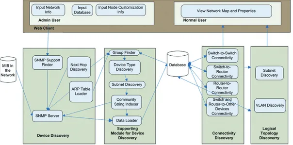
In this section we explain our system design. Figure 2 shows the overall architecture of the topology discovery system. This system follows the client–server software architecture. The client is a web client. The administrator or normal user can give inputs to the server module and the server provides the topology to the client for viewing. The administrator can customize certain devices using the customization module. The basic customizations that the administrator can conduct are changing the location, vendor, purpose, or type of device.
The server of a topology discovery system contains four main modules. The first module—device discovery—uses next hop discovery and an ARP table loader to retrieve the devices in the network; the SNMP server is responsible for sending SNMP queries to clients and handling concurrent responses. This is implemented based on a threading mechanism, to enable the simultaneous handling of multiple requests and responses. The second module is the supporting module for device discovery; this module helps the device discovery mechanism by grouping the discovered device based on multiple IP addresses for a single device. This module also discovers device type and based on device type it loads the SNMP MIB modules for the device in the database. The third module—the connectivity discovery module—discovers connectivity among devices; it takes its input from the database where we stored the relevant MIB modules for each device. The connectivity discovery module is divided into four smaller modules, for discovering switch-to-switch, switch-to-router, router-to-router, and switch and router-to-end host connectivity. The last module is the logical topology discovery module, which is responsible for discovering subnet and VLAN topologies; it takes input from the database and uses a connectivity discovery algorithm to discover connectivity for each subnet and VLAN.
Figure 3 shows the internal data structure and relationship among the tables of the topology. All the fields in the database are mapped to the MIBs outlined in Table 1. A unique identifier for each discovered device is generated using the singleton classidentifier. Our program has only one instance of theidentifierclass, and this class is responsible for generating a unique key for each new device. The IP address is not used as an identifier, since there can be multiple IP addresses belonging to one device. For the devices supporting SNMP, MIB modules such assystem,iftable,ipRouteTable,ipAddrTable,
ipNetToMediaTable,vtpVlanState, anddot1dBrige(see Table 1) are stored in the appropriate database
tables, as shown in Figure 3. IP address, forwarding info, sysService, and sysDesc are stored in
IPTable. InRouteTable, the next hop information is stored. The multiple addresses belonging to a
device, such as the router and switch for each subnet, are stored inAddressTable. InInterfaceTable, we store the information about the interfaces—which are also called ports—of the switches and routers.
Each interface of the device also has a physical address, anifIndex, and an interface description. When we find the connectivity between the devices, we also find the interface-to-interface connectivity between the devices supporting Bridge-MIB.NetToMediaTablestores the device lists that are reach-able from the node; it also stores the mapping of the physical address with the IP address.
BridgeMIBtablestores the Bridge-MIBs of all the L2 devices.VlanTableis an optional table; if the
network comprises devices other than Cisco, then we use this table to calculate the VLAN and the spanning tree associated with the VLAN. Once we update the database with all the device information, we start finding the connectivity and build theConnectivityTable, which is our output table that helps generate topology views.
4. IMPLEMENTATION AND EVALUATION
In this section we present the implementation details and describe functionality and views of our system; we will also evaluate our system compared to other research work. We used Advent Net Java APIs [11] for the SNMP library. These APIs offer a comprehensive development tool kit for SNMP-based network management applications. An important aspect of the discovery tool is the ability to view a network map; thus JGraphT [8], a free Java graph library that provides mathematical graph-theory objects and algorithms, is used.
We provided various types of abstraction of the network view, and each abstraction is implemented by each menu in our system. There are four main menus:List View,Tree View,Graph View, andVLAN View. There are three submenus:Device View,All Device View, andSubnet ViewunderTree Viewand
Graph View. Also, there are two submenus:Switch,VLANandVLAN,SwitchunderVLAN View.
Graph viewandTree vieware used in combination: the graph module shows connectivity among L3
devices, and once we click on the L3 device in graph, the detailed L2- and lower-level devices are shown in tree format in the next frame. Since there can be cycles in the L3-level connectivity, the connectivity cannot be shown using the tree. When we click on the nodes in the graph, the tree attached to each node of the graph can be seen in the next frame. Since the L2 devices support the spanning tree, there will consequently be no loop at this level, and we can show this level connectivity with a tree form. Figure 4 shows a graph view of the L3 devices in the left frame and a tree view of the L2 devices in the right frame. Showing the connectivity in tree form has various advantages, including the ability
to expand and contract the nodes and see the network hierarchy. Moreover, showing all the devices of the network in one layout is difficult, so this level of abstraction helps in viewing network connectivity. After double-clicking on each device, various properties of the device, such as device IP addresses, sysServices, forwarding info, system description, the support of different network layers, multiple subnets that a given device belongs to, interface details, the connectivity details of each interface, and some administrator custom entries can be viewed in a separate window. We can view the same window in the right frame of Figure 5.
Figures 5 and 6 show the subnet view and VLAN view, respectively. The left frame lists all the subnets and VLANS available in the network. The next frame shows the connectivity among the devices of the subnet and VLAN in the tree view. Subnet and the VLAN views are significant as they show the logical abstraction of the network.
Now we will explain results retrieved after running our algorithm on different networks. We applied our system to two different enterprise networks: POSTECH and Korea University. Using our tool we found that in Korea University there are total of 2019 devices, including 14 routers and L3 switches, 29 L2 switches, five L4 switches, 42 subnets, and 28 VLANs. In POSTECH we found a total of 7495 devices, including 522 L2 switches, eight routers, 76 L3 switches, five L4 switches, 208 subnets, and 149 VLANs.
The SNMP mechanism with an ARP cache table (NetToMediaTable) is used in our methods to discover the devices. We loaded the ARP cache of all the routers and switches; in this way, we were able to discover almost all the devices on the network. We noticed that the numbers of L2/L3/L4/L7 switches, routers, subnets, and VLANs discovered in multiple tests were the same, but that the number of discovered end hosts varied, with an error range of 1–2%. The cause of this error is the ARP cache table, which also contains inactive devices; furthermore, the entries in the ARP cache are not aged out, so in those situations some extra devices were discovered. We verified our results with the actual data existing with the POSTECH network administrators, and we found that we discovered 99% of the devices correctly; however, there was a 1% error of extra devices, i.e., those that were no longer active. In the case of connectivity discovery among the devices, there were many L2 switches—such as BlackDiamond switches [19]—that do not support SNMP. For such devices, we could not discover the connectivity.
We introduced a thread mechanism for resource discovery with the ARP cache module, as this module consumes most of the time. In this module, theNetToMediatable for routers and switches are retrieved and snmpget message is sent to each device in the NetToMedia table. Scalability testing shows a normal linear trend: if the number of devices increases, then the amount of time taken to discover the device also increases linearly. This trend can be seen in Figure 7 for POSTECH and in Figure 8 for Korea University. We recorded the time taken for discovering 100 devices, and then increased the number of devices by 200, 300, and 400 to 7000. However, some packet loss was found if we increased the number of threads in this process, which primarily depend on the processing power of the machine, bandwidth, and the underlying SNMP server implementation. Our code works well Figure 5. Subnet view, showing list of subnets, connectivity among devices in subnet and properties
of the device.
Figure 6. VLAN view, showing list of VLANs, devices in VLANs and connectivity among the devices.
with 10 simultaneous threads. Time-out for the snmpgetrequest was set to 5 seconds for the tests shown in Figures 7 and 8. By reducing the time out to 3 and 1 seconds the overall time of execution was reduced by 34% and 55%, respectively.
After running our tests several times we made various conclusions, and compared the benefits of our work with the current state of the art. Table 2 shows a comparison of previous research with the proposed method and explains the benefits of our algorithm. We utilized the SNMP mechanism to discover devices and connectivity; therefore, our algorithms are faster and generate less traffic. In terms of completeness, we discovered many type of devices, and also discovered connectivity among those devices in efficient ways. Using single-thread and 1-second SNMP time-out, discovering 7495 devices takes approximately 5 hours. Using 10 threads it takes 50 minutes. Connectivity discovery for 7495 devices only took 10 minutes 40 seconds. We discovered VLANs and subnet connectivity, which provides us with a logical view of the network. Our experiments were done on large networks with thousands of devices, and hundreds of VLAN and subnets.
5. CONCLUSION AND FUTURE WORK
In this paper, we extended the work of others by introducing a heuristic-based algorithm to connect the end host with a network and showing logical (subnet and VLAN level topology) as well as physical topologies. We discovered different types of devices, including routers, L2/L3/L4/L7 switches, print-ers, MIB-enabled devices and end hosts, and enhanced the already existing technique of device type discovery. We utilized the SNMP mechanism, which is the most efficient and generates the least amount of traffic in comparison to mechanisms in previous research. Our work can act as a guideline for implementing an SNMP-based topology discovery system. Our extensive tests are significant in terms of efficiency and the number of devices discovered. This work can be extended by integrating it with weather maps or monitoring tools to provide greater management functionality. Our future goals include integrating more link characteristics—such as link capacity and mean delay—to the links, and discovering connectivity for the L2 switches, such as the BlackDiamond switch, which does not support SNMP. For greater accuracy, our end host connectivity algorithm needs more refinement. We also plan to find a way to reduce the discovery and connectivity time. We aim to acquire a mechanism to perform fast topology update functionality as well. Various analyses of changes to topology will also be done in the future, which could help us discover the growth patterns of networks.
Figure 7. Threaded discovery of POSTECH. Figure 8. Threaded discovery of Korea University.
ACKNOWLEDGEMENTS
This work was supported in part by the IT R&D program of MKE/KEIT (KI003594, Novel Study on Highly Manageable Network and Service Architecture for New Generation) and by the WCU (World Class University) program through National Research Foundation of Korea funded by the Ministry of Education, Science and Technology (R31-2008-000-10100-0).
REFERENCES
1. Siamwalla R, Sharma R, Keshav S.Discovering internet topology. Technical report, Cornell University, May 1999. 2. Breitbart Y, Garofalakis M, Jai B, Martin C, Rastogi R, Silberschatz A. Topology discovery in heterogeneous IP networks:
the NetInventory system.IEEE/ACM Transactions on Networking2004;12(3): 401–414.
3. Lowekamp B, O’Hallaron DR, Gross TR. Topology discovery for large Ethernet networks. InACM SIGCOMM, San Diego, CA, August 2001; 237–248.
4. Nazir F, Tarar TH, Javed F, Suguri H, Ahmad HF, Ali A. Constella: a complete IP network topology discovery solution. In APNOMS 2007, Sapporo, Hokkaido, Japan, October 2007; 425–436.
5. Cisco. How to get dynamic CAM entries (CAM table) for catalyst switches using SNMP. http://www.cisco.com/en/US/ tech/tk648/tk362/technologies_tech_note09186a0080094a9b.shtml [12 June 2010].
6. Cisco. SNMP community string indexing. http://www.cisco.com/en/US/tech/tk648/tk362/technologies_tech_ note09186a00801576ff.shtml [12 June 2010].
7. CISCO-VTP-MIB. http://www.cisco.com/en/US/tech/tk648/tk362/technologies_tech_note09186a00801576ff.shtml [12 June 2010].
8. JGraphT. Implementation and source code. http://jgrapht.sourceforge.net/ [12 June 2010]. 9. Bierman A, Jones K. Physical topology MIB.IETF RFC-2922, September 2000.
10. Bobelin L, Muntean T. Algorithms for Network Topology Discovery using End-to-End Measurements. In Proceedings of the 2008 International Symposium on Parallel and Distributed Computing, 2008: 267–274.
11. AdventNet. AdventNet SNMP API. http://snmp.adventnet.com/ [12 June 2010].
12. McCloghrie K, Rose M. Management information base for network management of TCP/IP-based Internets, MIB-II.IETF RFC 1213, March 1991.
13. Decker E, Langille P, Rijsinghani A, McCloghrie K. Bridge MIB.IETF RFC 1493, July 1993.
14. Bell E, Smith A, Langille P, Rijsinghani A, McCloghrie K. Q-BRIDGE-MIB.IETF RFC 2674, August 1999.
15. Case J, Fedor M, Schoffstall M, Davin J. A Simple Network Management Protocol (SNMP).IETF RFC-1157, May 1990. 16. Passmore D, Freeman J. The virtual LAN technology report. http://www.3com.com/nsc/200374.html [12 June 2010]. 17. IEEE 802.1Q.IEEE Standard for Local and Metropolitan Area Networks: Virtual Bridge Local Area Networks, 1998. 18. Donnet B, Friedman T. Internet topology discovery: a survey.IEEE Communications Surveys and Tutorials2007;9(4):
56–69.
Table 2. Comparison of network topology discovery methods. Siamwallaet al.
(1999) [1]
Lowekampet al. (2001) [3]
Breitbartet al.
(2004) [2] Nazir (2007) [4] Proposed method Method Ping/broadcast ping/traceroute/ zone transfer DSN server/ SNMP/subnet guessing algorithm SNMP SNMP (ICMP spoofing/ heuristics) SNMP/ping Only SNMP Types of devices discovered
Routers/hosts L2 devices, hubs, dumb devices Routers/L2 switches/ hosts Router/L2, L3 switches/ hosts/printers Router/L2, L3, L4, L7 switches/ printers/hosts/MIB enabled devices Subnet/ inter-subnet connectivity Subnet guessing algorithms; heuristics; no inter-subnet connectivity
Not supported Inter-subnet connection, complicated formulas Intelligent subnet-guessing algorithms Subnet map; inter-subnet connectivity VLAN discovery
Not supported Not supported Complex formulae for VLAN connectivity
Not supported VLAN supported; Switch→VLAN and VLAN→ Switch map Performance Compares performance
of SNMP, ping, traceroute etc.; SNMP performs best No significant performance data
ICMP spoofing and calculating AFT table at frequent intervals takes a long time No significant performance data 7000 nodes discovered
19. Extreme Networks. BlackDiamond core switching products. http://www.extremenetworks.com/products/switching-core-family.aspx/ [6–30 June 2010].
20. Product specific MIB, http://www.cisco.com/public/sw-center/netmgmt/cmtk/mibs.shtml/.
21. Plummer DC. An Ethernet address resolution protocol or converting network protocol addresses to 48.bit Ethernet address for transmission on Ethernet hardware.IETF RFC 826, November 1982.
22. Mockapetris P. Domain names: concepts and facilities.IETF RFC 1034, November 1987.
23. Torren M. tcptraceroute: a Traceroute implementation using TCP packets. UNIX man page (2001). http://michael.toren.net/ code/tcptraceroute/ [12 June 2010].
24. Sung Y, Rao S, Xie G, Maltz D. Towards systematic design of enterprise networks.ACM CoNEXT, August 2008. 25. Bejerano Y. Taking the skeletons out of the closets: a simple and efficient topology discovery scheme for large Ethernet.
IEEE INFOCOM, April 2006; 1–13.
26. Wood DCM, Coleman SS, Schwartz MF. Fremont: a system for discovering network characteristics and problems. In Proceedings of Usenix Winer Conference, January 1993.
27. Carofalakis M, Rastogi R. Data mining meets network management: the Nemesis project.ACM SIGMOD International Workshop on Research Issues in Data Mining and Knowledge Discovery, May 2001.
AUTHORS’ BIOGRAPHIES
Suman Pandeyis a researcher in Computer Science and Engineering department at POSTECH. She received her M.S. from POSTECH, Korea in August 2009. Her research interests include topology discovery and management, IPTV deployment and machine to machine network management.
Mi-Jung Choiis an assistant professor in the Department of Computer Science, Kangwon National University, Korea. She received her B.S. degree in CS from Ewha Womans University in 1998, and M.S. and Ph.D. degrees from the Dept. of CSE at POSTECH in 2000 and 2004, respectively. Her research interests include traffic measurement, and future Internet management.
Young J. Wonis a postdoctoral researcher at INRIA, France. He received B. Math (2003) from the University of Waterloo, Canada, and M.S. (2006) and Ph.D. (2010) from POSTECH, Korea.
James Won-Ki Hongis Professor and Head of Division of IT Convergence Engineering and Dean of Graduate School for Information Technology, POSTECH, Korea. He received a Ph.D. degree from the University of Waterloo, Canada in 1991. His research interests include network management, network monitoring and analysis, ubiquitous computing and convergence engineering. James has served as Technical Chair (1998–2000), Vice Chair (2003–2005) and Chair (2005–2009) for IEEE Comsoc Committee on Network Operations and Manage-ment (CNOM). He is serving as Director of Online Content for the IEEE Comsoc. He is a NOMS/IM Steering Committee Member and a Steering Committee Member of APNOMS. He was a General Co-Chair of 2010 IEEE/IFIP Network Operations and Management Symposium (NOMS 2010). He is an editorial board member of IEEE TNSM, JNSM, IJNM, JCN and JTM.