Design and Development of a Prototype for Illuminating a Smart
Home using a Client-Server Application
Mario Ciau
†, Jesús Acevedo
†, Raciel Poot
†, Victor Chi
†, Lizzie Narváez
†and Erika Llanes
††UADY, Unidad Multidisciplinaria Tizimín
Summary
This project presents the design and development of a prototype for controlling the illumination and security of a smart home through the use of a client–server network model. For this we developed an application in Visual Basic for the client–server communication using TCP/IP network protocol.
Key words:
Domotics, Client-Server Model, Relay, Chip mc74hc245an.
1. Introduction
These days living in a smart home allows us to carry out daily activities more easily making day to day life more comfortable for the members of a family; we can do this by automating our domestic activities using the technology which is currently at our disposal.
Smart homes allow us to carry out daily activities such as: turning lights on and off, checking whether doors and windows are open or closed, turning on appliances remotely to prepare breakfast, etc. All of which helps to offer the inhabitants better living conditions.
Thanks to the impact that smart homes have had in the automation of buildings, wired and wireless communication technologies have been created with the aim of aiding interaction between household devices [1]. New technology - perhaps first conceived to help disabled people with mobility and security, to reduce energy consumption or simply to offer comfort- has come along to offer us the benefits of a smart home, which were previously only available to those with sufficient spending power but which in the near future will be available to low-income households thanks to the diminishing costs of smart devices brought about largely by current research projects.
In this project we will explain the design and development of a prototype to simulate a smart home controlled via a computer using the software which in turn controls the hardware, connected via a parallel cable to the computer. In this case, we determined the functions that needed to be automated during the building of the hardware; and with regard to the software development we programmed a client-server application to permit a connection of this type via TCP/IP protocol. With this application two computers
were connection: one with the role of server and other with the role of client. From the client orders were sent (for example, to turn on a light) which are then interpreted and carried out by the server. Finally we built a scale model of the smart home and in conjunction with the hardware and software we were able to perform our simulation tests.
2. Background
The first attempt at normalization of home automation or “domotics”, date back to the early eighties in Japan: the introduction of domotics was part of a strategy to renovate the electricity sector by reducing energy consumption in the midst of an industry crisis.
The US were the first country to promote and recommend the development of domotics through the “Smart House” project directed by NAHB (National Association of Home Builders) started in 1984 with the objective of uniting in one single wire the different wires used within the home [2].
In Europe, the first efforts at normalization started in 1985 with the support of the EUREKA programme. The project, entitled Integrated Home Systems, brought together the seven market-leading electronics companies with the aim of creating a domestic network with mutually compatible functionality [2].
Following on from these first two pioneering projects, came a Japanese project called HBS (Home Bus System), this idea for a domestic bus was presented in 1987 and it’s development was the result of partnership between various manufacturers coordinated by the Industry and International Trade Ministries. In Europe, in 1989, the Home Systems projects was created, within the ESPRIT programme (European Strategic Programme for Research and Developments of Information Technology), the aim was to continue with the work started during the EUREKA programme in order to obtain a standard which would encourage evolution towards integrated household applications.
After these initial international projects, many national and international companies have become interested in this sector which has enormous future potential and large scale investments have been made in related technologies. All
this has helped domotics to shed its futuristic sci-fi image and become a practical reality [3] [4].
3. Domotics
Domotics is a combination of elements which, once installed, connected and controlled automatically within a dwelling, free the user from daily chores and provide at the same time optimum comfort, energy efficiency, safety and communication [5].
When considering domotics, it’s necessary to conceptualize the completely integrated control of electrical and electronic devices and appliances in a building. This can be done through interior or exterior communication networks, either wired or wireless. These devices can be managed physically or remotely. Which is why domotics can not only be controlled in the home in real time, but can also be programmed remotely any number of hours in advance.
The service that domotics provides can be grouped into five distinct categories [6]:
Energy efficiency: Saving energy is not a tangible function but rather an effect which can be achieved in several ways. In many cases it’s not necessary to replace domestic products and systems with others that consume less energy, but instead to better manage the use of existing devices. - Climate control: programming and zoning.
- Electricity management:
• Intelligent rationing of electrical consumption: disconnection of non-priority equipment and automatic shutdown when not in use.
• Tariff management, automated and strategic use of appliances to coincide with low-cost, off-peak energy tariffs.
Comfort: Including all actions than can improve domestic comfort levels, be they passive, active or a combination of both, for example:
- Illumination:
• Automatic switching-off of all lighting in the household.
• Automated on/off settings for each lighting point in the house.
• Regulation of home lighting levels in accordance with natural ambient light levels.
- Automation of all domestic systems, installations and equipment offering efficient control and easy handling. - Control via internet.
- Multimedia and home leisure management.
Security: This consists of a home security network responsible for protecting the residents and their belongings.
- Simulated presence of residents.
- Warning systems for fires, gas leaks, water leaks and carbon monoxide concentration in car ports etc.
- Medical alarm and phone-assistance. - Automated control of blinds and curtains. - IP camera access.
Communication: The management of domestic communication systems and infrastructure.
- Remote control using the internet, PC or handheld remote.
- Alarm transmission. - Intercommunication.
Telemanagement and Accessibility: Design for all, an accessible design to cater for the full range of user diversity and engender social inclusion end equality. This focus area constitutes an ethical and creative challenge whereby disabled or physically impaired individuals might be able to gain access to new technology without fear of obstacles created through inadequate technology or inconsiderate architecture.
4. Project setting
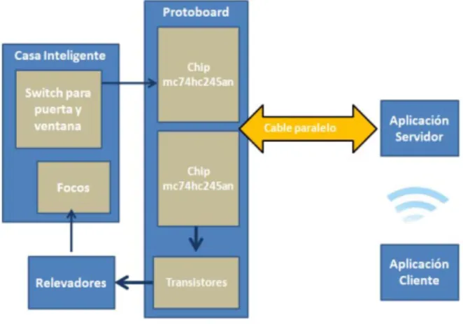
The setting designed and developed for this project is similar to the block structure shown in figure 1.
Fig. 1. System architecture.
4.1 Client-Server Model
With regard to the communication between the modules known as “server application” and “client application”, we used the client-server model. In this model, the device that requests information is named client and the device that responds to the request is named server [7].
A server is generally a computer containing information to be shared with multiple client systems. A client, on the other hand, is a device which will make use of the services contained within the server.
The client sends a request to the server through its IP address and the port which is reserved for the particular service performed by the server. The combination of the
port number and the IP address assigned to the host exclusively identifies a given process that is performed by a specific host.
Some of the main characteristics of using a client-server model as follows:
- The server presents all its clients with a unique and well defines interface.
- The client needn’t be familiar with the server’s logic, only with its external interface.
- The client doesn’t depend on the physical location of the server, nor on the type of machine in which it is housed, nor on its operating system.
The client computer is used to send to the server some of the following commands:
- Turn on lamp 1. - Turn on lamp 2. - Turn on lamp 3. - Turn on all lamps. - Turn off all lamps.
In terms of security, the client computer is used to determine the state of the doors and windows, to check if they are open or closed.
The computer used as a server will process the orders received from the client using the software developed in this project, and by means of a parallel cable it will communicate with the prototype designed and developed in this project to turn on the lights in the house or determine whether a window or door is open or closed. The connection of the devices used as client and server is achieved via the server port and an IP address, this by means of software created in this project.
4.2 Design of the Smart Home
The design of the smart home used in this project consisted of building a scale model with two rooms, a main door and a window, as can be seen in figure 2.
Fig. 2 Design of the home.
Three lamps were installed in the interior of the house using three 30 watts bulbs, as well as sensor switches on the door and the window to determine if these are open or
closed. The bulbs in the house are connected to the relays and the switches with the mc74hc245an chip. The relays
and the chip are described in the following section.
5. Design and development of the prototype
The design and development of the prototype consisted of the construction of the hardware in the protoboard for which we required the following components:- 3 single pole/double throw relays, - 3 transistors (type 131),
- 6 resistors (4 x 1 kΩ and 2 x 3201 Ω), - 1 parallel cables (type DB25) and - 2 chips (type mc74hc245a).
The hardware for this project was started by cutting one end of the parallel cable to extract each of its interior cables. Later, with a multimeter, we identified the interior cable of each pin of the parallel port, these were numbered, and then we established which cable belonged to which byte in the parallel port. Next we identified these pins on the protoboard following the diagram shown in figure 3, which shows exactly which byte to assign to which chip.
Fig. 3 Schematic diagram to connect the parallel port to the chip mc74hc245an.
Figure 4 shows the diagram which illustrates how to use the three parallel port bytes: data, state and control.
Fig. 4 Parallel port.
The mc74hc245an chips can be used as data “in” or “out” by setting pin one to 5 volts or 0 volts respectively. Continuing with the construction of the prototype we proceeded to set the rest of the components on the protoboard, we connected the transistors according to their configuration (base, collector and sender) with 1 kΩ resistors of, the relays and the chip to be used for input. The relays were connected to the bulbs given that they will be working as interrupters.
We connected the parallel port data byte to the mc74hc245an chip so that the voltage arriving from each pin would increase upon passing through it. Likewise the outputs of the chips were connected to the transistors so that they also increase in voltage, activating the relays which would act as interrupters to turn on and turn off the lamps.
We also connected the “state” byte to the other chip configured for output taking into account that the outputs of this chip were not connected to the transistors but instead to one end of each foot of each switch with a “pull-up” resistor to determine whether the door or window was open or closed. This was achieved by reading the logic values that were being sent, that is, with the “pull-up” resistor that we used the normal input to the chip was 5 volts because the switch is open. This meant that the door or window was open and when the switch closed input to the chip the voltage became 0 volts which meant that the door or window was closed.
5.1 Relay
We decided to use the relay in the building of the prototype to facilitate the control of a device from a distance; the relay can be activated with little current, however, it can also activate large machines that consume large amounts of current and, in addition, several relays at a time can be controlled with just one control signal. A relay can be defined as a device that controls the state of an interrupter, it is activated and deactivated when its electromagnet is energized, in other words when it needs to receive voltage in order to function [8].
The voltage supply causes a connection or lack of connection between two or more terminals of a device.
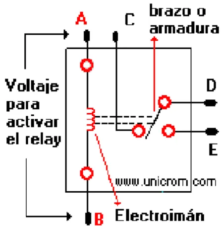
This connection happens thanks to the repulsion or attraction of a small arm by the electromagnet. This arm connects or disconnects the aforementioned terminals. The relay functions in the following way: if the electromagnet is activated it pulls the arm and connects points C and D. If the electromagnet is deactivated, it connects points D and E (see figure 5).
Fig. 5 Relay.
In this way you can connect one thing when the electromagnet is active and another when it is inactive. It is important to know the resistance of the electromagnet’s coil (between terminals A and B) that activates the relay and therefore what voltage is required to activate it, because the voltage and resistance inform us of the strength of signal required to activate the relay and the amount of current that should be supplied.
5.2 The mc74hc245an chip
This chip was used to increase the voltage that leaves through the parallel port, in other words, low voltage is boosted upon passing through the chip. It also has a pin that indicates the direction of data-flow, be it from the chip to the parallel port or vice-versa, this is how we obtained the writing and reading of data.
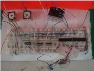
Using the chip was essential because the parallel port only manages 20mA current in all its pins, which is only enough current to power a single LED diode, relays require much more. For this reason the chip injects extra energy into the parallel port, and in consequence, activates the transistors which in turn trigger the relays. In addition, this chip transmits parallel data, in 8bit bursts, and is bidirectional, a characteristic which proves important for our project as our data is written in one direction and read in the other. Another important feature is its low cost. All of these characteristics informed us in our selection [9]. After connecting all these components we had the prototype (hardware) shown in figure 6.
Fig. 6 Prototype system.
Once finished building the prototype we directed out attentions to the application.
6. Software development
With regard to the application, we used the Visual Basic programming language because it offers users a friendlier environment in terms of graphics creation, and also due to its having the Winsock component which lets us easily implement communications using the TCP/IP network protocol.
The main properties, methods and events used by this component and during its programming are:
Properties:
- LocalPort: this establishes which port is to be set to “listen” when in server mode.
- Remoteport: this establishes which port is to be connected when in client mode.
Methods:
- Listen: Sets the local port to listen for a connection request.
- Accept: Accepts a connection request. - GetData: Obtains data via a connection. - SendData: Sends data via a connection.
Events:
- ConnectionRequest: This is produced when a client requests a server connection.
- Connect: This is produced when a local PC is connected to a remote machine.
- Close: This is produced when the remote machine closes the connection.
- DataArrival: This is produced when the sent data arrives via the connection.
Figure 7 shows the start windows (in design mode) that will be presented in the client and server computers respectively.
Fig. 7 Screens application startup.
What follows is an extract of the client code, to carry out the following commands: connect (client to server), disconnect and send (orders for the bulbs and door and window positions).
The following extract of code represents some of the functions that the server carries out, the same functions that will be employed every time the client sends a petition. In this case, the server will search within the established functions and if there is a match it will proceed to execute it, for example if the client send the request “turn on lights”, the server will search for the function and carry it out, in this case by sending binary data through the parallel port to the hardware, which interprets the 1 logic as 5 volts and the 0 logic as 0 volts, thereby turning on the lights in the house.
To enable the parallel port and to carry out the reading and writing of data we created a module with the following lines of code:
It´s worth mentioning that for the program to work correctly it is necessary to have the io.dll library in the System 32 folder, which is essential in order to send data through the parallel port. This is important because the programming language does not have its own routines for sending data.
7. Test and results
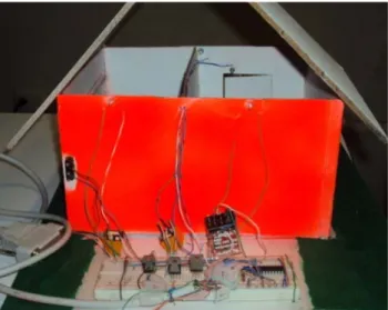
Upon finishing construction of the prototype we proceeded to join the prototype to the scale model of the house, as can be observed in figure 8.
Fig. 8 Prototype connected to the smart home.
Afterwards we began testing. Firstly we tested the hardware using a power source to supply voltage and we checked that there was continuity between the components using the multimeter to be sure that the protoboard was functioning correctly. Upon finding no continuity problems we proceeded to test the circuit in order to check its functionality; for this we sent voltage through the circuit and observed that all the bulbs illuminated correctly. For the software testing we firstly checked the connection between computers in order for them to be able to send requests, then we connected the hardware (already tested) via the parallel port to the computer in the role of server. We ran the software on the client device and on the server to send requests and confirm that the server was reacting correctly.
It can be observed in figure 9 that all lamps in the house turn on when the order is sent from the client to the server.
8. Conclusions
This project presents the design and construction of a hardware prototype and the design of a client server application in the Visual Basic programming language, to control the illumination and security of a model of a smart home.
It also presents a description of the tests carried out to ensure the correct functioning of the components used in the system´s architecture.
The activities carried out in the smart home consisted of the turning on and off of bulbs both independently and in groups, as well as the inspection of the state (open or closed) of the door or window of the house; further functions would be added later. This project has taught us that we can work wonders with the technology currently at our disposal, but we can also achieve things without needing the latest technology.
Finally, the development of this project allowed the team of university staff to work in a multidisciplinary fashion, and at the same time allowed the students involved in the project to put into practice knowledge relating to computer networks, programming, software engineering and electronics that they had acquired from their computer science degree courses.
References
[1] Reinoso Pérez, Esteban Santiago. Diseño e implementación de un prototipo para una red de domótica y seguridad para un hogar utilizando el estándar IEEE 802.15.4 “Zigbee”. Artículo presentado en las XXII Jornadas en Ingeniería eléctrica y electrónica. 2009.
[2] Galeana Meneses, M. A. Sistema de procesamiento de información multimedial aplicado a Domótica. Tesis de Maestría en Ciencias con especialidad en Ingeniería en Sistemas Computacionales. Departamento de Computación, Electrónica, Física e Innovación, Escuela de Ingeniería y Ciencias, Universidad de las Américas Puebla. Mayo 2007. Universidad de las Américas Puebla. Disponible en http://catarina.udlap.mx/u_dl_a/tales/documentos/mesp/galea na_m_ma/capitulo1.pdf
[3] Escobar P. Alex. Edificios inteligentes y casa domóticas. Publicado en noviembre, 2000. Disponible en http://www.monografias.com/trabajos5/edin/edin.shtml?mon osearch
[4] Huidobro, J. Edificios inteligentes y domótica. Publicado en
diciembre, 2003. Disponible en http://www.monografias.com/trabajos14/domotica/domotica.
shtml?monosearch.
[5] Ruiz, J.M.; Bravo J.; y Ortega M. "Domótica". Revista de Enseñanza y Tecnología. 1995. 4, 46 - 48.
[6] http://es.wikipedia.org/wiki/Dom%C3%B3tica. Última modificación 30 de julio de 2010.
[7] Dye, Mark A.; McDonald, Rick; Rufi, Antoon W. Aspectos básicos de networking. Pearson Education. 2008.
[8] El relevador: partes y funcionamiento. Electrónica Unicrom.
2002-10. Disponible en http://www.unicrom.com/Tut_relay.asp.
[9] Jan, Axelson. Parallel Port Complete: Programming, Interfacing & Using the PC’S Parallel Printer Port. Editorial Investigación Lakeview. 1997-02.
Mario Antonio Ciau Uitzil
[[email protected]] currently a student at the Faculty of Mathematics at the Autonomous University of Yucatan – Multidisciplinary Unit Tizimín. Participated in the project fair presentation of this project in conjunction with Jesús Acevedo.
Jesús Alejandro Acevedo Niño
[[email protected]] currently a student of 7th semester of the Bachelor of Computing Faculty of Mathematics belonging to the Autonomous University of Yucatan in the Multidisciplinary Unit Tizimín. Participated in the project fair presentation of this project in conjunction with Mario Ciau.
Raciel Omar Poot Jiménez
[[email protected]] received a degree in Computer Engineer from the Autonomous University of Yucatan (UADY) in 2008. He has been a full time teacher at the Autonomous University of Yucatan since 2008 at the department of electronics in Tizimín México. He has participated in development projects of electronic engineering. Currently is giving courses on electronic interfaces and programming languages in the professional programs at the UADY.
Victor Manuel Chi Pech
[[email protected]] obtained his degree in Computer Science from the Autonomous University of Yucatan (UADY) in 1996 and his M. Sc. degree in Wireless Network from Monterrey Technological Institute (ITESM), Campus Cuernavaca, in 2007.
Victor Chi has worked since 2000 at the Autonomous University of Yucatan, as a full time professor. He has participated in software engineering development projects. He is currently giving courses on wireless networks and software engineering in the professional programs in the UADY.
Lizzie Edmea Narváez Díaz
[[email protected]] received a degree in Computer Science from the the Autonomous University of Yucatán (UADY) in 1997. She received a Master of Computer Science degree from Monterrey Technological Institute (ITESM), Campus Cuernavaca, in 2007.
She has been a full time teacher at the Autonomous University of Yucatán since 2000 in the Networking department in Tizimín México. She has participated in software engineering development projects. Currently she is giving courses on wireless networks in the professional programs in the UADY.
Erika Rossana Llanes Castro
[[email protected]] received a degree in Computer Science from the Autonomous University of Yucatan (UADY) in 2002. She is about to receive a Computer Science degree from Monterrey Technological Institute (ITESM), Campus Estado de Mexico.
Currently, she is a full time academic technician at the Autonomous University of Yucatan since 2002 in the department of computer in Tizimín México. She has participated in software engineering development projects. Currently is giving courses on programming mobile devices in the professional programs in the UADY.