Institute of Architecture of Application Systems University of Stuttgart
Universitätsstraße 38 D–70569 Stuttgart
Masterarbeit Nr. MCS-0016
Deployment of TOSCA Cloud
Services Archives using
Kubernetes
Md. Rezzakul Haider
Course of Study: Computer Science
Examiner: Prof. Dr. Dr. h. c. Frank Leymann Supervisor: Dipl. -Inf. Johannes Wettinger
Commenced: October 2, 2016 Completed: March 22, 2017
Abstract
In recent years container virtualization and container management emerged in the context of Cloud computing as a new paradigm in IT enterprises. It introduces new approaches that enable the IT industry to manage their application and services more effectively in the Cloud. With the rapid increase of usage of Cloud computing, IT companies introduce new tools to manage their applications in Cloud environments. However, each tool has its own kind of definitions and specifications on describing the applications in their platforms which creates vendor lock-in for its users and also hampers the portability features of Cloud applications. To solve this issue, TOSCA has been introduced to the industry by OASIS. The Topology and Orchestration Specification for Cloud Applications (TOSCA) provides a standardization approach enabling portability of Cloud services between different Cloud Computing providers. The main goal of TOSCA is to model enterprise applications in a standardized and technology-independent way regardless of a specific Cloud provider or environment. To model and deploy applications using TOSCA properly, all required artifacts are packaged and bundled as TOSCA Cloud Service Archives (CSARs). Such CSARs are then used by Cloud orchestration engines to deploy the application to Cloud platforms. At the technology level, several deployment and cluster management approaches and tools are rapidly emerging such as Docker Compose, Docker Swarm, Kubernetes, Nomad, and Apache Mesos. Most of them are centered around containerization of middleware and application components.
The focus of this thesis is to provide mapping concepts of TOSCA application topologies to a container-based deployment and management approach. Since Kubernetes and Docker are the most prominent open-source solutions in this field, we specifically consider Kubernetes and Docker as part of the prototype implementation. To assess feasibility of the proposed approach and usability of the system, we also provide case studies based on a motivating scenario.
Keywords: TOSCA, Deployment Automation, Container Virtualization, Cloud Comput-ing, Docker, Kubernetes, Minikube.
Contents
1 Introduction 11
1.1 Motivation . . . 11
1.2 Objective . . . 12
1.3 Outline . . . 12
2 Fundamentals and Related Works 15 2.1 Deployment Automation . . . 15
2.2 Container Virtualization . . . 17
2.3 Topology and Orchestration Specification for Cloud Application . . . 19
2.3.1 TOSCA Syntax . . . 19 2.3.2 TOSCA Example . . . 23 2.4 Kubernetes . . . 25 2.5 Docker . . . 33 2.6 Related Works . . . 35 2.6.1 OpenTOSCA . . . 35 2.6.2 Cloudify . . . 37 2.6.3 OpenStack Heat . . . 38 3 Requirements 41 3.1 Mapping Goal . . . 41 3.2 Architecture Requirements . . . 41 3.2.1 Technical Requirements . . . 42 3.2.2 Non-Technical Requirements . . . 43 3.3 Supported Operations . . . 44 3.4 Supported Artifacts . . . 44
4 Architecture and Design 47 4.1 Concept of Mapping Techniques . . . 47
4.2 Assumptions . . . 48
4.3 Mapping Concept using TOSCA Definition Files . . . 50
4.3.1 Resolving Node Relationship . . . 53
5 Implementation and Evaluation 63
5.1 Overall System Design . . . 63
5.2 TOSCA Parser . . . 64
5.3 Generators . . . 66
5.3.1 Dockerfile Generator . . . 66
5.3.2 Kubernetes File Generator . . . 67
5.4 System Automation . . . 69
5.4.1 Docker Container Management Automation . . . 69
5.4.2 Minikube Provisioning Automation . . . 70
5.4.3 Kubernetes Deployment Automation . . . 71
5.5 Evaluation and Results . . . 71
5.5.1 Case Study with Containerized Node . . . 72
5.5.2 Case Study of TOSCA Application Node’s with Scripts . . . 77
6 Summary and Future Work 79
List of Abbreviations 81
List of Figures
1.1 Graphical Representation of an Application Topology . . . 12
2.1 VM vs Container Virtualization Design . . . 18
2.2 Diagram-TOSCA Template for a Simple Software Installation [TOSCA-Simple-Profile-YAML16] . . . 25
2.3 Simple Kubernetes Architecture Diagram [DO15] . . . 27
2.4 Example of Kubernetes Application Topology Based on [Gup16] . . . 32
2.5 Graphical Representation of Multi-Container Pod . . . 33
2.6 OpenTOSCA Ecosystem Overview . . . 35
2.7 OpenTOSCA Container Architecture . . . 36
2.8 Cloudify Architecture Overview . . . 37
2.9 Simplified Architecture Diagram of Heat-Translator . . . 39
3.1 Conceptual Architecture Diagram . . . 42
4.1 TOSCA to Kubernetes Mapping Concept Diagram . . . 47
4.2 TOSCA to Kubernetes Topology Mapping on Component Level . . . 53
4.3 "HostedOn" Relationship base Nodes Mapping to Dockerfile . . . 56
4.4 Mapping between TOSCA and Kubernetes Pods . . . 58
4.5 Mapping between TOSCA and Kubernetes Sevice . . . 59
4.6 Mapping of TOSCA "ConnectedTo" Relationship in Kubernetes . . . 60
5.1 Class Diagram of "toscaparser" Package . . . 63
5.2 Class Diagram of "cmd_response" Class . . . 64
5.3 Dockerfile Generator Interaction Model . . . 67
5.4 Minikube Dashboard for Monitoring . . . 71
5.5 Minikube Dashboard after Deployment . . . 76
5.6 Pods in Minikube Dashboard . . . 76
5.7 Deployed "wordpress" Application URL . . . 77
Listings
2.1 Syntax of TOSCA Service Template [TOSCA-Simple-Profile-YAML16] . . 20
2.2 Syntax of TOSCA Topology Template [TOSCA-Simple-Profile-YAML16] . 21 2.3 Example-TOSCA Template for a Simple Software Installation [TOSCA-Simple-Profile-YAML16] . . . 23
2.4 Example of Pod . . . 28
2.5 Example of Replication Controller . . . 29
2.6 Example of Service . . . 29
2.7 Example of Deployment . . . 31
2.8 Example of Multi-Container Pod Based on [kubernetes] . . . 32
3.1 Sample Dockerfile Snippet of a Redis Server [Docker] . . . 45
3.2 Sample Bash (.sh) Script . . . 45
4.1 ConnectedTo Relationship Syntax . . . 50
4.2 "kubernetes_metadata" Setup Syntax . . . 50
4.3 TOSCA Definition of Wordpress Application Based on [Openstack15] . . 50
4.4 Example of "host" Dependency in Node Template Based on [Openstack15] 54 4.5 Example of "Docker" Node Type in Node Template Based on [TOSCA-Simple-Profile-YAML16] . . . 55
4.6 Input key in Interface Operation . . . 57
4.7 Environment Variable in Kubernetes . . . 57
4.8 Connection Syntax of Pod . . . 61
5.1 Sample "mysql-database" Deployment File Generated by Deployment File Generator . . . 67
5.2 Sample "mysql-database" Service File Generated by Service File Generator 68 5.3 Docker Build Code Snippet . . . 69
5.4 Docker Push Code Snippet . . . 70
5.5 Minikube Start Code Snippet . . . 70
5.6 Minikube Dashboard Code Snippet . . . 70
5.7 Minikube Get URL Code Snippet . . . 70
5.8 Kubernetes Deployment Code Snippet . . . 71
5.12 Service File for "wordpress" Container . . . 75 5.13 Service File for "mysql-database" Container . . . 75 5.14 "wordpress" Dockerfile Generated by Dockerfile Generator . . . 78
1 Introduction
1.1 Motivation
In recent time, most of the modern applications are developed focusing on Cloud platform [MG+11] and existing application are migrated into Cloud [LFM+11]. In the IT industry there is a wide range of tools available to deploy applications in the Cloud. However, the industry still faces the problem while orchestrating this complex set of systems in the Cloud. Moreover, in order to maintain the dependencies between the applications in the Cloud there are still some difficulties. When this is the case, OASIS1
introduces a new solution to the Cloud community which is called TOSCA.
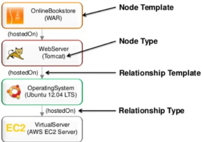
The OASIS Topology and Orchestration Specification for Cloud Applications (TOSCA) is a standardization effort that aims to align the definition, deployment and management of application topologies and corresponding plans in a technology-agnostic manner. Here the word "plan" refers to management plan which specify the operational management behavior of a Service Template. And "topology" refers to the structural description of the application and the components it consists of and the relationships among them. More details on TOSCA application topologies and management plan can be found in [BBKL14a]. Figure 1.1 represents the graphical example of an applicatoin topology. All required artifacts are packaged and bundled as TOSCA Cloud Service Archives (CSARs) in a self-contained manner. Such CSARs are then used by Cloud orchestration engines to deploy the application to Cloud platforms.
Figure 1.1:Graphical Representation of an Applicatoin Topology2
Nowadays, the technology world is more focused on container virtualization as it makes it more convenient to deploy application to Cloud platforms. At the technology level, several deployments and cluster management approaches and tools are rapidly emerging such as Docker Compose and Swarm, Kubernetes, Nomad, and Apache Mesos. Most of them are centered around containerization of middleware application components.
1.2 Objective
The goal of this thesis is to map the concepts of TOSCA application topologies (specified using the YAML-based TOSCA Simple Profile 1.0) to a container-based deployment and management approach. Diverse mapping alternatives are discussed and compared. Since Kubernetes is one of the most prominent open-source solutions in this field, this thesis specifically considers Kubernetes at the implementation level. Also Docker has been considered to containerize applications in this thesis.
1.3 Outline
The remainder of this document is organized into the following chapters:
2
1.3 Outline
Chapter 2 – Fundamentals and Related Works: In this chapter, the fundamental con-cepts and an overview of the related works that are essential to understand the work are provided.
Chapter 3 – Requirements: In this chapter, the abstract mapping goal and a detailed requirement analysis of system architecture has been provided.
Chapter 4 – Architecture and Design: This chapter provides a brief discussion on mapping concept between TOSCA and Kubernetes. Also the assumptions have been discussed in this chapter.
Chapter 5 – Implementation and Evaluation: This chapter discusses implementation details of the system with a brief discussion on each component. Also the evaluation process of the system has been discussed with different case studies.
Chapter 6 – Summary and Future Work: This chapter summarizes the results of this thesis work and draws a conclusion. It also throws some light on the future work to be extended based on this work.
2 Fundamentals and Related Works
This chapter provides an overview of the fundamental concepts needed to build a foundation for the purpose of the thesis. These are key to understand the concepts presented in this thesis. References are included for better clarity of the main topics.
2.1 Deployment Automation
Continuous delivery [HF10] appeared as a useful solution to bridge the gap between developer and operational parties, this collaboration approach between development and operations is often termed as DevOps [Hüt12]. As DevOps focuses on improving the software release cycles, hence automated deployment plays an important role in continuous delivery. Deployment automation enables applications to be deployed across the different environments used in the development process, as well as in the final production environments.
Cloud computing [MG+11], [LF09] appeared as unquestionable IT phenomena in recent times. Nowadays applications are developed focusing on Cloud, that means applica-tions are developed as Cloud-native applicaapplica-tions [Wil12] or the existing applicaapplica-tions are moved into the Cloud [LFM+11], [BLS11]. Hence, one of the most important requirements to make use of the Cloud computing is fully automated deployment of applications [WGL14].
Nowadays, there are different kinds of deployment automation tools and approaches available to deploy applications into the Cloud. These tools differ in various dimensions based on the models they use, some are hosted-PaaS [MG+11] providers, some use PaaS-centric framework to build on custom platform, even script based IaaS [MG+11] tools are also used to deploy applications.
PaaS hosting providers enable a computing platform and a solution stack for software vendors and developers who want to acquire and manage their own platform and at the same time, also want to reduce the costs and complexity. Tools like Heroku 1,Google
App Engine2, Docker Cloud3, Openshift4etc. are Cloud providers and orchestration
solutions with deployment capabilities. Since this thesis is related to Cloud based deployment automation and orchestration solutions, therefore, the following three tools are picked as deployment automation examples.
Heroku
Heroku is a popular Cloud Platform-as-a-Service (PaaS) service provider which offers developers a convenient web application hosting platform. This Platform is available in the market since 2007, currently it supports wide range of programming languages and web frameworks. Because of this reason Heroku is considered as a polyglot platform since it lets the developer to build, run and scale applications in a similar manner across all the languages.
Google App Engine
Google App Engine [Eng12] is a platform for building scalable web applications and hosting them in a scalable runtime environment. These take advantage of the large computing infrastructure of Google to automatically scale the application based on need. App Engine provides a secure development environment and features a wide range of services that simplify the development of scalable and high-performance web applications. These services include user authentication, logging, distributed in-memory data cache, scalable data storage, asynchronous task queues, messaging and different programming languages etc. Using the App Engine software development kit (SDK), developers can easily develop and test their application from locally. Later deployment tools allow developers to upload their application to the Cloud and manage different versions of the application [Eng12].
PaaS Frameworks like Cloud Foundary5 and Stratos6also provide deployment
automa-tion features to deploy different kinds of middleware and applicaautoma-tion components in a development-centric manner.
Cloud Foundry
Cloud Foundry is an open source, multi Cloud application platform as a service (PaaS), on which developers can build, deploy, run and scale applications on public and private Cloud models. It was originally created by VMware and is now owned by Pivotal Software. It supports Java, Node.js, Go, PHP, Python and Ruby programming languages. The advantages Cloud Foundary has over other Cloud platforms is its free, open source nature and the option to use the developers own tools and code by supporting multiple
2https://cloud.google.com/appengine/ 3https://cloud.docker.com/
4https://www.openshift.com/ 5https://www.cloudfoundry.org/ 6http://stratos.apache.org
2.2 Container Virtualization
public Clouds. Another key feature of Cloud Foundry is, that, it can use multiple frameworks, which means it can support Java Spring applications and Python Django applications at the same time. It is also extensible to a PaaS engine supporting future frameworks and future languages for developers.
There are also some IaaS [MG+11] Cloud infrastructure automation frameworks that make it easy to deploy servers and applications to any physical, virtual, or Cloud location, irrespective of size of the infrastructure. Such are Chef 7, Puppet 8, Juju 9 which are
also known as configuration management tools. These tools execute lists of scripts for deployment automation.
2.2 Container Virtualization
In recent times the use of virtual machines (VMs) is extensively high in Cloud computing. VMs provide the service as of infrastructure as a service (IaaS). As an example, Amazon EC2 [Ama10] provides VMs services to customer while it also runs different services like database services inside VMs.
The virtualization technologies are mostly based on Linux kernel and it can be di-vided into three main categories such as full-virtualization [Mar07], para-virtualization [Mar07] and container-based virtualization [SPF+07]. However, container-based vir-tualization presents a compelling choice to virvir-tualization in Cloud industry [SPF+07]. Container virtualization refers to the operating system (OS) level virtualization method which runs multiple systems on a single host. Mostly containers are built based on Linux kernel and are known as Linux Containers (LXC) [Hsi14], which are also known as lightweight operating system virtualization. The Linux kernel achieves isolation through Linux cgroups and namespaces, which means the container does not require to start any virtual machine and also gets the complete isolation in the application’s view of the operating environment, including process trees, network, user ids and mounted file systems.
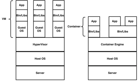
The main advantage of container virtualization over virtualization is that it shares a single host OS and single kernel but creates containers inside that OS which include all the software, environment and libraries for a particular application. Virtualization on the other hand requires the system to run multiple copies of the guest OS, which requires much memory and drastically degrades the performance of the whole system.
7https://www.chef.io/chef/ 8https://puppet.com/ 9https://jujucharms.com/
In container virtualization, the virtual OS does not need to duplicate the host system’s functionality, the host system is responsible for managing these system calls and the hardware. Which actually increases the performance of the system by hosting more virtual machines (VMs) [SPF+07], [Sch14].
The main challenge in container virtualization is the isolation problem. Regardless of the isolation between the containers, they still share the same host OS which makes it vulnerable for security threats to the entire system. Another drawback of container virtualization is that each container must use the same OS as the base OS, whereas virtualization instances can each run on a unique OS. For example, a container created on a Linux-based host could not run an instance of the Windows Server OS or applications designed to run on Windows Server.
Figure 2.1:VM vs Container Virtualization Design10
Container virtualization achieved importance with the open source project Docker [Tur14], which developed a method to give containers better portability and enable them to be moved among any system that shares the host OS type without requiring code changes. Details about Docker are being discussed in the following section 2.5. In addition to Docker, CoreOS [Cora] delivers a well-organized alternative to market, which is called Rocket [Corb]. In this thesis we consider Docker for our container virtualization
2.3 Topology and Orchestration Specification for Cloud Application
technology as it is now the most prominent and stable container virtualization technology available.
2.3 Topology and Orchestration Specification for Cloud
Application
The Topology and Orchestration Specification for Cloud Applications (TOSCA) is an XML based/YAML based language and a metamodel for describing service templates [TOSCA-Simple-Profile-YAML16]. TOSCA enhances the portability of multi-cloud appli-cations by enabling fully automated deployment, termination and further management functionalities.
The relationship between the service structure and management aspects as well as operational behavior of services are independent of the Cloud provider or a certain environment. In TOSCA, the structure of a service template is described by the topology template, which is a graph of node templates modeling the components. And relationship between those components are modeled by relationship templates. TOSCA also provides types for node template and relationship template. Here (i) node types are for node templates and (ii) relationship types are for relationship templates.
The following sub-section explaines the most important elements of the TOSCA specifi-cation [TOSCA-Simple-Profile-YAML16] using version 1.0.
2.3.1 TOSCA Syntax
Service Template
The service template element is the root element of a TOSCA YAML document. It has a set of properties, a Service Template is typically used to specify the “topology” (or structure) and “orchestration” (or invocation of management behavior) of IT services so that they can be provisioned and managed in accordance with constraints and policies [TOSCA-Simple-Profile-YAML16].
Specifically, TOSCA service templates optionally allow definitions of a TOSCA topology template, TOSCA types (e.g., Node, Relationship, Capability, Artifact, etc.), groupings, policies and constraints along with any input or output declarations [TOSCA-Simple-Profile-YAML16].
tosca_definitions_version: # Required TOSCA Definitions version string # Optional metadata keyname: value pairs
metadata:
template_name: # Optional name of this service template
template_author: # Optional author of this service template
template_version: # Optional version of this service template # Optional list of domain or profile specific metadata keynames # Optional description of the definitions inside the file. description: < template_type_description >
dsl_definitions:
# list of YAML alias anchors (or macros) repositories:
# list of external repository definitions which host TOSCA artifacts imports:
# ordered list of import definitions artifact_types:
# list of artifact type definitions data_types:
# list of datatype definitions capability_types:
# list of capability type definitions interface_types:
# list of interface type definitions relationship_types:
# list of relationship type definitions node_types:
# list of node type definitions group_types:
# list of group type definitions policy_types:
2.3 Topology and Orchestration Specification for Cloud Application
topology_template:
# topology template definition of the cloud application or service
Listing 2.1: Syntax of TOSCA Service Template [TOSCA-Simple-Profile-YAML16]
Topology Template
The following subsection describes the topology template which is the main element of service template, node template, and relation template. A topology template defines the structure of a service in the context of a service template. A topology template consists of a set of node template and relationship template definitions that together define the topology model of a service as a (not necessarily connected) directed graph [TOSCA-Simple-Profile-YAML16].
The main elements of the topology template are node templates which represent the components of the application and are assumed as the vertices of a graph, where rela-tionship templates represent links between the components and are assumed as edges. These relations define such as one component is"hosted on" or"communicates with"
the other component. These elements are defined in the nested node templates section and the nested relationship templates sections, respectively. Furthermore, a topology template allows for defining input parameters, output parameters as well as grouping of node templates. topology_template: description: <template_description> inputs: <input_parameter_list> outputs: <output_parameter_list> node_templates: <node_template_list> relationship_templates: <relationship_template_list> groups: <group_definition_list> policies: - <policy_definition_list>
# Optional declaration that exports the Topology Template # as an implementation of a Node Type.
substitution_mappings: node_type: <node_type_name> capabilities: <map_of_capability_mappings_to_expose> requirements: <map_of_requirement_mapping_to_expose>
Listing 2.2:Syntax of TOSCA Topology Template [TOSCA-Simple-Profile-YAML16]
Node Type
observable properties which are used to define a node template. Such are properties definition, requirements, capabilities, interfaces and artifacts. The following paragraph describes the above mentioned properties of a node type entity.
Properties define an optional list of property definitions for the node type. The property definition defines a named, typed value and related data which can be associated with node type. Properties are used by template authors to provide input values to node type to indicate their "desired state" when they are instantiated. The value of a property can be retrieved using the get_property function within TOSCA service templates [TOSCA-Simple-Profile-YAML16].
Requirements describe an optional list of sequenced requirements definition for the Node Type. According to TOSCA Simple Profile Specification [TOSCA-Simple-Profile-YAML16], The Requirement definition describes a named requirement of a TOSCA Node Type which needs to be fulfilled by a matching Capability definition declared by another TOSCA entity. The requirement definition can explicitly include the specific name of the fulfilling entity or provide an abstract type, along with additional filtering characteristics, that a TOSCA orchestrator can use to fulfill the capability at runtime.
Capability Definitions
Describes the optional list of capability definitions for the node type. A capability definition specifies a named, typed set of data that can be associated with node type to describe a capability or feature of the software component the node describes, regarding the TOSCA Simple Profile Specifications [TOSCA-Simple-Profile-YAML16].
Interfaces are reusable entities that define a set of operations that can be included as part of a node type as well as relationship type definition. Each named operations may have code or scripts associated with them that orchestrator can execute when transitioning an application to a given state [TOSCA-Simple-Profile-YAML16].
Relationship Type
Relationship types specify the type of one or more relationships between node types or node templates in a topology graph. Similar to the node types the relationship types offer some featured properties and potential states during runtime. According to TOSCA Simple Profile Specification [TOSCA-Simple-Profile-YAML16], the best practice is to use TOSCA root relationship type (tosca.relationships.Root) to derive new types where pos-sible, when defining new relationship types. It ensures that its normative configuration interface (tosca.interfaces.relationship.Configure) can be used in a deterministic way by TOSCA orchestrators.
Artifact Type
According to TOSCA Simple Profile Specification [TOSCA-Simple-Profile-YAML16], ar-tifact types represent the types of packages and files used by the orchestrator when
2.3 Topology and Orchestration Specification for Cloud Application
deploying TOSCA node or relationship types or invoking their interfaces. Currently, artifacts are logically divided into three categories [TOSCA-Simple-Profile-YAML16]:
• Deployment Types: includes those artifacts that are used during deployment (e.g., referenced on create and install operations) and include packaging files such as RPMs, ZIPs, or TAR files.
• Implementation Types: includes those artifacts that represent imperative logic and are used to implement TOSCA Interface operations. These typically include scripting languages such as Bash (.sh), Chef and Puppet.
• Runtime Types: includes those artifacts that are used during runtime by a service or component of the application. This could include a library or language runtime that is needed by an application such as a PHP or Java library.
2.3.2 TOSCA Example
In this example section, we will discuss about a TOSCA template for a simple software installation. This example is derived from TOSCA Simple Profile Specification [TOSCA-Simple-Profile-YAML16].
tosca_definitions_version: tosca_simple_yaml_1_0
description: Template for deploying a single server with MySQL software on top. topology_template: inputs: my_mysql_rootpw: type: string my_mysql_port: type: integer node_templates: mysql: type: tosca.nodes.DBMS.MySQL properties:
root_password: { get_input: my_mysql_rootpw } port: { get_input: my_mysql_port }
requirements:
- host: db_server db_server:
type: tosca.nodes.Compute capabilities:
# Host container properties host:
properties:
num_cpus: 1 mem_size: 2048 MB disk_size: 10 GB
# Guest Operating System properties os:
properties:
# host Operating System image properties architecture: x86_64
type: linux
distribution: ubuntu version: 14.01
Listing 2.3: Example-TOSCA Template for a Simple Software Installation [TOSCA-Simple-Profile-YAML16]
The example provided in the listing 2.3, is a basic TOSCA template for software installation. Installation of software can be defined in node templates with its re-lated server where the software will be installed. In this example the used node type is tosca.nodes.DBMSMYSQLfor mysql node template which will install MYSQL on a server. mysql node has multiple properties such as root_password and port.
root_passwordwill set the password of the MYSQL root user at the deployment time. These properties are set as an input parameter and used byget_input function, that means a value will be provided by the user at the deployment time and this value will be set to the corresponding property.
In thedb_servernode template, the ‘host’ capability contains some optional properties that allow application developers to set the number of CPUs, memory size and disk size they think will be needed when the Compute node is instantiated in order to run the respective applications. Similarly, the ‘os’ capability is used to provide values to indicate which type of operating system should be used, when the Compute node get initialized.
In the topology template, the mysql node template depends on the db_server node template, which has the type tosca.nodes.Compute. The relationship between these two node has been established using therequirementssection’s ‘host’ field in themysql
node template. This ‘host’ relationship indicates where the MYSQL application is to be installed. Nodes are related in the TOSCA metamodel based on requirements, where one node needs some features and another node is providing those features against the requirement, these type of requirements are defined by the node type. From the ongoing example, where MYSQL is a software type which needs to be hosted or installed on Compute type resource.
2.4 Kubernetes
Figure 2.2: Diagram-TOSCA Template for a Simple Software Installation [TOSCA-Simple-Profile-YAML16]
2.4 Kubernetes
Kubernetes [kubernetes] is an open source platform for automating container operations such as deployment, scheduling and scalability across a cluster of nodes. It has been developed by Google. And it is a similar approach to Borg and Omega [BGO+16], those projects were used within Google for long time and considered as a first unified container management system developed in Google but not considered as open source.
If user have ever used Docker container technology to deploy their containers, then think of Docker as a low level component used internally by Kubernetes to deploy containers. Kubernetes not only support Docker also supports Rocket, which is another container technology available in the market.
Kubernetes allows the user to declaratively specify the desired state of a cluster using high-level primitives. For example, the user may specify that they want three instances of the Wordpress application container running. Kubernetes’ self-healing mechanisms, such as auto-restarting, rescheduling and replicating containers then converge the actual state towards the desired state.
Kubernetes cluster can be started from different platforms, the most common ones used being Vagrant, Amazon Web Service (AWS), Google Compute Engine (GCE), and Azure etc. To run Kubernetes locally and easily Minikube is the most prominent solution nowadays. This thesis considers the Minikube tool to run Kubernetes for implementation and testing purposes as it is open source and it can be used locally. Details on Kubernetes management and design for different platforms are described in [Voh17].
Kubernetes orchestrates the containers in such a way that together they are performing as a Symphony. Some of them are followings [kubernetes]:
• automate the deployment and replication of containers, • scale in or out containers on the fly,
• organize containers in groups and provide load balancing between them, • easily roll out of new versions of application containers,
• provide container resilience, if a container dies it gets replaced, etc.
Key Concepts of Kubernetes Cluster
A cluster is a group of nodes. They can be physical servers or virtual machines that have the Kubernetes platform installed. The diagram below is an illustration of such cluster. This diagram is very simplified to highlight the key concepts [DO15].
According to the 2.3 diagram, the following Kubernetes components are: • Pod
• Container • Label
2.4 Kubernetes
Kubernetes Master
API Server
Replication Controller
kubelet kube-proxy docker
Node Pod
Container
Pod
Container
kubelet kube-proxy docker
Node Pod Container Pod Container Kubernetes Cluster my-service1 my-service2 = Labels = Service Scheduler
Figure 2.3:Simple Kubernetes Architecture Diagram [DO15] • Service
• Node
• Kubernetes Master
Pod
Pods are the smallest deployable units in Kubernetes that can be created, scheduled and managed. It is all about the Pods, if a user deploys a single container it will be deployed in its own Pod. Hence, it is a logical collection of containers that belong to an application.
Pods are scheduled to Nodes and contain a group of co-located Containers and Volumes. Containers in the same Pod share the same network namespace and can communicate with each other using localhost. Pods are considered to be ephemeral rather than durable entities.
apiVersion: v1 kind: Pod
# labels attached to this Pod metadata: labels: name: wordpress-pod spec: containers: - name: wordpress
# Docker image that will run in this Pod image: wordpress
ports:
- containerPort: 8080
Listing 2.4:Example of Pod
Label
A Label is a key/value pair attached to Pods and conveys user-defined attributes. Labels define identifying for the object and are only meaningful and relevant to the user. Multiple labels can be attached to a resource. Labels can be used to organize and to select subsets of objects.
For example, users might create a ‘tier’ and an ‘app’ tag to tag their containers by applying the Labels (tier=frontend, app=myapp) to the frontend Pods and Labels (tier=backend, app=myapp) to backend Pods. Users can then use Selectors to select Pods with particular Labels and apply Services or Replication Controllers to them [Gup16].
Replication Controller
Replication Controllers ensure the specified number of Pod ‘replicas’ that are running at any moment. If users created a Replication Controller for a Pod and specified 3 replicas, this will create 3 Pods and will continuously monitor them. If one Pod dies then the Replication Controller will replace it to maintain a total count of 3.
If the Pod that died comes back then users have 4 Pods, so consequently the Replication Controller will terminate one and the total count is 3. Again if users change the number of replicas to 5 on the fly, the Replication Controller will immediately start 2 new Pods so the total count is 5. User can also scale down Pods this way, a handy feature performing rolling updates.
When creating a Replication Controller users need to specify two things:
• Pod Template: the template that will be used to create the Pods replicas. • Labels: the labels for the Pods that this Replication Controller should monitor.
2.4 Kubernetes
Following is the example of a replication controller.
apiVersion: v1
kind: ReplicationController metadata:
name: wordpress-controller spec:
# Two replicas of the Pod to be created replicas: 2
# Identifies the label key and value on the Pod that # this Replication Controller is responsible for managing selector:
app: wordpress-rc-pod
# "cookie cutter" used for creating new pods when necessary template:
metadata: labels:
# label key and value on the pod.
# These must match the selector above. app: wordpress-rc-pod spec: containers: - name: wordpress image: wordpress ports: - containerPort: 8080
Listing 2.5: Example of Replication Controller
Service
Service is an abstraction that defines a set of Pods and a policy to access them. Services find their group of Pods using Labels. The IP address assigned to a Service does not change over time and thus can be relied upon by other Pods. Usually, the Pods belonging to a Service are defined by a label selector. The labels used in selector must match the metadata used for creating the Pod by the Replication Controller.
apiVersion: v1 kind: Service metadata: name: wordpress-service labels: app: wordpress-service spec: ports: - port: 8080
# label keys and values of the Pod started elsewhere selector:
app: wordpress-container
Listing 2.6: Example of Service
Node
A node is a physical or virtual machine that acts as a Kubernetes worker, used to be called Minion. Every node has the following components such as kubelet, kube-proxy and Docker [DO15].
Kubelet
Kubelet runs on every node act as a primary node agent, which manages the containers. And it is managed by the master. It works on the base of Pod specification accepting JSON or YAML which describes the Pod, also ensures that the containers inside the Pods are started and running.
Kubernetes Master
Kubernetes master is the central control point which manages the other worker nodes. It provides unified view into the cluster and has a number of components. It includes replication controller which is responsible for creation and replication of pods.
Deployment
Deployment is the next generation replication controller, recently introduced by Ku-bernetes. It provides declarative updates for Pods and Replica Sets. User only need to describe the desired state in a Deployment object, and the Deployment controller will change the actual state to the desired state at a controlled rate. Users can define Deployments to create new resources or replace existing ones by new ones. According to Kubernetes guideline use cases of deployment are the following [kubernetes]:
• Perform a Deployment to set up a Replica Set and Pods, • Monitoring the status of a deployment,
• Update the existing deployment to recreate the Pods,
• If current deployment is not stable it is possible to rollback to previous stable version,
2.4 Kubernetes
Either Replication Controller or Deployment can be used to create and replicate Pods. But Deployment provides some advanced features over Replication Controller like, it allows for easy updating of a Replica Set as well as the ability to roll back to a previous deployment.
Following is the example of a deployment artifact:
apiVersion: v1 kind: Deployment metadata: name: wordpress-container labels: app: wordpress-container spec: replicas: 2 template: metadata: labels: app: wordpress-container spec: containers: - name: wordpress image: wordpress:4.6.1-apache env: - name: WORDPRESS_DB_HOST value: mysql-container - name: WORDPRESS_DB_PASSWORD value: root ports: - containerPort: 80
Listing 2.7:Example of Deployment
Topological example of Kubernetes
After deploying the 2.7 deployment file and 2.6 file in Kubernetes the topological view inside the cluster might look like the following diagram:
Figure 2.4:Example of Kubernetes Application Topology Based on [Gup16]
In the figure 2.4 here two "wordpress" pods have been created and both of them are discovered by the corresponding "wordpress" service.
Example of Multi-Container Pods in Kubernetes
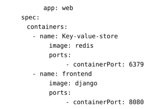
The example 2.4 shows a single Pod with a single container, while a single Pod can have multiple containers as well. According to the definition of Pod, “A pod is a group of containers that are scheduled onto the same host. Pods serve as units of scheduling, deployment, and horizontal scaling/replication” [kubernetes]. Hence, it is defined from the definition of Pod that we can have multiple containers inside a single Pod. In this following example 2.8 we will show how to create a single Pod with multiple containers.
The following example 2.8 has been used from Kubernetes website [kubernetes]:
apiVersion: v1 kind: Pod metadata:
name: redis-django labels:
2.5 Docker app: web spec: containers: - name: Key-value-store image: redis ports: - containerPort: 6379 - name: frontend image: django ports: - containerPort: 8080
Listing 2.8: Example of Multi-Container Pod Based on [kubernetes]
In the example 2.8 each container definition has been defined in the"containers array". Each container object must contain"name"of the container and"image"Docker image name.
Following diagram 2.5 is the pictorial representation of the example 2.8.
Figure 2.5: Graphical Representation of Multi-Container Pod
2.5 Docker
According to Docker website, it is described as “an open-source engine that automates the deployment of any application as a lightweight, portable, self-sufficient container that will run virtually anywhere.” [Docker]
Docker makes it easier for organizations to automate infrastructure, isolate applications, maintain consistency and improve resource utilization.
There are many key components of Docker which are used to manage Docker. These are: • Docker Images • Docker Containers • Docker Client • Docker Host • Docker Registry • Docker Machine
Key Concepts of Docker Docker Image
A template for creating containers. An image contains the installation steps of an application instance with its software and independence, and the process to run when the container is launched. Docker images can be build from a Dockerfile. Pre-built Docker images can be found in the Docker registry.
Dockerfile
The core component of a Docker project is the Dockerfile. This file contains the instruc-tions for Docker on how to build the Docker Image. Using "docker build" command users can easily build a Docker image from a Dockerfile.
Docker Container
Docker Container is a runtime component of Docker which is a virtual machine. It is created from the instruction found in the Docker image. A container holds everything that is needed for an application instance to run, including an operating system, user-added files, meta-data, and application instance dependencies.
Docker Registry
Docker Registry is a repository of images, where users can upload their created images or can download a pre-built image. Docker registry can be public or private. The most popular public Docker registry is Docker Hub11.
2.6 Related Works
2.6 Related Works
In the following section, similar works related to the fundamental concepts involved in this thesis are presented. These similar projects are related to the area of virtualization deployment, specially those related to container deployment and cluster deployment of containers, Also Cloud orchestrators which use the TOSCA standard specification to deploy and manage applications in Cloud.
2.6.1 OpenTOSCA
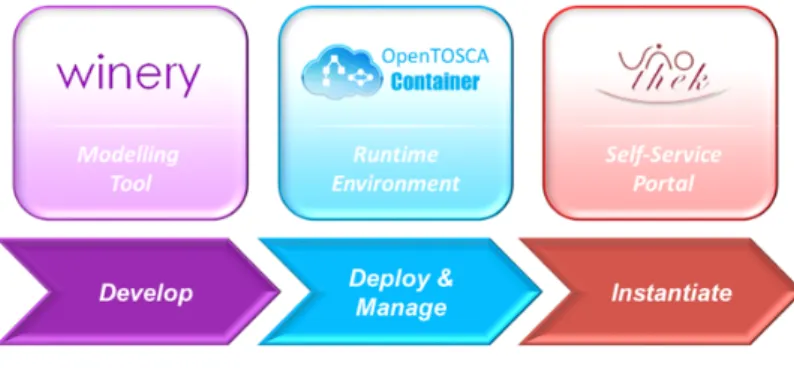
OpenTOSCA [BBKL14a] is an open-source runtime environment for TOSCA environment, which was developed by “Institute of Architecture of Application Systems” (IAAS) at the University of Stuttgart. The OpenTOSCA-ecosystem is split into three parts: (i) OpenTOSCA-Container, (ii) Winery and (iii) Vinothek.
Figure 2.6:OpenTOSCA Ecosystem Overview12
OpenTOSCA-Container
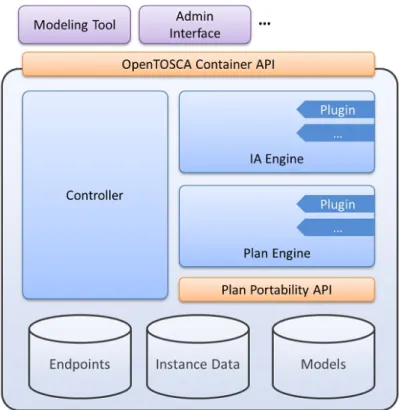
OpenTOSCA-Container [BBH+13] is a runtime environment for the TOSCA descrip-tion which is responsible for deployment and management. It processes the Cloud Service Archives (CSARs), runs plans and also manages the deployment states. Inside this OpenTOSCA-Container it is possible to deploy and manage TOSCA generated ap-plications. From the definition of OpenTOSCA-Container [BBH+13], it is defined as TOSCA runtime environment, therefore, this is not a container in the sense of container virtualization. More details about OpenTOSCA runtime architecture and components are provided in [BBH+13].
12http://www.iaas.uni-stuttgart.de/OpenTOSCA/OpenTOSCAEcosystem.png 13http://www.iaas.uni-stuttgart.de/OpenTOSCA/container_architecture.php
Figure 2.7:OpenTOSCA Container Architecture13
Winery
Winery [KBBL13] is a graphical modeling TOSCA tool to create TOSCA CSARs. Currently it supports visual modeling of topologies, defining TOSCA-Types and Templates and management plans. Which can be later exported as a CSAR to a TOSCA runtime. Winery enables users to build new web or Cloud applications by using the existing node types and relationship types. The CSAR files generated from Winery consists of XML-based definition file. On the other hand, this thesis is focused on YAML based TOSCA definition file. Therefore, it is difficult to reuse the features of Winery in this thesis.
Vinothek
Vinothek [BBKL14b] is a Web-based self-service portal for “OpenTOSCA”. It hides the technical details of TOSCA runtimes and provides end users a graphical interface to provisioning Cloud services over “OpenTOSCA”. Provisioning term means the process to get the needed Cloud resources such as CPU, memory and storage etc. More details about Vinothek User Interaction and system overview are provided in [BBKL14b].
2.6 Related Works
Figure 2.8:Cloudify Architecture Overview14
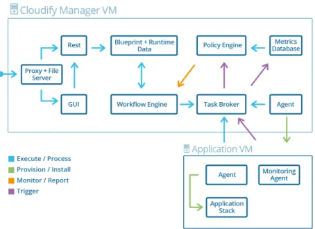
2.6.2 Cloudify
Cloudify [Gig] is an open source Cloud orchestration tool developed by GigaSpaces Technologies. Cloudify is designed in such a way so that it can support any application regardless of the application stack (i.e. languages and dependencies), can be deployed on any IaaS Cloud, and provides full control over the underlying infrastructure to its users, such as monitoring all aspects of the deployed application, detecting issues and failure, manually or automatically repairing them and handle ongoing maintenance tasks.
Cloudify’s DSL (Domain Specific Language) is based on TOSCA’s YAML Simple Profile [TOSCA-Simple-Profile-YAML16], which are called “blueprint” defines the application’s configurations, services and their topology. Using these blueprints Cloudify orchestrate the deployment phases of applications to Cloud computing and Virtualization infras-tructure. In this blueprint files user can define the execution plans for the lifecycle of the application for installing, starting, terminating, orchestrating and monitoring the application. One of major part of Cloudify is the Cloudify DSL parser, which intends to read and validate the TOSCA blueprints and using its own workflow engine provide a mechanism for mapping operations to Cloudify plugins. More details about Cloudify DSL is provided in [Gig].
Cloudify is already integrated with Microsoft Windows Azure, Amazon EC2, Docker and Kubernetes. Also supports configuration management tools like Chef, Puppet, Ansible. Despite the fact that, Cloudify completely comply with our thesis goal, but we think that in some part it does not support the whole TOSCA features such as Cloudify does not support CSARs and also it has own specific DSL version that looks for namespacing specific to Cloudify. Therefore, Cloudify does not compliance with the TOSCA standard completely and creates vendor lock-in for its users.
2.6.3 OpenStack Heat
OpenStack Heat [Opea] is an open-source project which initially launched as an alterna-tive to AWS CloudFormation which is a closed source project. This is one of the largest projects to adopt TOSCA as one of the main templating languages.
Heat is the main orchestration component of the OpenStack [Opec] orchestration program. It allows users to describe deployments of composite Cloud applications in text files called Heat templates. These templates define infrastructure resource requirements, the relationship between these resources, and any software configuration necessary in order to manage a complete application lifecycle. Later on these templates are then parsed and executed by the Heat engine. Heat also accepts the AWS CloudFormation template format, so that many existing CloudFormation templates can be launched on OpenStack. Heat provides both an OpenStack-native ReST15 API and a
CloudFormation-compatible Query API.
As OpenStack Foundation is moving towards TOSCA standardization for the entire project, therefore they established TOSCA as their primary templating language. From the recent Heat Translator project [Opeb], It takes a TOSCA flat YAML template or template embedded in TOSCA Cloud Service Archive (CSAR) format as an input, calls an appropriate Parser (e.g. TOSCA Parser) per the type of input template to parse it and create an in-memory graph, maps it to Heat resources and then produces a Heat Orchestration Template (HOT) as an output.
2.6 Related Works
Figure 2.9:Simplified Architecture Diagram of Heat-Translator16
In recent time Heat is integrated with Kubernetes and Cloudify beside AWS platform. Which makes it more powerful and increases its usability as a strong Cloud Orchenstra-tion tool.
This project could be the best fit for our thesis, despite of its strong functionality and usability this project is mostly infrastructure focused. Even though Heat project takes TOSCA YAML as an input but later on it translates TOSCA to its own defined Heat Orchestration Template (HOT). After that HOT templates are used for Orchestration purpose. Which makes this project mostly OpenStack centric. Therefore, it mostly compatible with Other OpenStack components.
16
3 Requirements
In this part, the abstract mapping goal and the requirements of system architecture will be discussed. Technologies and different components which have emerged in the building process of the system architecture will be explored in this requirements section.
3.1 Mapping Goal
As described in the introduction chapter the goal of this thesis is to deploy TOSCA Cloud service archives using Kubernetes. From the fundamental chapters, it is found that TOSCA archives has its own definition files along with different artifact files, while on the other hand Kubernetes requires different deployment artifact files to deploy applications in it. Hence, it is obvious that different TOSCA files need to be mapped with diverse Kubernetes requirement and have to generate Kubernetes deployable files. The overall mapping goal is to map each TOSCA specific requirement to the Kubernetes specific requirement and include all necessary components to generate Kubernetes artifacts. A more detailed description is given in Chapter 4.
3.2 Architecture Requirements
To map between TOSCA and Kubernetes it is required to build a transformation engine which will transform TOSCA specific artifact and maps it to Kubernetes specific artifact. The building process of the transformation engine requires a system architecture which is composed of some key technologies.
System requirements have been distinguished between technical and non-technical requirements based on the system architecture. In the following subsections both of these requirements are described.
Following figure 3.1 is the basic system architecture with the key components and required technologies:
Figure 3.1:Conceptual Architecture Diagram
3.2.1 Technical Requirements
Main key technologies shown in the figure 3.1 of system architecture to construct the transformation engine are:
• TOSCA archives: TOSCA archives are the TOSCA specification files which define the nodes, metadata, node topology and relationship between the nodes. Also it provides supporting documents as a script to maintain the applications.
• TOSCA parser: A parser is required to parse the TOSCA archives and get the required information from the definition files. This parser will be based on python runtime. It takes TOSCA archive (CSAR) files as an input. Also the definition files provided in the CSAR file must be of ".yaml" extension. To parse the ".yaml" file this parser uses the python yaml parser library as a base parser to read the file and extract the parsed data.
• Mapper: To map TOSCA to Kubernetes and the intermediate Dockerfile a mapper will be needed. This mapper will get the required data from the TOSCA parser and map the diverse system requirements between TOSCA and Kubernetes. This mapper will be based on python.
• Kubernetes file generator: File generator for generating the Kubernetes specific deployment file. This file generator generates two different types of file (i) Deploy-ment and (ii) Service file for Kubernetes deployDeploy-ment. The file extension is ".yaml" type.
• Dockerfile generator: This file generator will generate the Docker specific file. The extension of the file will be Dockerfile. Also this file generator copies the
3.2 Architecture Requirements
required scripts/files to the same directory of the Dockerfile in order to copy this file inside the Docker container and execute them inside the Docker container. • Docker Engine: Docker Engine is required to be configured in the host machine
to build and push Dockerfiles to the Docker hub. It is required to build and run containers.
• Kubernetes Engine: Pre-Installed Kubernetes is required in the host machine to be able to deploy Kubernetes specific file and generate Pods and associated service for the Pods. "Minikube" can be used to run Kubernetes locally. According to [Minikube] , "Minikube" is a tool that makes it easy to run Kubernetes locally. Minikube runs a single-node Kubernetes cluster inside a VM on user’s laptop for users looking to try out Kubernetes or develop with it day-to-day."
3.2.2 Non-Technical Requirements
Apart from the technical requirement there are also some non-technical requirements in the system. This non-technical components are involved in all of the system to maintain the end-to-end process of the transformation engine. Such non-technical components are:
• TOSCA CSAR:TOSCA Cloud service archive (CSAR) is a zip file, which contains all the required artifacts of TOSCA such as scripts, binaries, configuration files along with the metadata file and definition files. These files are required to deploy TOSCA using a TOSCA orchestrator.
• TOSCA artifacts: TOSCA artifacts consist of different scripts and configuration files, which are needed to create, install, implement and configure TOSCA applica-tion properly while deploying it into the Cloud.
• Dockerfiles: Dockerfiles are an intermediate requirement in the whole mapping process between TOSCA and Kubernetes. As Kubernetes only supports pre-built Docker image for its container deployment process, it is needed to map between TOSCA to Dockerfiles and then build Docker images from these files. Another way is to provide Docker image name of the specific application in the TOSCA definition file which can be directly mapped to Kubernetes.
• Kubernetes Deployment files: Deploying applications into Kubernetes requires two essential files which are the deployment file and service file. Deployment file is a manifest file which describes the Pods and Containers, as well as the Ports and the Replication process. The service file is to discover the proper Pod which is
currently running. Details about deployment and service artifacts are provided in Chapter 2
3.3 Supported Operations
The Transformation engine needs to support some specific operations in order to success-fully map TOSCA to Docker and Kubernetes. According to the Simple Profile specification of TOSCA [TOSCA-Simple-Profile-YAML16] these operations are described as Standard Lifecycle Interface ("tosca.interfaces.node.lifecycle.Standard"). This interface can be included into a node type definition as a set of operations. Each operation can have scripts attached with it, which can be executed by the orchestrators while transitioning an application to a desired state. The essential lifecycle operations which are supported by TOSCA nodes are the following:
• create: A standard lifecycle operation. It is used to create the resource or service the node represents in its definition. The orchestrators expect the node to provide a deployment artifact or an implementation artifact of a defined artifact type that it is able to process.
• configure: This operation is used to configure the resource the node represents in the topology.
• start: Start operation has the same kind of features as described in the create and configure operation.
These standard operations are supported in the transformation engine to generate node specific resources and configure them. Each of these operations and their corresponding artifacts have been mapped to Docker file to execute them in a required manner.
3.4 Supported Artifacts
From the fundamental chapter 2.3.1 and according to TOSCA simple profile specification [TOSCA-Simple-Profile-YAML16], an artifact definition defines a named, typed file that can be associated with Node Type or Node Template and is used by orchestration engine to facilitate deployment and implementation of interface operations. Therefore, artifacts might be of different types such as deployment artifacts and implementation artifacts, which can be used by the orchestrator for the deployment and implementation purpose. These artifact files can have different variations such as ZIP files, TAR files or scripting languages such as Bash (.sh) scripts. Hence, to run the operations in the lifecycle
3.4 Supported Artifacts
interface defined in TOSCA node templates, it is required to provide these artifacts (scripts or code) to the orchestrator which then will be executed to get the desired service or resource.
The artifacts supported by the Transformation engine are currently Bash (.sh) scripts and Docker image. If Docker image link is provided in the TOSCA node template for a node type then this image will be directly mapped to Kubernetes deploy-ment file as a container image. This Docker image is a deploydeploy-ment artifact type (tosca.artifacts.Deployment.Image.Container.Docker).
Following 3.1 is an example of a Dockerfile snippet which can be used as an artifact in the TOSCA node template:
FROM ubuntu:14.04
RUN apt-get update && apt-get install -y redis-server
EXPOSE 6379
ENTRYPOINT ["/usr/bin/redis-server"]
Listing 3.1:Sample Dockerfile Snippet of a Redis Server [Docker] This 3.1 Dockerfile can be used to build an image of redis-server.
On the other hand, instead of providing a Docker image, simple Bash (.sh) scripts can be provided as an artifact for deployment and implementation purpose. These scripts can also have some input values which can be provided in the node template along with the artifact definition. These scripts will be directly mapped to Dockerfile and will be executed inside the Dockerfile. Also the required inputs and environmental variables will be mapped and passed to the Dockerfile accordingly.
Following 3.2 is an example of a Bash (.sh) script file which can be used as an artifact in the TOSCA node template:
#!/bin/bash
#This script installs mysql server apt-get update
debconf-set-selections <<< "mysql-server mysql-server/root_password password $db_root_password"
debconf-set-selections <<< "mysql-server mysql-server/root_password_again password $db_root_password"
apt-get -y install --fix-missing mysql-server
4 Architecture and Design
In this chapter the mapping techniques from TOSCA definition to Kubernetes are to be described. Furthermore, the assumptions taken for this mapping will be discussed in the following section 4.2.
4.1 Concept of Mapping Techniques
Graphical Overview of Mapping Concept
Following is the pictorial representation of TOSCA to Kubernetes mapping concept.
Figure 4.1:TOSCA to Kubernetes Mapping Concept Diagram In the mentioned concept diagram the major components are following :
• TOSCA Template Parser : It will parse the TOSCA csar file and provides the required topology template, nodes and relationships with their properties.
• Docker Mapper : It will map the consolidated"HostedOn"relationship nodes to a Dockerfile and generate multiple Dockerfiles based on the requirements. Later it will build Docker image from Dockerfiles and push these images to Docker repository.
• Kubernetes Mapper : Kubernetes mapper will map the Docker images based on the "ConnectedTo" node relationship. It will generate the required deployment artifact to deploy the node in Kubernetes engine.
Before explaining the mapping concept on a more granular level, the assumptions made will be discussed in the following section 4.2. Therefore, it will be more clearer that how the mapping techniques works and what assumptions taken into account while mapping.
4.2 Assumptions
TOSCA itself is a quite enormous specification, having a large number of node types and relationship types, which also support vast amount of operations and properties. As the Transformation engine is a proto-type system, there are some limitations and specification assumptions have been made for the implementation purpose. Also, these assumptions have been taken because of mapping the diverse TOSCA specification to Kubernetes specific deployment. These assumptions illustrate the scope of this thesis and also depict its limitations.
Assumption 1: TOSCA archive (csar) files provided as a zip format
This thesis only considers the TOSCA archive (csar) files as a zip format with all the required artifacts. This csar file contains sub directories such as "TOSCA-Metadata",
"Definitions"and"Scripts". "TOSCA-Metadata" sub directory contain entry definition path of TOSCA template along with other meta-data. "Definitions"sub directory contain the definition files of TOSCA topology template and node template. "Scripts"contain the provided artifact scripts which are needed for deployment and implementation purpose of the node type.
Assumption 2: Supported node types
The transformation engine will support two types of nodes. If the Docker image name is provided in the node template it has to be"tosca.nodes.Container.Application.Docker"
node type. Otherwise, the node type has to be TOSCA application node type, which will be used as a Docker image name afterwards.
4.2 Assumptions
Inputs in the TOSCA topology template will be treated as environment variables, when mapping these inputs to Kubernetes deployment artifacts and Dockerfiles. Hence, it is considered in this thesis that all provided input name must be exactly same as the environment variable name in the application. The Transformation engine will prompt for user input if it detects inputs in TOSCA topology template.
Assumption 4: Supported functions to set properties and input values
In this Transformation engine only "get_input" and"get_property"built-in functions from TOSCA definition file have been considered to resolve when setting up the node inputs and node properties. These functions are built-in property functions in TOSCA, which are used within a service template to get the property values from property definitions which are defined somewhere else in the service template. Furthermore, these functions may only resolve the static values of property definitions of a TOSCA application. The Transformation engine will execute these property functions when there is a depedency between node which are related to specific node property. Furthermore, when there is a need to set user input value to particular node property that time
"get_input"function will be executed.
Assumption 5: Considered relationship between nodes
It is needed to link between two deployed applications in Kubernetes if there is a de-pendency between them. To map this requirement from TOSCA to Kubernetes, in this thesis "host","database_endpoint","service_endpoint","database_link"keywords in the node’s requirement section have been considered as a relationship type between nodes. Hence, it is expected to use the exact same keywords in the TOSCA definition files. The "host" keyword mimics the "HostedOn" relationship between two nodes which is required for Dockerfile mapping. This resolves the application hosting depen-dency. On the other hand"database_endpoint","service_endpoint","database_link"
keywords mimic the"ConnectedTo"relationship between the nodes, which is required in Kubernetes for linking between applications.
Assumption 6: Mapping of connection between nodes
In Kubernetes two deployed applications can be connected via environment variables and dns lookup. Therefore, it is required to map the proper Environment variable from TOSCA to Kubernetes for connecting two applications. As mentioned in Assumption 5, the connection between two nodes will be defined by "database_endpoint", "ser-vice_endpoint", "data_baselink" keywords and the target node name as its value in the requirement section. To get the "Environment variable" for connection purpose, it is assumed in this thesis, that in the TOSCA node templates of the target node inside the artifact section there will be a"kubernetes_metadata" part which will contain the "Environment variable" name as a value of key value-pair of "link_address".
Connection between two nodes as an example:
requirements:
- database_link: mysql_container
Listing 4.1:ConnectedTo Relationship Syntax "kubernetes_metadata" setup in the target node as an example:
mysql_container: artifacts:
kubernetes_metadata:
link_address: WORDPRESS_DB_HOST
Listing 4.2:"kubernetes_metadata" Setup Syntax
Later on this "ConnectedTo"relation will be mapped as a link between two applications in Kubernetes along with the key value pair.
The mapping concept has been described with TOSCA definition files on the following section 4.3. Here a single instance wordpress deployment scenario has been used to represent the mapping concept in different stages.
4.3 Mapping Concept using TOSCA Definition Files
Following is the TOSCA definition file of the wordpress example.tosca_definitions_version: tosca_simple_yaml_1_0 description: >
TOSCA simple profile with wordpress, web server and mysql on the same server. imports: - wordpress.yaml topology_template: inputs: db_name: type: string
description: The name of the database. db_user:
type: string
description: The user name of the DB user. db_pwd:
4.3 Mapping Concept using TOSCA Definition Files
type: string
description: The WordPress database admin account password. db_root_pwd:
type: string
description: Root password for MySQL. db_port:
type: integer
description: The host port that maps to port 3306 of the MySQL database. wp_host_port:
type: integer
description: The host port that maps to port 80 of the WordPress. node_templates:
wordpress:
type: tosca.nodes.WebApplication.WordPress properties:
service_type: LoadBalancer
port: { get_input: wp_host_port } requirements: - host: webserver - database_endpoint: mysql_database interfaces: Standard: create: ../Scripts/WordPress/install.sh configure: implementation: ../Scripts/WordPress/configure.sh inputs:
wp_db_name: { get_property: [ mysql_database, name ] } wp_db_user: { get_property: [ mysql_database, user ] }
wp_db_password: { get_property: [ mysql_database, password ] } mysql_database:
type: tosca.nodes.Database properties:
name: { get_input: db_name } user: { get_input: db_user } password: { get_input: db_pwd } port: { get_input: db_port } requirements: - host: mysql_dbms artifacts: kubernetes_metadata: link_address: wp_db_host interfaces: Standard: configure: implementation: ../Scripts/MYSQLDatabase/configure.sh inputs:
db_user: { get_property: [ mysql_database, user ] }
db_password: { get_property: [ mysql_database, password ] } db_root_password: { get_property: [ mysql_dbms, root_password ] } mysql_dbms:
type: tosca.nodes.DBMS properties:
root_password: { get_input: db_root_pwd } port: { get_input: db_port }
requirements: - host: server interfaces: Standard: create: ../Scripts/MYSQLDBMS/install.sh start: ../Scripts/MYSQLDBMS/start.sh configure: implementation: ../Scripts/MYSQLDBMS/configure.sh inputs:
db_root_password: { get_property: [ mysql_dbms, root_password ] } webserver: type: tosca.nodes.WebServer requirements: - host: server interfaces: Standard: create: ../Scripts/WebServer/install.sh start: ../Scripts/WebServer/start.sh server: type: tosca.nodes.Compute capabilities: host: properties: disk_size: 10 GB num_cpus: 1 mem_size: 4096 MB os: properties: architecture: x86_64 type: Linux distribution: Ubuntu version: 16.0 outputs: website_url:
description: IP address for Wordpress wiki.
![Figure 2.2: Diagram-TOSCA Template for a Simple Software Installation [TOSCA- [TOSCA-Simple-Profile-YAML16]](https://thumb-us.123doks.com/thumbv2/123dok_us/11057967.2992647/25.892.154.699.152.787/figure-diagram-template-simple-software-installation-simple-profile.webp)
![Figure 2.3: Simple Kubernetes Architecture Diagram [DO15]](https://thumb-us.123doks.com/thumbv2/123dok_us/11057967.2992647/27.892.156.689.167.559/figure-simple-kubernetes-architecture-diagram-do.webp)
![Figure 2.4: Example of Kubernetes Application Topology Based on [Gup16]](https://thumb-us.123doks.com/thumbv2/123dok_us/11057967.2992647/32.892.193.756.152.560/figure-example-kubernetes-application-topology-based-gup.webp)