UC Santa Barbara Electronic Theses and Dissertations
TitleInteractive Remote Collaboration Using Augmented Reality
Permalink https://escholarship.org/uc/item/03x0f03s Author Gauglitz, Steffen Publication Date 2014 Peer reviewed|Thesis/dissertation
Interactive Remote Collaboration
Using Augmented Reality
A dissertation submitted in partial satisfaction
of the requirements for the degree of
Doctor of Philosophy
in
Computer Science
by
Steffen Gauglitz
Committee in charge:Professor Tobias H¨ollerer, Co-Chair Professor Matthew Turk, Co-Chair Professor Pradeep Sen
Professor Susan Fussell, Cornell University Gerhard Reitmayr, Ph.D., Qualcomm Research
Pradeep Sen
Susan Fussell
Gerhard Reitmayr
Tobias H¨ollerer, Committee Co-Chair
Matthew Turk, Committee Co-Chair
Copyright c2014 by
I thank my advisors Tobias H¨ollerer and Matthew Turk for advising, supervising, guiding and
supporting me throughout graduate school. You have taught me about the art and science of
human-computer interaction and computer vision, about research, academia, writing grants and
papers. I feel that it has always been a comfortable environment and respectful relationship,
which I believe cannot be overrated.
I thank Sue Fussell, Gerhard Reitmayr, and Pradeep Sen for serving on my dissertation
committee: You have provided expertise and feedback from other angles; and I believe that
this has made this work stronger and more well-rounded.
I thank Qualcomm, and in particular Serafin Diaz, Daniel Wagner and Alessandro Mulloni,
for making an important piece of software available to us for this work, and for supporting us
to put it to use most effectively. This has allowed us to build upon a very reliable solution and
concentrate on other research aspects; I hope that the collaboration was to mutual benefit.
I thank my collaborators and co-authors Lukas Gruber, Stefanie Zollmann, Victor Fragoso,
Luca Foschini, Cha Lee, Jon Ventura, Chris Sweeney, and in particular Ben Nuernberger; you
have helped me to implement and realize ideas and write great papers about them. I hope that
the collaborations and friendships may endure. I also thank all other members, and visitors, of
the Four Eyes Lab (and my advisors for attracting them); all of you let me bounce ideas off,
provided expertise and advised me professionally and/or scientifically in different ways.
Last, but certainly not least, I thank my parents for supporting me to go on an adventure
9000 kilometers away, and my wonderful wife, Julia, for supporting me throughout this
jour-ney, proofreading, bringing food to lab, lending her voice to our videos, celebrating successes
and enduring stressful times, and spending lots of time with our daughter on top of pursuing
Steffen Gauglitz
September 2014
Education
2014 Doctor of Philosophy, Computer Science, UC Santa Barbara
2008 Diplom-Ingenieur, Computer Engineering, RWTH Aachen University
Work Experience
2012 Intern, Google, Inc.
2010 Intern, Qualcomm, Inc. Corporate Research & Development 2008 – 2014 Graduate student research assistant,
Department of Computer Science, UC Santa Barbara 2007 – 2008 Intern, WorldViz, LLC
2005 – 2006 Student research assistant,
Institute of Man-Machine Interaction, RWTH Aachen University (part time) 2003 – 2005 Programmer, linear GmbH (part time)
Awards & Fellowships
2014 Outstanding Dissertation Honorable Mention, Department of Computer Sci-ence, UC Santa Barbara
2013 Second-best Paper Award, UC Santa Barbara Computer Science Graduate Stu-dent Workshop on Computing
2012 Best Paper Award, IEEE International Symposium on Mixed and Augmented Reality (ISMAR)
2012 Best Paper Honorable Mention, ACM SIGCHI’s International Conference on Human-Computer Interaction with Mobile Devices and Services (MobileHCI) 2012 Outstanding Graduate Student Award, Department of Computer Science, UC
Santa Barbara
2010 Outstanding Teaching Assistant Award, Department of Computer Science, UC Santa Barbara
2010 Springorum Coin, RWTH Aachen University, “in recognition of outstanding academic achievement”
2003 – 2008 Fellow of the Studienstiftung des deutschen Volkes (German National Aca-demic Foundation)
Publications
In Journals:
S. Gauglitz, C. Sweeney, J. Ventura, M. Turk, and T. H¨ollerer: Model estimation and selection towards unconstrained real-time tracking and mapping. InIEEE Transactions on Visualization and Computer Graphics (TVCG), vol.20, no.6, pp.825-838, 2014
S. Gauglitz, T. H¨ollerer, and M. Turk: Evaluation of interest point detectors and feature descriptors for visual tracking. In International Journal of Computer Vision (IJCV), vol.94, no.3, pp.335-360, 2011
In Conference Proceedings:
S. Gauglitz, B. Nuernberger, M. Turk, and T. H¨ollerer: In Touch with the Remote World: Remote Collaboration with Augmented Reality Drawings and Virtual Navigation. In Proceedings of the ACM Symposium on Virtual Reality Soft-ware and Technology (VRST) 2014, Edinburgh, UK,to appear
S. Gauglitz, B. Nuernberger, M. Turk, and T. H¨ollerer: World-stabilized Annotations and Virtual Scene Navigation for Remote Collaboration. InProceedings of the ACM Symposium on User Interface Software and Technology (UIST) 2014, Honolulu, USA,to appear
S. Gauglitz, C. Sweeney, J. Ventura, M. Turk, and T. H¨ollerer: Live tracking and mapping from both general and rotation-only camera motion. InProceedings of the IEEE International Symposium on Mixed and Augmented Reality (IS-MAR) 2012, Atlanta, USA
S. Gauglitz, C. Lee, M. Turk, and T. H¨ollerer: Integrating the physical environment into mobile remote collaboration. In Proceedings of the ACM SIGCHI In-ternational Conference on Human-Computer Interaction with Mobile Devices and Services (MobileHCI) 2012, San Francisco, USA
S. Gauglitz, M. Turk, and T. H¨ollerer: Improving keypoint orientation assignment. InProceedings of the British Machine Vision Conference (BMVC) 2011, Dun-dee, UK
tional Conference on Image Processing (ICIP) 2011, Brussels, Belgium V. Fragoso, S. Gauglitz, S. Zamora, J. Kleban, and M. Turk: TranslatAR: a
mo-bile augmented reality translator. In Proceedings of the IEEE Workshop on Applications of Computer Vision (WACV) 2011, Kona, USA
L. Gruber, S. Gauglitz, J. Ventura, S. Zollmann, M. Huber, M. Schlegel, Gudrun Klinker, Dieter Schmalstieg, and Tobias H¨ollerer: The City of Sights: design, construction, and measurement of an augmented reality stage set. In Proceed-ings of the IEEE International Symposium on Mixed and Augmented Reality (ISMAR) 2010, Seoul, Korea
B. Sturm, J. Shynk, and S. Gauglitz: Agglomerative clustering in sparse atomic decompositions of audio signals. In Proceedings of the IEEE International Conference on Acoustics, Speech and Signal Processing (ICASSP) 2008, Las Vegas, USA
Extended Abstracts/Posters:
B. Nuernberger, S. Gauglitz, T. H¨ollerer, and M. Turk: Investigating viewpoint visu-alizations for Click & Go navigation. InProceedings of the IEEE Symposium on 3D User Interfaces (3DUI) 2014, Minneapolis, USA
C. Lee, S. Gauglitz, T. H¨ollerer, and D. A. Bowman: Examining the equivalence of simulated and real AR on a visual following and identification task. In
Proceedings of IEEE Virtual Reality (VR) 2012, Orange County, USA
S. Gauglitz, T. H¨ollerer, P. Krahwinkler, and J. Roßmann: A setup for evaluating detectors and descriptors for visual tracking. In Proceedings of the IEEE In-ternational Symposium on Mixed and Augmented Reality (ISMAR) 2009, Or-lando, USA
Interactive Remote Collaboration Using Augmented Reality
Steffen Gauglitz
With the widespread deployment of fast data connections and availability of a variety of sensors
for different modalities, the potential of remote collaboration has greatly increased. While the
now ubiquitous video conferencing applications take advantage of some of these capabilities,
the use of video between remote users is limited to passively watching disjoint video feeds
and provides no means for interaction with the remote environment. However, collaboration
often involves sharing, exploring, referencing, or even manipulating the physical world, and
thus tools should provide support for these interactions.
We suggest that augmented reality is an intuitive and user-friendly paradigm to
commu-nicate information about the physical environment, and that integration of computer vision
and augmented reality facilitates more immersive and more direct interaction with the remote
environment than what is possible with today’s tools.
In this dissertation, we present contributions to realizing this vision on several levels. First,
we describe a conceptual framework for unobtrusive mobile video-mediated communication
in which the remote user can explore the live scene independent of the local user’s current
camera movement, and can communicate information by creating spatial annotations that are
immediately visible to the local user in augmented reality. Second, we describe the design
instrumentation of the environment; instead, the physical scene is tracked and modeled
incre-mentally using monocular computer vision. The emerging model then supports anchoring of
annotations, virtual navigation, and synthesis of novel views of the scene. Third, we describe
the design, execution and analysis of three user studies comparing our prototype
implemen-tations with more conventional interfaces and/or evaluating specific design elements. Study
participants overwhelmingly preferred our technology, and their task performance was
signifi-cantly better compared with a video-only interface, though no task performance difference was
observed compared with a “static marker” interface. Last, we address a particular technical
limitation of current monocular tracking and mapping systems which was found to be
imped-ing and present a conceptual solution; namely, we describe a concept and proof-of-concept
implementation for automatic model selection which allows tracking and modeling to cope
with both parallax-inducing and rotation-only camera movements.
We suggest that our results demonstrate the maturity and usability of our systems, and,
more importantly, the potential of our approach to improve video-mediated communication
Acknowledgements iv
Curriculum Vitæ vi
Abstract ix
List of Figures xv
List of Tables xvii
1 Introduction 1
Thesis statement . . . 2
2 Related Work 6 2.1 Video-Mediated Communication . . . 6
2.2 Spatial References to the Remote Physical Environment. . . 7
2.3 World-stabilized Spatial References . . . 10
2.4 Vision-based Tracking and Mapping . . . 12
2.5 Virtual Navigation . . . 14
3 A Concept for Mobile Unobtrusive Remote Collaboration 16 3.1 Local User’s Interface . . . 17
3.2 Remote User’s Interface . . . 18
3.3 Visual Tracking & Environment Modeling . . . 18
3.4 Hardware . . . 19
4 Design of Interfaces & Implementation of Prototype Systems 21 4.1 Prototype 1 . . . 23
4.1.3 Visual tracking & environment modeling . . . 27
4.2 Prototype 2 . . . 31
4.2.1 Local user’s system . . . 31
4.2.2 Remote user’s system: Overview & Architecture . . . 33
4.2.3 Remote user’s system: Network module . . . 35
4.2.4 Remote user’s system: 3D modeler . . . 35
4.2.5 Remote user’s system: Camera control (virtual navigation) . . . 38
4.2.6 Remote user’s system: Annotation control. . . 42
4.2.7 Remote user’s system: Renderer. . . 44
4.3 Prototype 3 . . . 46
4.3.1 Motivation for using a touchscreen rather than 3D input. . . 46
4.3.2 Touchscreen interface elements . . . 48
4.3.3 2D drawings as annotations in 3D space . . . 49
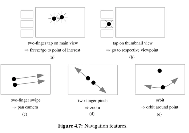
4.3.4 Gesture-based virtual navigation. . . 53
5 Evaluation via User Studies 61 5.1 User Study 1 . . . 61
5.1.1 Task & physical setup . . . 62
5.1.2 Conditions . . . 65 5.1.3 Experimental design . . . 67 5.1.4 Participants . . . 67 5.1.5 Procedure . . . 68 5.1.6 Results. . . 69 5.2 User Study 2 . . . 75
5.2.1 Task & physical setup . . . 76
5.2.2 Conditions . . . 77
5.2.3 Experimental design . . . 78
5.2.4 Participants . . . 78
5.2.5 Procedure . . . 79
5.2.6 Results. . . 80
5.3 Discussion of Studies 1 and 2 . . . 86
5.3.1 Use of features. . . 86
5.3.2 Task performance with interface C vs. interface B . . . 87
5.4 User Study 3 . . . 92
5.4.1 Participants . . . 92
5.4.2 2D drawings in 3D. . . 93
6.2 System Overview . . . 106
6.2.1 Two-view relations and model-based poses . . . 107
6.2.2 Data structures . . . 109
6.3 Tracking . . . 110
6.3.1 Coarse-to-fine feature tracking. . . 112
6.3.2 Model estimation and outlier re-estimation . . . 113
6.3.3 Inserting a new keyframe . . . 114
6.3.4 Relocalizing vs. starting a new track. . . 116
6.4 Mapping . . . 117
6.4.1 Triangulating features . . . 118
6.4.2 Bundle adjustment . . . 118
6.4.3 Merging disjoint tracks . . . 119
6.4.4 Estimation of feature normals . . . 121
6.4.5 Cleaning up residual data . . . 123
6.5 Model Selection . . . 123
6.5.1 Generalized GRIC score for two-view relations . . . 125
6.5.2 GRIC score for absolute pose models . . . 132
6.6 Evaluation . . . 134
6.6.1 Tracking accuracy . . . 136
6.6.2 Qualitative comparison with PTAM . . . 138
6.7 Discussion: Aspects for Further Investigation, Applications & Limitations . . 140
6.7.1 On estimating the probability density function. . . 140
6.7.2 On improving coarse-to-fine matching. . . 141
6.7.3 On tracking robustness. . . 142
6.7.4 On merging of maps . . . 143
6.7.5 On applications & limitations of the hybrid map. . . 144
6.7.6 On model selection and scene segmentation . . . 145
7 Conclusions 146 7.1 Summary. . . 146
7.2 Contributions . . . 148
7.3 Limitations of the Current Implementation . . . 150
7.3.1 Level of detail of the model . . . 151
7.3.2 Static scene . . . 151
7.3.3 Stereo initialization . . . 152
7.3.4 Occlusion of annotations on local side . . . 153
7.4 Opportunities for Future Research . . . 153
7.4.4 Extension to more than two users and other roles . . . 157
3.1 Overview of the proposed concept for remote collaboration.. . . 17
4.1 Prototype 1: Hand-held device for the local user. . . 24
4.2 Prototype 1: View for local and remote user. . . 24
4.3 Prototype 2: System architecture of local and remote user’s system. . . 32
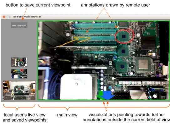
4.4 Prototype 2: Screenshot of the remote user’s interface. . . 41
4.5 Prototype 3: Screenshot of the remote user’s touchscreen interface. . . 48
4.6 Prototype 3: Depth interpretations of 2D drawings. . . 51
4.7 Prototype 3: Navigation features. . . 54
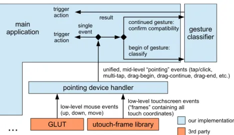
4.8 Prototype 3: Software stack for processing events from pointing devices. . . . 55
4.9 Prototype 3: “Zooming in” via decreasing the field of view and dollying. . . . 56
4.10 Prototype 3: Screenshot during an orbit operation. . . 60
5.1 Study 1: Testbed: view of an airplane cockpit. . . 63
5.2 Study 1: Local user with tablet; overview of the remote user’s interface. . . . 64
5.3 Study 1: Number of tasks completed as a function of the three interfaces. . . . 70
5.4 Study 1: User responses from post-study questionnaire. . . 72
5.5 Study 1: Users’ perceptions of tracking loss.. . . 75
5.6 Study 2: one example out of the 80 individual tasks.. . . 77
5.7 Study 2: Histogram of task times per interface. . . 81
5.8 Study 2: Results from intermediate questionnaires: interface ratings. . . 83
5.9 Study 2: Results from intermediate questionnaires: individual features. . . 84
5.10 Study 2: Results from post-study questionnaire: interface preference. . . 85
5.11 Study 3: Users’ preference among the four different depth interpretations. . . 95
5.12 Study 3: Ratings of two visualization options. . . 96
5.13 Study 3: Ratings of various navigation elements. . . 98
6.1 A combination of 3D structure and panoramic maps as created by our system. 102 6.2 Conceptual overview of the system’s operation. . . 107
6.5 Merging of tracks vs. relocalization. . . 116 6.6 Effect of normal estimation on lifespan of features. . . 123 6.7 Illustration why model selection is difficult. . . 124 6.8 Model selection according to Torr’s GRIC score, illustration of bias towardsH. 130 6.9 Breakdown of timings in tracking thread. . . 135 6.10 Reconstructing a scene in 3D while recovering the camera trajectory. . . 136 6.11 Tracking accuracy with and without model-based tracking. . . 137 6.12 Qualitative comparison of camera trajectories for PTAM and our prototype. . 138
4.1 Characteristics of the three prototype implementations. . . 22
4.2 Prototype 2: Timings of the 3D modeler to process a new keyframe. . . 37
5.1 Study 1: Gender distribution and participant teams. . . 68
5.2 Study 1: Tukey’s posthoc analysis. . . 71
5.3 Study 2: Gender distribution and participant teams. . . 79
5.4 Study 3: Usage of different styles of arrow heads. . . 94
6.1 Estimation algorithms for the four models considered here. . . 113
Introduction
With the widespread deployment of fast data connections and availability of a variety of sensors
for different modalities, the potential of remote collaboration has greatly increased. While the
now ubiquitous video conferencing applications take advantage of some of these capabilities,
they lack the ability to interact with the remote physical environment; the use of video between
remote and local users is limited largely to passively watching disjoint video feeds. This is aptly
summarized by Gelb et al. (2011): “Current systems, however, do a poor job of integrating
video streams [...]. Real and virtual content are unnaturally separated, leading to problems with
nonverbal communication and the overall conference experience.” Thus, teleconference-like
applications have been largely successful when the matter at hand can be discussed verbally or
with the help of purely digital data (such as presentations slides), but they hit severe limitations
when real-world objects or environments are involved.
As effective collaboration often involves sharing, exploring, referencing, or even
manip-ulating the physical environment, tools for remote collaboration should provide support for
human communication, without which communication can be ineffective and frustrating (“If
I could just point to it, its right there,” “if only I could show you how to do it” (Fussell et al.,
2004)). To incorporate these means of communication, researchers have explored various ways
to support remote pointing. However, two of the most common limitations in existing work are
that the remote user’s view onto the scene is constrained to the typically small field of view of
the local user’s camera, and that any support for spatially referencing the scene is contingent
upon a stationary camera, as otherwise the pointers lose their referents.
Advances in computer vision facilitate applications which are to some degree able to
un-derstand where mobile cameras are pointed and what is seen. These new capabilities should
be exploited to enable the remote user to interact with what he/she sees, instead of forcing
him/her to passively watch whatever is in view of the local user’s camera. Further, we suggest
that mobile augmented reality (AR) provides a natural and user-friendly paradigm to
communi-cate spatial information about the scene and to browse an environment remotely. This concept
leads to the following thesis statement:
Integrating computer vision and augmented reality can significantly improve
video-mediated communication and broaden its applicability. In particular,
integrating those technologies enables telecommunication participants to
ef-fectively reference and communicate information about the remote physical
the environment and with off-the-shelf hardware with relatively low sensory
fidelity, making this approach suitable for widespread adoption.
In this dissertation, we support this thesis with contributions on multiple levels:
• We describe a system framework for unobtrusive mobile remote collaboration that inte-grates the physical environment. Our concept does not require specialized equipment or
preparation of the environment and is compatible with a wide range of hardware
con-figurations, including systems that are already ubiquitous (e.g., smartphones) as well as
more advanced immersive systems (Chapter 3).
• We designed three prototypes that implement the aforementioned framework and feature several novel interface elements for unobtrusive mobile telecollaboration in unprepared
environments. Our prototypes use model-free, markerless, expanding visual tracking and
modeling to enable a remote user to provide visual/spatial feedback by means of
world-stabilized annotations that are displayed to a local user in AR. Further, our system enables
decouplingof the local user’s view from the remote user’s view while maintaining live
updates. This gives the remote user control over his/her viewpoint and allows him/her to
study and annotate (and thus direct attention to) parts of the scene that are not currently
in the field of view of the local user. The prototypes’ interfaces include several other
novel features, such as the interpretation of 2D drawings as world-stabilized annotations
in 3D and virtual navigation designed specifically to explore a partially modeled remote
• We conducted user studies to validate the usability of our prototypes and evaluate their benefits over more conventional interfaces, and discuss both quantitative results and
qual-itative observations in detail. To our knowledge, our studies are among the first formal
user studies overall to rely solely on markerless, model-free visual tracking (Chapter 5).
• Lastly, we address one particular limitation of current visual environment modeling, as an important enabling technology of our framework, and describe a conceptual solution
and proof-of-concept implementation. Namely, we describe a novel approach to live
vision-based environment modeling which supports both general (parallax-inducing) and
degenerate (rotation-only) camera motions in environments of arbitrary geometric
com-plexity (Chapter 6).
We will discuss related work in Chapter 2, then present these contributions in the above order.
We conclude in Chapter 7.
Authorship. I am the primary author of all aspects of the work constituting this dissertation.
However, in addition to the guidance of my advisors Tobias H¨ollerer and Matthew Turk on
all parts of this work — and several people to whom we are indebted for providing additional
advice, as expressed in the acknowledgements — several of my colleagues have contributed
to individual parts of this work, as attributed via their co-authorship on the respective
peer-reviewed publications.
Specifically, in the order of appearance of the respective contents in this dissertation: Ben
3 (Sections 4.2 and 4.3) as well as the administration, analysis, and description of user study 2
(Section 5.2); Cha Lee has contributed to the design, administration, analysis, and description
of user study 1 (Section 5.1); and Chris Sweeney and Jon Ventura have contributed to the
formulation, implementation, testing, and description of the tracking and modeling approach
Related Work
2.1
Video-Mediated Communication
Research on video-mediated communication is multifaceted. The body of research includes
investigations on various video configurations (Kraut et al., 1996; Gergle et al., 2004; Fussell
et al., 2000, 2003a) and systems aiming at increasing the level of immersion of teleconferences
by transferring live three-dimensional or perspectively corrected imagery of the participants
(Raskar et al., 1998; Regenbrecht et al., 2004; Sadagic et al., 2001; Kurillo et al., 2008;
Mai-mone and Fuchs, 2011; MaiMai-mone et al., 2013). Collaboration is possible on purely virtual data
(as demonstrated in Sadagic et al., 2001; Regenbrecht et al., 2004; Kurillo et al., 2008), but
There are several AR frameworks that focus on collaborative work and more mobile
in-frastructure (Billinghurst et al., 1998a,b; Butz et al., 1999; Reitmayr and Schmalstieg, 2001).
However, most of these also facilitate collaboration on virtual data only.1
2.2
Spatial References to the Remote Physical Environment
Support for spatial references to the remote physical scene has been an active research topic.
Notable early works include “VideoDraw” (Tang and Minneman, 1991) and the
“DoubleDigi-talDesk” (Wellner and Freeman, 1993).
While many of the above systems focus on symmetric setups (i.e., both participants have the
same equipment and share their own environment to the same degree), further work has been
done on asymmetric local worker/remote expert scenarios (Alem et al., 2011; Bauer et al.,
1999; Fussell et al., 2004; Kurata et al., 2004; Chastine et al., 2008; Ou et al., 2003; Kirk,
2006). These systems typically focus on tasks involving objects in the local worker’s physical
environment (“collaborative physical tasks” (Kirk, 2006)).
Various ways to support the visual/spatial referencing have been studied, for example
re-mote pointers or markers (Bauer et al., 1999; Fussell et al., 2004; Chastine et al., 2008; Kim
et al., 2013), laser pointers (Kurata et al., 2004), drawing onto a live video stream (Ou et al.,
2003; Kirk and Fraser, 2006; Fussell et al., 2004; Gurevich et al., 2012; Kim et al., 2013),
1
Cf. the following quote by Butz et al. (1999): “We present [...] a prototype experimental user interface to a collaborative augmented environment. Users share a 3D virtual space and manipulate virtual objects that represent information to be discussed.”
or directly transferring videos of hand gestures (Kirk and Fraser, 2006; Li et al., 2007; Alem
et al., 2011; Kirk, 2006; Huang and Alem, 2013; Oda et al., 2013). These annotations are then
displayed to the collaborator on a separate screen in a third-person perspective (Fussell et al.,
2004; Huang et al., 2013), on a head-worn display (Bauer et al., 1999; Huang and Alem, 2013;
Oda et al., 2013), or via projectors (Gurevich et al., 2012).
The studies by Fussell et al. (2004), Bauer et al. (1999), Chastine et al. (2008), and Kurata
et al. (2004) are especially pertinent to our work in several regards. In Fussell et al. (2004),
the local user had to assemble a toy robot with guidance from the remote user. The remote
user saw the local user’s workspace by means of a static camera looking over the local user’s
shoulder, while the local user saw the same view on a separate monitor in front of him/her. The
remote user controlled a cursor which was visible on both screens.
In Bauer et al. (1999), the local user was wearing a video-see-through head-worn display
(HWD) and had to solve a puzzle-like task. The remote expert saw the video and controlled a
pointer visible to both of them. To be able to accurately reference objects despite movement
of the local camera, the remote expert could freeze the video. However, they did not employ
any kind of tracking and thus had to freeze the local worker’s view simultaneously to be able
to display the pointer.
In Chastine et al. (2008), the local user was asked to build a structure of wooden blocks,
for which the remote user sees a virtual model in AR. Fiducial marker-based tracking was used
to establish a shared coordinate system for both the virtual model (on the remote user’s side)
pointers by placing additional fiducial markers around the virtual object. Note that in their
setup, the virtual model serves not only as “expert knowledge,” but additionally as surrogate
for the physical model when placing the markers around it.
Kurata et al. (2004) developed a shoulder-worn device with a camera and laser pointer
mounted on a pan-tilt unit which is controlled by a remote user. The remote user thus has some
control over the viewpoint; in addition, their system can build pseudo-panoramic maps (while
the local user is holding still).
However, in order to support spatially referencing objects in the physical world, all of these
systems either assume a static camera (at least for the duration of the relevant interaction), since
otherwise virtual annotations lose their referents (Fussell et al., 2003b, 2004; Bauer et al.,
1999; Kurata et al., 2004; Kirk and Fraser, 2006; Kirk, 2006; Li et al., 2007; Alem et al.,
2011; Gurevich et al., 2012; Huang and Alem, 2013; Kim et al., 2013), or require extensive
equipment and prepared environments to track and thus maintain the annotations’ locations
(Chastine et al., 2008; Oda et al., 2013). Furthermore, in all of these systems, the remote user’s
view into the local environment is either restricted to a static camera (Fussell et al., 2004; Kirk
and Fraser, 2006) or tightly coupled to the local user’s head or body movement (Bauer et al.,
1999; Alem et al., 2011; Kurata et al., 2004; Chastine et al., 2008; Huang and Alem, 2013;
Kim et al., 2013), thus forcing the remote user to constantly re-orient and ask the local user to
hold still (or, in the case of Bauer et al. (1999), enforcing this by freezing both users’ views)
2.3
World-stabilized Spatial References
To overcome the restrictions mentioned above, we leverage computer vision-based tracking
and modeling and the paradigm of AR in order to (a) correctly anchor virtual annotations to
their real-world referents despite a moving camera, and (b) decouple the views of local and
remote user, thus enabling the remote user to explore the environment virtually.
Using world-stabilized annotations for the purpose of remote collaboration has been
envi-sioned before. Davison et al. (2003) describe this goal, and present a Simultaneous
Localiza-tion and Mapping system (cf. SecLocaliza-tion 2.4) for a shoulder-worn robot with camera towards its
realization. Similarly, Reitmayr et al. (2007) discuss tracking of landmarks of varying
com-plexity in order to anchor annotations for the same purpose. Ladikos et al. (2008) present a
tracking system to maintain the location of annotations on planar objects. Also designed for
planar environments, the system by Lee and H¨ollerer (2006) supports not only world-stabilized
drawings, but also viewpoint stabilization for the remote user, which is closely related to our
notion of camera control.
AR-based collaboration between a local (“outdoor”) user and a remote (“indoor”) user was
also discussed by H¨ollerer et al. (1999) and Stafford et al. (2006), albeit using sensor-based
localization and maps and/or 3D models of the local user’s environment rather than real-time
capture and reconstruction.
Sodhi et al. (2013) present a system which is very closely related to our work. They use a
which gives the ability to reconstruct the environment (on the local user’s side) and to
recon-struct and transfer hand gestures (from the remote user’s side) in 3D. In contrast, our system
needs only an off-the-shelf tablet, but uses simpler annotations. Another difference worth
not-ing is the method of scene navigation by the remote user: Sodhi et al. equip the remote user
with a mobile device as well and use the device’s physical movement to navigate the remote
(virtual) environment, while we use virtual navigation. We will contrast the two approaches
with respect to both navigation and input modality in more detail in Sections 4.2.5 and 4.3.1,
respectively. They conducted a usability study reporting results with respect to ease of use,
etc., but no comparative or performance-based evaluation was reported.
The system by Adcock et al. (2013) also reconstructs the environment via active depth
sensors and allows the remote user to control the viewpoint (via a touch interface) and draw
annotations; however, these annotations are displayed using a statically mounted projector.
Further, Jo and Hwang (2013) presented an interactive, fully mobile system which allows
for world-stabilized drawings, albeit only for panoramas (i.e., rotation movements). Two
par-ticular interesting aspects of this work are the physical navigation of the panorama by the
remote user and switching between front and back cameras (upon permission by the local
user).
One alternative to a wearable setup is to use a camera and projective device mounted to
a robot which is controlled by the remote user (Kuzuoka et al., 2000; Gurevich et al., 2012).
However, this requires specialized hardware which needs to be carried around and put in place,
2.4
Vision-based Tracking and Mapping
A key component of our approach is the integration of vision-based tracking and mapping
of the environment to support navigating the environment and anchoring of annotations to it.
Our work is thus related to work in vision-based tracking and mapping, which are important
enabling technologies for the area of AR in general.
Monocular vision-based Simultaneous Localization and Mapping
Simultaneous Localization and Mapping (SLAM) is the problem of determining the pose of
the observer relative to an unknown environment while concurrently creating a model of the
environment (which may have arbitrary geometric complexity) as the observer moves around.
In the case of monocular vision-based SLAM (Davison et al., 2007), the only sensor used to
accomplish this task is a single camera.
Filter-based SLAM systems (Civera et al., 2008a; Davison et al., 2007; Eade and
Drum-mond, 2008) maintain estimates of both camera and feature positions (i.e., the map) in a large
state vector which is updated using Kalman filters in each frame. In contrast, keyframe-based
systems (Klein and Murray, 2007, 2008; Mouragnon et al., 2006) track features in each frame,
but use only selected frames to update their map, typically using bundle adjustment for the
lat-ter. While all aforementioned systems are based on sparse features, Newcombe et al. (2011a)
presented a keyframe-based system that uses dense mapping. They report extremely robust
In both types of systems, the map is designed to store structure-from-motion (SfM) data,
that is, feature positions in 3D that have been triangulated using observations from multiple
viewpoints. Thus, they require parallax-inducing camera motion in order to bootstrap their
map (Davison et al., 2007; Klein and Murray, 2007; Newcombe et al., 2011a), as otherwise,
the features cannot be triangulated and integrated into the map. In some systems (Klein and
Murray, 2007; Newcombe et al., 2011a), the initialization is performed as a dedicated separate
step, and tracking quality crucially depends on the quality of this initialization. Rotation-only
motions are supported only if they are constrained to the already observed part of the scene.
For filter-based systems, an alternative, six-dimensional parametrization of the feature
lo-cations (Civera et al., 2008a) can provide a remedy: Here, rotation-only motions are supported
by admitting features with a depth prior that represents extreme uncertainty and filtering the
features through multiple motion models (Civera et al., 2008b) to constrain their uncertainty.
However, this support comes at a high computational cost: The already high cost of filtering of
each feature point is further increased by doubling the dimensionality of the feature state vector
as well as computing the results for multiple motion models (note that Civera et al. (2008b) use
seven models in each frame).
Panorama tracking and mapping
Like a SLAM system, a panorama tracking and mapping system aims at modeling the
envi-ronment while determining the pose of the camera,2 but in this case, the camera is assumed
to rotate around its optical center, so that only its orientation has to be determined. An early
real-time system is Envisor (DiVerdi et al., 2009). Wagner et al. (2010) describe a system that
operates robustly and in real time on a mobile device.
The tracking system that we developed for our first prototype system (Section 4.1) is
tech-nically equivalent to a panorama tracking system.
2.5
Virtual Navigation
Virtual navigation is a large research area in itself, including a large body of work concerning
3D navigation from 2D inputs (Hanson and Wernert, 1997; Zeleznik and Forsberg, 1999; Tan
et al., 2001; Hachet et al., 2008; Christie and Olivier, 2009; Jankowski and Hachet, 2013;
Bowman et al., 2005; Marchal et al., 2013). Most of these works assume that the scene to
be navigated is known completely (that is, it can be rendered from any viewpoint, such as an
architectural model, the virtual environment in a game, etc.).
2
Depending on the exact interpretation of the word “localization,” one may argue that a panorama tracking and mapping systemisa SLAM system, as advocated by Lovegrove and Davison (2010). This interpretation would render the term “tracking and mapping,” which we chose to refer to the general class following Klein and Murray (2007); Pirchheim and Reitmayr (2011); Wagner et al. (2010), obsolete.
In our context, the scene is only partially reconstructed from image data, with highest
rendering fidelity from a constrained set of previously visited viewpoints, and can be navigated
only based on this reconstruction. In this respect, our work bears similarity in particular with
the work by Snavely et al.’s “Photo tourism” (Snavely et al., 2006) and similar works. However,
while Photo tourism deals with a (potentially large) set of photos in a batch manner and offers
offline navigation, we process a live video in real time and offer live viewing of the evolving
A Concept for Mobile Unobtrusive
Remote Collaboration
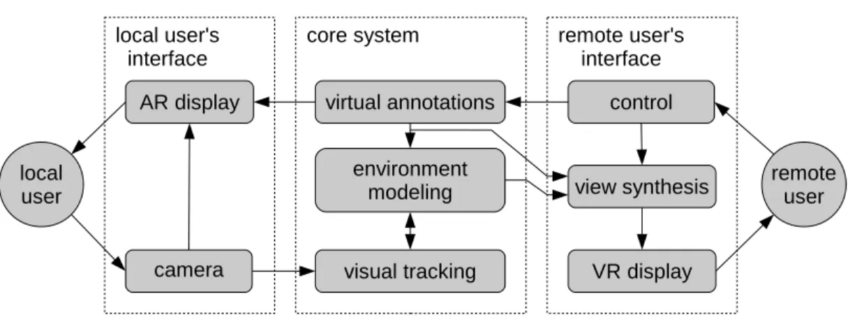
Figure 3.1 illustrates the proposed concept which enables the remote user to explore a physical
environment by means of live imagery from a camera that the local user holds or wears. The
remote user is able to interact with the model fused from these images by creating virtual
annotations in it or transferring live imagery (e.g., of gestures) back.
At the core of the concept is a tracking and environment modeling core, which enables
the system to (1) synthesize novel views of the environment and thus decouple the remote
user’s viewpoint from that of the local user, giving the remote user some control over his/her
viewpoint, and (2) correctly register virtual annotations to their real world referents.
This concept has first been presented in our paper in the proceedings of the ACM
Inter-national Conference on Human-Computer Interaction with Mobile Devices and Services 2012
Figure 3.1: Overview of the proposed concept for unobtrusive, mobile remote collaboration that integrates the physical environment. This figure depicts the situation that the user on the left is situated in the physical task environment and thus assumes the role of the local user, while the user on the right assumes the role of the remote user.
3.1
Local User’s Interface
The local user is assumed to hold or wear a device that integrates a camera and a display
system (e.g., hand-held tablet or head-worn display with camera), which is used to both sense
the environment and display visual/spatial feedback from the remote user correctly registered
to the real world. In the case of a video see-through hand-held device, it acts as amagic lens,
that is, it shows the live camera feed plus virtual annotations. Since a collaboration system has
to aid the user in his/her actual task rather than distract from it, an interface which is simple
and requires a minimal mental load to operate is essential. It should facilitate an active user
3.2
Remote User’s Interface
The remote user is presented with a view into the local user’s environment, rendered from
im-ages obtained by the local user’s camera. The remote user can place annotations that will be
dis-played to both users, correctly registered to their real-world referents from their respective point
of views. Annotations may include point-based markers, more complex three-dimensional
an-notations, drawings, or live imagery (e.g., of hand gestures).
In the simplest case, the remote user’s viewpoint may be restricted to being identical to the
local user’s current camera view. In this case, no further image synthesis is needed. Ideally,
however, the remote user should be able to decouple his/her viewpoint and control it
indepen-dently, as far as supported by the available imagery of the environment.
If the system allows for decoupled views, it is important that only theviewpoint is
decou-pled; the video is still synthesized and updated from live images in order to enable consistent
communication. (For example, in the case of our first prototype system, the effect of this can be
observed in Figure 4.2(b): although the viewpoints are different, the remote user can observe
how the local user is pointing to a control element on the panel in front of him.)
3.3
Visual Tracking & Environment Modeling
We assume that the environment may be completely unknown prior to the start of the system,
that is, we do not require any model information. While using model information bears the
in some way prior to the task, which either severely limits the generality of the system or puts
a burden on the user.
Instead, we assume that the system starts with no prior knowledge about the scene and
builds up an internal representation on the fly, which automatically expands to include new
areas as the camera moves. This does not preclude the use of additional data that may be
available from online sources — cf. the “Anywhere Augmentation” paradigm (H¨ollerer et al.,
2007) — to provide additional information should a specific location or object have been
iden-tified, but it means that our system will not require such data (in particular, no model of the
environment), in order to operate. Our concept is compatible with environment modeling
sys-tems of different levels of flexibility and generality, including panorama mapping and SLAM.
If admissible by the application, other sensors such as active depth cameras could also be used
(Newcombe et al., 2011b).
3.4
Hardware
We note that only very few requirements for the hardware that this concept could run on were
specified thus far. Indeed, this concept is compatible with a wide range of hardware systems,
including systems that are already ubiquitous (e.g., smartphones), as well as more immersive
systems which may serve specialized applications or become more wide-spread in the future.
external factors such as cost, market penetration and task- or environment-specific
considera-tions.
In particular, our concept is compatible with various types of displays for the local user,
including smartphones or tablets, head-worn displays (used in the context of remote
collabo-ration for example by Bauer et al. (1999); Huang and Alem (2013); Oda et al. (2013)), as well
as projective displays (used in the context of remote collaboration for example by Gurevich
et al. (2012)). To demonstrate that our concept does not hinge on benefits of more immersive
technology and is suitable for wide-spread adoption, we used hand-held tablets in this work.
Likewise, the remote user’s interface could consist of a standard PC interface with screen,
mouse, keyboard; a touchscreen; a head-worn (and -tracked) virtual reality (VR) display; or a
multitude of other VR displays. With the system prototypes described in Chapter 4, we explore
Design of Interfaces & Implementation of
Prototype Systems
In this chapter, we describe the design and implementation of three prototype systems that
im-plement the concept presented in Chapter 3. From Prototype 1 to 3, they describe an evolution
from an initial proof-of-concept system to a flexible, feature-rich mobile system that allows
untrained users to interact with the remote environment and communicate spatial information.
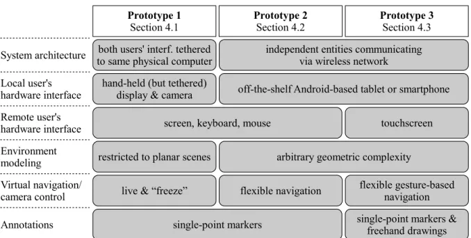
Important characteristics of and differences between the three prototypes are summarized in
Table 4.1.
Prototype 1 (Section 4.1) is an initial proof-of-concept implementation. It is not actually
net-worked, but uses two interfaces connected to the same physical computer. It is a complete, but
in several ways the simplest or least immersive implementation of our concept. Most notably,
the remote user’s camera control is limited to a “freeze” (and “un-freeze”) feature.
Techni-cally, it is limited in generality in one particular aspect: its tracking and modeling capabilities
Table 4.1: Characteristics of the three prototype implementations.
movements, but not with general camera motion in general environments. With the user study
described in Section 5.1, we will show that even with this low-immersion implementation, our
concept provides significant benefits in a remote collaborative task.
Prototype 2 (Section 4.2) is a more general and feature-rich implementation. In particular,
(1) it consists of two stand-alone entities communicating via wireless network, (2) it operates in
environments of arbitrary geometric complexity, and (3) it enables the remote user to explore
the remote scene via a set of virtual navigation controls. This prototype is evaluated via a
Prototype 3 (Section 4.3) builds upon Prototype 2, sharing much of the underlying system
infrastructure and architecture, but provides a more intuitive and immersive user experience
for the remote user, and improves individual interface aspects by building upon user feedback
from the second study. In particular, we incorporated a touchscreen interface to allow more
direct interaction, added support for free-hand drawings as more flexible and expressive
anno-tations, and added gesture-based virtual navigation. Adding these new elements involved new,
unique design challenges, which are evaluated via a qualitative user study to be described in
Section 5.4.
4.1
Prototype 1
The prototype presented in this section has first been described in our paper in the proceedings
of the ACM International Conference on Human-Computer Interaction with Mobile Devices
and Services 2012 (Gauglitz et al., 2012a).
4.1.1
Local user’s interface
As hardware interface for the local user, we decided to use a hand-held tablet screen, since
we wanted to show that benefits can be achieved using hardware setups that are already in
widespread deployment. This prototype being the initial proof-of-concept system, for ease of
implementation and flexibility with respect to the hardware components to be used, we use a
Figure 4.1: Hand-held device for the local user: 10” USB tablet screen with camera mounted on back.
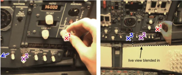
(a) view for local user (b) view for remote user
Figure 4.2: View for local and remote user. The remote user’s viewpoint (b) is frozen, but the live video frame is — correctly registered with the frozen frame — blended in, such that the remote user can still observe the local user’s actions. The remote user has set three markers in his view. Two are inside the local user’s current field of view (a), the third lies outside his view on the left, as indicated by the (accordingly colored) arrow on the left. Note that the view is correctly tracked (as apparent from the correctly registered frames and markers) despite significant occlusion from the local user’s hand.
tablet computer, and all computations are executed on the connected PC. However, we do not
make use of a GPU and the computation-intensive part (i.e., the tracking with the template
matching core, cf. Section 4.1.3) is very similar to the tracking system by Wagner et al. (2009),
which operates in real time on a 2009 smart phone. Thus, our system could be implemented on
a mobile device (such as a light-weight tablet or smartphone) given appropriate optimizations.
When tracking is lost and needs to be recovered, the local user sees a large red ‘X’ across
the screen to indicate that tracking is lost and hence virtual annotations cannot be drawn. By
pointing back to a previously seen location, the user can help the system to recover tracking
(cf. Section 4.1.3). Even if tracking is lost, the live video feed is not interrupted and the local
user may continue to work.
As virtual annotations, our prototype supports point-based markers which the remote user
controls. They are displayed to both users in their respective views as an ‘X’ anchored to the
real world, with a number attached to it and additionally color coded to disambiguate between
multiple markers. When a marker is set outside the current view or moves outside the current
view, a correspondingly colored arrow appears on the border of the screen pointing towards the
marker’s location (see Figure 4.2(a)). (Cf. (Baudisch and Rosenholtz, 2003; Gustafson et al.,
4.1.2
Remote user’s interface
The remote user is presented with a view of the local user’s environment and can place markers
by clicking into this view (Figure 4.2(b)).
We provided one particular feature that allows control over the remote user’s viewpoint: the
remote user can “freeze” (and un-freeze) his/her viewpoint at any time. Despite its simplicity,
this feature allows decoupling of the remote view from local movement, and thus enables for
example precise clicking on objects despite the movement of the camera on the local user’s
side. This feature resembles the “Frame & Freeze” technique by G¨uven et al. (2006), which
was developed for a mobile AR user to interact with his own view.
The local user’s screen isnotaffected by the freezing and remains “live” at all times. Using
visual tracking, the remote user’s view is still registered to the local user’s live view. Therefore,
when markers are set, they immediately appear at the correct position with respect to the world
on both the local and remote views. The remote user can return to the live view at any time by
right-clicking again, and the view transitions back to the live view, animated by interpolating a
few frames between the two viewpoints.
Note that rather than freezing the remote user’svideo frame— this would have the crucial
disadvantage that the remote user would not receive any visual updates and could not observe
the local user’s action — we freeze theviewpoint of the remote user and display a transparent
image of the live stream on top of the remote user’s frozen view, correctly registered with the
view, the remote user sees a half-transparent hand correctly indicating the object of interest.
Blending the two frames, rather than displaying only the warped live frame, has the advantage
that the initial frozen frame remains visible and stable even if the warped view becomes jittery
or blurry (due to jittery tracking, motion blur, or extreme warping angles), and it reduces
arti-facts along the border of the live frame. The blended view with the local user’s half-transparent
hand (Figure 4.2(b)) bears noteworthy resemblance to the blended video feeds in several related
systems (Tang and Minneman, 1991; Wellner and Freeman, 1993; Kirk and Fraser, 2006), but
these systems require a static setup with known camera pose.
4.1.3
Visual tracking & environment modeling
As visual tracking system we used a multi-level, active search patch tracker with normalized
cross-correlation (NCC)-based template matching and keyframe-based recovery, inspired by
the systems of Wagner et al. (2009) and Klein and Murray (2008). In preliminary
investiga-tions, this algorithm was found to perform favorably in terms of speed/robustness trade-off
compared to several image alignment- and other feature-based algorithms.
As postulated by our concept, we do not use any model information; that is, the environment
is completely unknown prior to the start of the system. Instead, our system builds up an internal
representation on the fly which automatically expands to include new areas as the camera
The tracking system could enable further features that may improve the collaboration. Most
notably, it could effectively increase the field of view of the remote user by displaying the
entire map collected by a panning camera. However, we decided to make only minimal use of
the tracking by only world-referencing annotations and the remote user’s viewpoint, to allow
evaluation of these features in particular.
Details of the Tracking Algorithm. From the first frame, the tracker creates an image
pyra-mid by half-sampling the image twice. On each level, keypoints are detected with the FAST
corner detector (Rosten and Drummond, 2006), and a subset that is spatially well-distributed
across the image is selected with the algorithm described in Gauglitz et al. (2011). Those
keypoints constitute the features that are tracked and based on which the camera viewpoint
(modeled as homography) is estimated for each frame.
Each incoming frame is projected back to the initial viewpoint, taking the previous frame’s
estimated homography as prior estimate (such that the patch tracker has to be robust to the
distortion between two subsequent frames only). Then, each feature’s new position is
estab-lished by NCC-based template matching of an 11×11 pixel image patch. This is done for the top-most (smallest) image level first, then the homography is re-estimated from the putative
feature correspondences using RANSAC (Fischler and Bolles, 1981) and used to project the
features into the next level. This ensures robustness to relatively large inter-frame movements
despite a small template matching area. We used a radius of 5 pixels on the top-most level,
As new areas come into view, features are detected in those areas as well and added to
the internal map by storing their position and NCC template with respect to the initial frame’s
coordinate system.
Tracking Loss & Recovery. We implemented a recovery algorithm similar to that of Klein
and Murray (2008). In certain intervals and if tracking quality is deemed good (as determined
by the fraction of inliers found by RANSAC), the system creates a keyframe by downsampling
the current frame to 80×60 pixels, blurring it with a Gaussian kernel (σ = 1.5), and storing it together with the current pose information.
The system declares tracking to be lost if RANSAC fails to find a certain fraction of visible
features (25%) that agree on one pose estimate. If tracking is lost, each new frame is also
downsampled and blurred, and the NCC score between this frame and all stored keyframes is
computed. The keyframe with the highest score is then aligned to the downsampled current
frame. During this image alignment step, the homography is restricted to be affine, which
increases both the speed and the convergence rate. The refined pose of the stored keyframe
is then fed back into the tracking algorithm. If RANSAC is able to again find a sufficiently
large fraction of inliers among the feature correspondences, tracking is assumed to be restored
successfully; otherwise, the recovery algorithm is run again with the next frame.
When It Is Not Necessary to Recover Tracking. Unless tracking recovery succeeds
previously seen location. This is a distraction from his actual task, and thus should only be
done if necessary. Therefore, it is important to understand when recovery is dispensable and
design the system appropriately.
In our system, tracking is needed in two cases: when annotations (markers) are present,
and when the remote user has frozen his/her viewpoint. If neither is the case, tracking is not
currently needed and hence the user should not be bothered with requests to recover it. In
this case, recovery is attempted only for a maximum of 10 frames. If unsuccessful, tracking
is simply reset and re-initialized with the current frame. If, however, tracking is needed to
maintain currently active markers or the registration with the remote user’s frozen viewpoint,
recovery is attempted for much longer, asking the user to help with recovery by displaying the
red ‘X’ if needed. If recovery is not successful after 240 frames, it is assumed that the user
does not want or is unable to recover tracking, and the tracking is reset.
Real-time Performance. Overall, this system is fast enough to operate in real time — the
framerate is limited by the camera (30 Hz) and not by the tracking algorithms — and is robust
enough to be used by our study participants without any specific instructions, while coping with
(or successfully recovering from) free camera movement, motion blur, specular reflections, and
4.2
Prototype 2
While Prototype 1 is a complete proof-of-concept implementation of our concept — and was
rated very favorably by users, as we will describe in Section 5.1 in detail — it suffers from
one particular technical limitation (namely, it can operate only in planar environments) and
provides only a very simplistic camera control for the remote user, which however is one of
the key components of our concept. We addressed both limitations with the implementation
of the prototype described in this section. As a further advance denoting a shift from a
proof-of-concept to a fully operational system, this prototype consists of two stand-alone entities
communicating via wireless network; the local user’s device is an off-the-shelf Android-based
smartphone or tablet.
This prototype will be published in the proceedings of the ACM Symposium on User
In-terface Software and Technology 2014 (Gauglitz et al., 2014a).
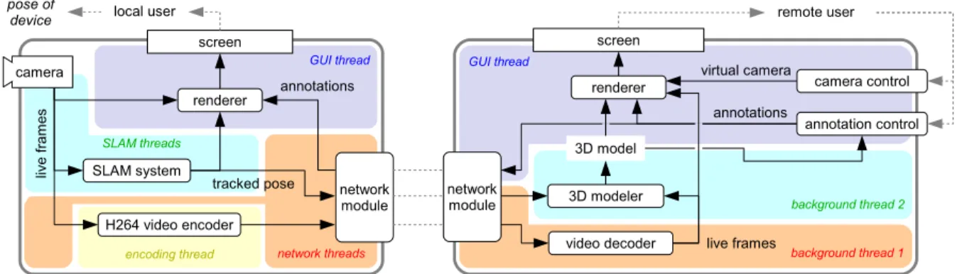
Figure 4.3 shows an overview of the system architecture of both the local user’s and the
remote user’s system. Since device hardware (camera and display), network communication,
real-time processing, and background tasks are involved, both systems employ a host of
com-ponents and threads.
4.2.1
Local user’s system
The local user’s interface, running on a lightweight tablet, is intentionally simple. As in
Figure 4.3: System architecture of Prototype 2 including the local user’s system (left; running on an Android-based lightweight tablet or smartphone) and the remote user’s system (right; running on a commodity PC with Ubuntu). The main components are described in the text in detail.
user’s own view plus AR annotations, i.e., a classic magic lens. The only control the user exerts
during its operation is by manipulating the position and orientation of the device.
Under the hood, the system runs a SLAM system and sends the tracked camera pose along
with the encoded live video stream to the remote system. The local user’s system receives
information about annotations from the remote system and uses this information together with
the live video to render the augmented view.
As in Prototype 1, tracking can get lost, which is communicated to the user via a red border
around the screen. The SLAM system continuously tries to relocalize until successful; the user
can help this effort by going back to a pose in which tracking is known to work. The live video
transmission continues despite tracking loss.
The system is implemented as an Android app, running on several state-of-the-art Android
Qual-comm Snapdragon S4 Pro with 1500 MHz Krait quad core CPU. The core SLAM
implementa-tion, including access to the live camera frames and support for rendering them, was provided
to us for this work by Qualcomm, Inc. Communication with the SLAM system, handling of
the raw image data, and rendering are implemented in C/C++, while higher-level app
struc-ture, user interface, and network communication are implemented in Java, with data exchange
between the two layers via JNI. The live frames are encoded as a H.264 video stream. A
mini-mal HTTP server streams the data (encoded video, tracked camera pose, and other meta-data)
upon request from a remote connection, and manages remote requests for insertion/deletion of
annotations (encoded as HTTP requests).
The system operates at 30 frames per second. We measured system latencies using a camera
with 1000 fps which observed a change in the physical world (a falling object passing a certain
height) as well as its image on the respective screen. The latency between physical effect and
the local user’s tablet display — including image formation on the sensor, retrieval, processing
by the SLAM system, rendering of the image, and display on the screen — was measured as
205±22.6 ms (average and standard deviation over a series of measurements).
4.2.2
Remote user’s system: Overview & Architecture
The remote user’s interface, running on a commodity PC (without high-end GPUs or such),
starts off as a live video stream, but is augmented by two controls, thecamera controland the
The system consists of five main modules — network module, 3D modeler, camera control,
annotation control, and renderer — and the framework to hold them together. Due to this
mod-ular architecture, different implementations for each module can be readily swapped in and out
upon the start of the program via command line arguments. This flexibility enabled several use
cases:
1. For comparing our interface against two baseline interfaces in our user study
(Sec-tion 5.2), we simply replaced the respective components with simpler ones;
2. For development and testing, we also implemented modules that load virtual 3D models
(instead of modeling from live video) and allow for other types of camera control;
3. Prototype 3 utilizes the same architecture and was realized by implementing appropriate
new modules (Section 4.3);
4. Due to this flexibility, the overall system was used not only to implement and evaluate
the prototypes presented here, but was also used as platform for other studies, published
in Nuernberger et al. (2014), targeting the evaluation of other interface elements.
Here, we describe the module implementations that constitute our Prototype 2.
Using the same setup as above (Section 4.2.1), the latency between physical effect and
the remote user’s display — including image formation on the local user’s sensor, retrieval,
processing by the SLAM system, video encoding, transmission via wireless network, video
4.2.3
Remote user’s system: Network module
The network module receives the data stream from the local user’s device, sends the incoming
video data on to the decoder, and finally notifies the main module when a new frame (decoded
image data + meta-data) is available.
4.2.4
Remote user’s system: 3D modeler
From the live video stream and associated camera poses, we construct a 3D surface model
on the fly as follows. We select keyframes based on a set of heuristics (tracking quality, low
device movement, minimum time & translational distance between keyframes), then detect
and describe features in the new frame using SIFT (Lowe, 2004). We then choose the four
closest existing keyframes, match against their features (one frame at a time) via an
approxi-mate nearest neighbor algorithm (Muja and Lowe, 2009) and collect matches that satisfy the
epipolar constraint (which is known due to the received camera poses) within some tolerance
as tentative 3D points. If a feature has previously been matched to features from other frames,
we check for mutual epipolar consistency of all observations and merge them into a single 3D
point if possible; otherwise, the two 3D points remain as competing hypotheses.
Next, all tentative 3D points are sorted by the number of supporting observations and are
accepted one by one unless one of their observations has been previously “claimed” by an
already accepted 3D point (which, by construction, had more support). We require at least four
largest 3D distances to their two nearest neighbors. The algorithm is thus robust to even large
fractions of mismatches from the stereo matching stage.
To obtain a surface model from the 3D point cloud, we implemented the algorithm by
Hoppe et al. (2013): First, a Delaunay tetrahedralization of the point cloud is created. Each
tetrahedron is then labeled as “free” or “occupied,” and the interface between free and occupied
tetrahedra is extracted as the scene’s surface. The labeling of the tetrahedra works as follows:
A graph structure is created in which each tetrahedron is represented by a node, and nodes of
neighboring tetrahedra are linked by edges. Each node is further linked to a “free” (sink) node
and an “occupied” (source) node. The weights of all edges depend on the observations that
formed each vertex; for example, an observation ray that cuts through a cell indicates that this
cell is free, while a ray ending in front of a cell indicates that the cell is occupied. Finally, the
labels for all tetrahedra are determined by solving a dynamic graph cut problem. For details on
how the edge weights are computed we refer the reader to Hoppe et al. (2013).
We refined Hoppe et al. (2013)’s algorithm by taking the orientation of observation rays to
cell interfaces into account, which reduces the number of “weak” links and thus the risk that
the graph cut finds a minimum that does not correspond to a true surface.
As Hoppe et al. describe, both updating the graph costs and solving the graph cut can be
implemented in an incremental manner, with cost almost independent of the overall model
size. As these steps were found to take up a negligible amount of time in our application (cf.
Table 4.2), for simplicity we did not even implement the incremental algorithm. Nonetheless,
# of keyframes in model 1–10 11–25 >25 Keypoint detection 32±2 32±3 34±2 Keypoint description 904±124 868±144 795±167 Stereo matching 121±59 166±38 153±45 Merging & filtering of vertices <1±1 5±1 9±2 Updating tetrahedralization <1±1 2±2 3±3 Calculating graph costs 10±6 51±14 128±28 Solving graph cut <1±<1 1±<1 1±1 Extracting & smoothing surface 4±8 9±21 21±9 Total time 1082±140 1159±175 1201±208
Table 4.2: Average timings of the 3D modeler to process and integrate one new keyframe into the model, running on a single core of a 3 GHz Intel i7 CPU with 4 GB RAM. All times are given in milliseconds, with associated standard deviations. Incorporating all logs from the user study to be discussed below, the data in the three columns are based on 300, 429, and 481 keyframe integrations, respectively.
within 1-1.5 seconds (cf. Table 4.2), which is easily fast enough for our purposes, as it is
smaller than the interval at which keyframes are added on average. Currently, the vast majority
of the time is taken up by the keypoint description, which is independent of the model size. If
necessary, the computation could be significantly sped up by using a more efficient descriptor
implementation or algorithm and/or implementing the incremental graph update. Thus, the
overall modeling algorithm is highly scalable to environments much larger than demonstrated