Water Body Temperature Model for
Assessing Climate Change Impacts
on Thermal Cooling
Ken Strzepek, Charles Fant, Yohannes Gebretsadik, Megan Lickley, Brent Boehlert,
Steven Chapra, Eric Adams, Andrzej Strzepek and C. Adam Schlosser
Report No. 280
May 2015
The MIT Joint Program on the Science and Policy of Global Change combines cutting-edge scientific research with independent policy analysis to provide a solid foundation for the public and private decisions needed to mitigate and adapt to unavoidable global environmental changes. Being data-driven, the Program uses extensive Earth system and economic data and models to produce quantitative analysis and predictions of the risks of climate change and the challenges of limiting human influence on the environment—essential knowledge for the international dialogue toward a global response to climate change.
To this end, the Program brings together an interdisciplinary group from two established MIT research centers: the Center for Global Change Science (CGCS) and the Center for Energy and Environmental Policy Research (CEEPR). These two centers—along with collaborators from the Marine Biology Laboratory (MBL) at Woods Hole and short- and long-term visitors—provide the united vision needed to solve global challenges.
At the heart of much of the Program’s work lies MIT’s Integrated Global System Model. Through this integrated model, the Program seeks to: discover new interactions among natural and human climate system components; objectively assess uncertainty in economic and climate projections; critically and quantitatively analyze environmental management and policy proposals; understand complex connections among the many forces that will shape our future; and improve methods to model, monitor and verify greenhouse gas emissions and climatic impacts. This reprint is one of a series intended to communicate research results and improve public understanding of global environment and energy challenges, thereby contributing to informed debate about climate change and the economic and social implications of policy alternatives.
Ronald G. Prinn and John M. Reilly, Program Co-Directors
For more information, contact the Program office:
MIT Joint Program on the Science and Policy of Global Change Postal Address:
Massachusetts Institute of Technology 77 Massachusetts Avenue, E19-411 Cambridge, MA 02139 (USA) Location:
Building E19, Room 411 400 Main Street, Cambridge Access:
Tel: (617) 253-7492 Fax: (617) 253-9845
Email: globalchange@mit.edu
1
Water Body Temperature Model for Assessing Climate Change Impacts on Thermal Cooling
Ken Strzepek*†, Charles Fant*, Yohannes Gebretsadik‡, Megan Lickley*, Brent Boehlert§, Steven Chapra**, Eric Adams* Andrzej Strzepek* and C. Adam Schlosser*
Abstract
We develop and test a physically based semi-Lagrangian water body temperature model to apply climatological data and thermal pollution from river-based power plants to historical river flow data in order to better understand climate change impacts on surface water temperature and thermal power plant withdrawal allowances. The model is built for rapid assessment and use in Integrated Assessment Models. We first test the standalone model on a 190km river reach, the Delaware River, where we have detailed flow and temperature data. An R2 of 0.88 is obtained on hourly data for this initial test. Next, we integrate the standalone temperature model into a series of models— rainfall-runoff model, water demand model, water resource management model, and power plant uptake and release model—for the contiguous USA (CONUS), with about 19,000 segments total. With this system in place, we then validate the standalone water temperature model within the system for 16 river stations throughout the CONUS, where we have measured daily temperature data. The model performs reasonably well with a median R2 of 0.88. A variety of climate and emissions scenarios are
then applied to the model to test regions of higher vulnerability to river temperature environmental violations, making use of output from two GCMs and six emissions scenarios focusing on projections out to 2050. We find that the two GCMs project significantly different impacts to water temperature, driven largely by the resulting changes in streamflow from the two models. We also find significantly different impacts on the withdrawal allowed by thermal power plants due to environmental regulations. Potential impacts on generation are between +3% and -4% by 2050 for the unconstrained emissions case and +3.5% to -2% for the stringent GHG mitigation policy (where 1% is equivalent to 32 TWh, or about 3 billion USD/year using 2005 electricity prices). We also find that once-through cooling plants are most vulnerable to climate change impacts, with summer impacts ranging from -0.8% to -6% for the unconstrained emissions case and +2.1% to -3.7% for the stringent GHG emissions case.
Contents
1. INTRODUCTION ... 2
2. DATA AND METHODS ... 3
2.1 Climate Scenarios ... 4
2.2 Runoff Model ... 6
2.2.1 Water Demands ... 6
2.3 Water Resources Management Model ... 7
2.4 Model of Water-body Temperature ... 8
2.4.1 River Network ... 8
2.4.2 River Geometry ... 8
2.4.3 Heat Budget Model ... 9
* Joint Program on the Science and Policy of Global Change, Massachusetts Institute of Technology, MA, USA.
† Corresponding author (Email: strzepek@mit.edu).
‡ UNU - World Institute for Development Economics Research, Helsinki, Finland.
§ Industrial Economics, Inc., Cambridge, MA, USA.
2
2.5 Power Plant Model ... 11
3. MODEL VALIDATION ... 13
3.1 The Delaware River ... 14
3.2 Multi-HUC Model Testing ... 16
4. RESULTS ... 17
4.1 Baseline ... 17
4.2 Future Changes ... 19
4.3 Valuation of Mitigation Benefits ... 23
5. CONCLUSION ... 25
6. REFERENCES ... 26 1. INTRODUCTION
River temperatures are critical for maintaining both the integrity of the aquatic ecosystem, and the cooling capacity for thermoelectric power production. Temperature is often referred to as the most critical water parameter as it influences the growth, reproductivity and metabolism of fish, the ecosystem composition and productivity, the level of oxygen and carbon dioxide uptake, and the rate of chemical reactions (Brungs et al., 1977; MacLeod and Pessah, 1973; Graham, 1949). Temperature is also an important parameter for the production of energy in the United States, as power plants require cold water for cooling purposes and efficient production of energy.
Presently, 91% of energy production in the United States comes from thermoelectric power plants (nuclear, coal, natural gas, petroleum) (EIA, 2013) and accounts for just over 40% of total freshwater withdrawals (Kenny et al., 2014). Since many of the withdrawals are used for cooling purposes, the effluent water from power plants is much warmer than the natural river
temperature.
Due to the harmful impacts that warm river temperatures can have on fish, water temperature has been regulated under the Federal Water Pollution Control Act (a.k.a. the Clean Water Act) in Sections 316a and 316b. Though restrictions change from state to state, generally river
temperatures are restricted to a 2.8°C temperature increase from a pollution source (once fully mixed), with a fully mixed temperature not exceeding upper limits ranging between 23°C and 29°C, location dependent. Until recently, power plants have adapted to meet these restrictions with technological improvements such as cooling towers or cooling ponds. However, in 2012, despite these improvements, power production suffered due to increased drought and heat waves. The Millstone nuclear power plant, for example, was forced to shut down due to water in Long Island Sound being too warm to cool the plant. In Illinois that year, cooling ponds were
exceeding 37°C and the EPA granted special permission for plant operations despite exceeding temperature restrictions and water withdrawal limitations. As climate change worsens over the coming decades, we can expect a higher frequency of these events. The IPCC (2014) reports that we should expect warmer air temperatures, prolonged droughts, and decreased snow packs and flows, all of which would negatively impact the availability of cold freshwater. The extent of these impacts on power production, however, remains unclear.
There are many studies that provide some useful insight into the impacts of climate on river temperature and/or power production. Earlier research provides simple relationships between air temperature, elevation and the resulting river temperature (Stefan and Preud’homme, 1993;
3
Walker and Lawson, 1993). While these methods are still useful in their simplicity, more
complete and dynamic models have since been developed. Among these models there is a broad range of spatial and temporal resolution as well as complexity in terms of hydrological and atmospheric interactions with water temperature. There are now multiple global, large basin routing models (van Vliet et al., 2012a; Olivera et al., 2000; Ngo-Duc et al., 2007) which use variable velocity to model river runoff in the worlds 20 largest rivers. There are more highly resolved and physically complex models like Gooseff et al. (2005), which looks at climate change impacts on a river downstream of a small reservoir and accounts for kinematic wave flow routing, atmosphere and stream-bed heat exchange fluxes. This allows for a more in-depth analysis at a single location. Herb and Stefan (2010) includes wetlands and groundwater along with atmospheric heat transfer, and Yearsley (2012) uses a grid-based approach and includes propagation of uncertainty to model climate impacts on stream temperature.
With the exception of van Vliet et al. (2012b), much of the literature on climate impacts on power systems is limited to individual plant analysis. Förster and Lilliestam (2010) model the range of thermo power production constraints under changes in stream temperature and flow. Chandel et al. (2011) model the impacts of climate policy and a CO2 price on freshwater use in thermoelectric power production. The networked aspect of river modeling is especially important for modeling thermal pollution as it is cumulative, i.e. upstream plants can impact downstream withdrawal temperatures. The methods used in van Vliet et al. (2012b), however, account for climate impacts on a networked river model in order to assess broad scale energy production vulnerability in Europe and the U.S. They incorporate an electricity production model to account for thermal pollution and loss of electricity production as a result of climate change. They also use a temperature change across the heat exchanger of 3°C, which is low—typical temperature changes are closer to 11–12°C (Adams and Harleman, 1979).
In this paper, we present a physically based networked semi-Lagrangian river temperature transport model for the United States that runs hourly at an 8-digit HUC scale and includes thermal discharge from energy sources. Our standalone water temperature model follows many other methods such as Yearsley (2009), and we’ve adapted this method to look at specific water and energy systems. The model is intended to fit efficiently into an integrated assessment model framework for climate change impact studies. Consequently, we integrate our water temperature model into a series of models to quantify the climate change impact on power plant withdrawal and release, enforcing conservative environmental regulations. These data and methods are described in Section 2. In Section 3, the model validation is presented. In Section 4, we present the results of the climate change impact analysis. Finally, in Section 5, the main conclusions of the study are discussed.
2. DATA AND METHODS
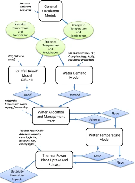
In this section, we describe the full suite of models used in this analysis (summarized in Figure 1). First, a series of climate and emissions scenarios are developed to understand the impacts of mitigation, climate sensitivity, and GCM model structure. Second, a rainfall-runoff
4
model is employed to estimate the impacts of changes in climate to changes in surface water supply. Third, we develop estimates of changes in water demands, which respond to changes in population and climate. Fourth, these data are integrated into a water resource management model that systematically simulates surface-water allocation as well as reservoir storage and release. Fifth, these managed flows and reservoir volumes are input into the water temperature model. Finally, a physically based rule-of-thumb model of thermal power plant uptake and release is developed and implemented to estimate the power generation impact.
Figure 1. Model overview diagram.
2.1 Climate Scenarios
For the baseline climate scenario, the model is forced by Princeton University’s publicly available Global Meteorological Forcing Dataset for land surface modeling (Sheffieldet al., 2006) specified at a 0.5° ! 0.5° resolution for 1980–2008. We spatially interpolate the climatological data within the 0.5°! 0.5°grid to each HUC’s centroid. We assume uniform
!"#"$%&' ()$*+&%,-#' .-/"&0' !"#$%&'()*+',-.% +/0*1% 1%)#2%&&'1+#-3' .-/"&' (45167855' 9)0:-$)*%&' ;"<="$%:+$"' %#/' >$"*)=):%,-#' (?%#@"0')#' ;"<="$%:+$"' %#/' >$"*)=):%,-#' 2*,-3*0% "4'(('*0(% 5,60-+'*(% 5*'.%,&-+-,)6+'(3,($%!"#$% 7+*8%8&60*.*9:$%;,$%;:$% 8*8/.-3*0%8+*<6,3*0(% A%:"$'B"<%#/' .-/"&' C&-D0' 1+#-3' B"<%#/' >$-E"*:"/' ;"<="$%:+$"' %#/' >$"*)=):%,-#' =6(6+>*'+($% &:?+*8*@6+$%@-)6+% (/88.:$%A*@%+*/309% F-&+<"0' A%:"$'G&&-*%,-#' %#/'.%#%@"<"#:'' AHG>' H&"*:$)*):I' !"#"$%,-#' 5<=%*:0' A%:"$';"<="$%:+$"' .-/"&' #&6+4-.%!*@6+%!.-0)% ?-)-B-(6C%,-8-,'):$% ,-8-,'):%D-,)*+$% .*,-3*0($%D/6.$% ,**.'09%):86(%% ;?"$<%&'>-D"$' >&%#:'6=:%J"'%#/' 1"&"%0"' C&-D0' ;"<=K'
5
conditions throughout the entire HUC. Daily minimum and maximum air temperature, Tmin and
Tmax, respectively, are defined on a 1°× 1°scale and we adjust the interpolation accordingly. Climate projections and future time periods (henceforth referred to as eras) allow us to estimate the benefits of GHG mitigation and how those benefits evolve over time. First, we develop a control scenario that represents present day climate conditions but includes population projections. We then alter the control scenario input data by changes in future climate, and measure the resulting changes in output across the various scenarios. Detailed descriptions of the global GHG mitigation scenarios used in this analysis, along with a comparison to the
representative concentration pathways (RCPs) and global climate projections, are provided in Paltsev et al. (2013) and Waldhoff et al. (2014). In short, three emission scenarios are used: a reference (REF) or ‘business as usual’, and two scenarios representing futures with policies that limit global GHG emissions such that total radiative forcing levels in 2100 are stabilized at 4.5 W/m2 (Policy 4.5) or 3.7 W/m2 (Policy 3.7). The REF scenario has a total radiative forcing of 10.0 W/m2 in 2100. Using the IPCC simplified equations, the REF has a total radiative forcing of 8.8 W/m2, and is therefore similar to representative concentration pathway (RCP) 8.5. The base framework used to project future climate, the Community Atmospheric Model linked with the MIT Integrated Global Systems Model (IGSM-CAM), is presented in Monier et al. (2013, 2014), which also provide a summary of the simulations and details on the regional projections of climate change used in this study. Since the IGSM-CAM study only considers one GCM, the IGSM pattern scaling approach was used to develop a balanced set of regional patterns of climatic change for CONUS (see Monier et al. 2014 for methodological details). This approach preserves all the CIRA economic and emissions results, but replaces the CAM climate
projections with projections based on the spatial patterns of alternative GCM-EHCBs. Two GCMs were chosen for the pattern-scaled results, each with very different patterns of change over CONUS: the Model for Interdisciplinary Research on Climate (MIROC3.2-medres) projects drying and strong warming, and the Community Climate System Model (CCSM3.0) projects more moisture and less warming than MIROC. Monier et al. (2014) discusses how the
IGSM-CAM simulations compare to the pattern-scaled MIROC and CCSM projections, as well as the limitations of both methods. Since the IGSM-CAM climate projections are similar to the pattern-scaled CCSM, we present the IGSM-CAM results and the pattern-scaled MIROC results in this paper.
The climate projections for each of the GHG mitigation scenarios are split into four eras: 2025, 2050, 2075, and 2100. Each era is represented by daily climate variability (sourced from Sheffield et al., 2006) with changes in climate applied. For precipitation, we use a simple ratio method where the change in precipitation is expressed as the future monthly mean precipitation divided by the historical monthly mean precipitation. For temperature, we use a simple “delta” method, where changes in temperature are expressed as differences between the mean monthly modeled historical temperature and projected future temperature. The primary climate
projections in this analysis assume a climate sensitivity of 3°C (denoted as CS3); to evaluate the effect of higher climate sensitivity levels, two projections assume a sensitivity of 6°C (CS6-REF
6
and CS6-Pol3.7, which use emissions from the REF and Policy 3.7 emission scenarios,
respectively). Additionally, we run three years: the year with the median runoff, 10th percentile runoff, and 90th percentile runoff, calculated for each hydrologically independent basin. For the remainder of the paper, we name these the median, wet, and dry climate years, respectively.
2.2 Runoff Model
The climate projections for each emission scenario were used to develop monthly runoff estimates. Runoff modeling converts the climate changes into changes in surface water
availability—important for the water resource model. Surface water runoff was modeled with the rainfall-runoff model CLIRUN-II (see Strzepek et al., 2011, 2013), the latest available
application in a family of hydrologic models developed specifically for the analysis of the impact of climate change on runoff (first proposed by Kaczmarek, 1993). CLIRUN-II models runoff with a lumped watershed defined by climate inputs and soil characteristics averaged over the entire watershed, simulating runoff at a gauged location at the mouth of the catchment on a monthly time-step.
CLIRUN-II has adopted a two-layer approach following the framework of the SIXPAR hydrologic model (Gupta and Sorooshian, 1985). A unique conditional calibration procedure was used to determine the coefficient values that characterize each of the 2,119 catchments. This procedure optimizes via a pattern search algorithm developed by MATLAB, minimizing the sum of square errors of the simulated and observed runoff. As no naturalized runoff dataset for the 8-digit HUCs of CONUS is currently available, the observed runoff data used to calibrate
CLIRUN-II was based on naturalized runoff data for 99 basins of CONUS from USWRC (1978). To calibrate each 8-digit HUC, the runoff within each of these 99 basins was allocated to the underlying 8-digit HUCs based on mean annual 1971 to 1980 precipitation that was spatially averaged from the 1/12 × 1/12 degree PRISM dataset (PRISM, 2014).
Although we have confidence in the calibration runoff dataset at the resolution of the 99 basins, downscaling these data to the 2,119 8-digit HUC introduces uncertainties. An alternative to using a calibrated rainfall runoff model would have been to rely on a routing model such as the Variable Infiltration Capacity (VIC) or Soil Water Assessment Tool (SWAT) tools that are capable of simulating runoff without calibration. The aggregated runoff outputs from these models could be validated and then ‘tuned’ using the 99 basin outflows, but no assurances exist that the runoff at the 8-digit resolution will fit naturalized observations. Efforts at the U.S. Geological Survey (USGS) are currently underway to develop an improved naturalized runoff dataset for the U.S. (e.g. Farmer and Vogel, 2012), although a CONUS-wide dataset is far from complete.
2.2.1 Water Demands
Water demands are the other side of the water balance, and are developed using 2005 data from USGS on annual water withdrawals and consumptive use in a range of sectors including irrigation, municipal and industrial (M&I) use, mining, thermal cooling, and several other sectors (Kenny et al., 2009). These data are available at the 3,109 counties of CONUS, which were
7
spatially averaged to the 8-digit HUC resolution using the same approach taken by the U.S. Forest Service in their development of the Water Supply Stress Index (WaSSI) (USFS, 2014). For all sectors but irrigation, we assumed that withdrawals were constant each day of the year, such that monthly withdrawals are apportioned from yearly values based on the number of days in each month.
Base monthly 2005 irrigation withdrawals were developed by allocating the total annual withdrawals (from USGS) according to the total irrigation water requirements (IWRs) of the irrigated crop mix in each HUC. IWRs were based on the meteorological dataset described above (Sheffield et al., 2006), irrigated crop area estimates from the 2008 Farm and Ranch Irrigation Survey (USDA, 2010), and estimates of irrigation water depth requirements for each crop using methods developed by the U.N. Food and Agriculture Organization (FAO) (Allen et al., 1998). The FAO method requires estimates of potential evapotranspiration (PET), which were
calculated using the Modified Hargreaves approach (Droogers and Allen, 2002). This procedure generated a base time series of 29 years (1980 to 2008) of irrigation water requirements that vary on a monthly basis, with the 2005 annual totals summing to USGS data for each 8-digit HUC. Water requirements for each of the future eras and under each emission and climate scenario were driven by the FAO method, which vary based on both PET and precipitation under each scenario. As a result, total CONUS irrigation withdrawals in each era-scenario combination vary from 2005 levels.
2.3 Water Resources Management Model
We then simulate reservoir management and routing using a water resources systems model, where the simulated runoff—used as surface water supply—and projected water demands are used to optimize water allocation based on a prescribed set of priorities. This model is an adaptation of the Water Evaluation And Planning (WEAP) model (Sieber and Purkey, 2007), a well-established river basin system modeling software. This version was rewritten in the MATLAB language for computation speed and automation, but remains methodologically consistent with the WEAP model, described in detail in the WEAP documentation.
The WEAP model simulates the sequence of existing and planned reservoir activity and demand nodes along the system. Three demand types, or nodes, are modeled throughout the system, which are in competition for water dependent on the sequence (upstream/downstream). The node types are municipal and industrial (M&I) water use, hydropower generation, and irrigation withdrawal. The hydrologic boundaries used to define the basins are the 2,119 8-digit HUCs of CONUS. The structure of each basin is generic, prescribed with input characteristics that are unique to each HUC. Reservoir data, such as locations, hydropower capabilities, and the information needed to calculate surface area and volume are all retrieved fromthe Army Corps of Engineers (Corps, 2013). Hydropower production is calculated and calibrated to the National Renewable Energy Laboratory (NREL) Regional Energy Deployment System (ReEDS) model (Short et al., 2011). For each of the basins, the priorities of the various water users are assumed to be in the following order: (1) minimum flows driven by environmental and trans-boundary
8
concerns, (2) M&I water demands (including mining and thermal cooling), (3) irrigation demands, and (4) hydropower production.
2.4 Model of Water-body Temperature
The model is constructed in three parts. First we build the river network to specify the
sequence of flow for each 8-digit HUC. Second, we build geometries and characteristics for each HUC’s representative river reach. The third step is to initiate river temperatures and model the atmospheric heat exchange for the specified time period.
2.4.1 River Network
To build the river network we used the Enhanced River Reach File (erf1) from USGS, which is the EPA’s digital record of over 60,000 river reaches in the United States, intended for
national water-quality modeling. For each river segment, the data set contains corresponding parameters, outlined in Table 1. Using these parameters we build the river network.
The river network is both a network of HUCs and rivers within the HUCs. The river segments are on average 16km long, and each HUC contains approximately 30 river segments. Only 6 or 7 river segments form the main river that spans each HUC, and the rest are side branches feeding into the main segment. For two river segments that connect, they will have a matching Tnode and Fnode; each river segment runs from the Tnode (uppermost point) to the Fnode (lowermost point). To create the network of HUCs, we exhaustively search each HUC to find all nodes that connect one HUC to another, and for each HUC we store the downstream HUC 8-digit ID. We choose only the main river segments that connect the top of each HUC to the bottom. This involves tracing down each river segment, and choosing the largest flow river segment when a fork is encountered. Creating the network of HUCs also requires specifying the order of each HUC (i.e. the order it should be run). The atmospheric heat exchange component of the model requires upstream temperatures to be fed into the system and outputs downstream temperatures; therefore, the order in which the HUCs are modeled is important. If a HUC has no upstream HUC then its order is set to 1. For all other HUCs their order is one larger than their upstream HUC. If two HUCs merge into one then the order of the downstream HUC is specified to be one more than the highest ordered upstream HUC. The majority of the HUCs are of order 1, with many HUCs feeding directly into the ocean. About 15% of the HUCs are of order 2, and while the number of HUCs with higher orders quickly diminishes, there remain some long sequences, the largest being 30 HUCs long from the uppermost reach to the ocean.
2.4.2 River Geometry
The same erf1 data set (see Table 1) used for the network is also used to construct the
representative river reaches. We use the data parameters for the river segments from this dataset that form the main river segment for each HUC.
We construct the representative river reach dimensions. The length is the sum of all lengths of river segments used for the main river in the HUC. We assume each river bed is parabolic and solve for width, depth and cross-sectional area in terms of river reach mean flow, Q, in cubic
9
meters per second, following Leopold and Maddock (1953). The width of the river reach in meters, B, is defined as
𝐵= 2.71 𝑄!.!!" (1)
the mean depth of the river reach in meters, H, is defined as
𝐻 =0.349 𝑄!.!"# (2)
and the cross-sectional area in square meters, A, is defined as
𝐴 = 2 3 𝐵 𝐷 (3)
2.4.3 Heat Budget Model
The initial conditions for water temperature are approximated using the Stefan and Preud’homme (1993) method, defined by three regionally specific constants, αs, βs, and Υs
(henceforth referred to as Stefan-Preud’homme Constants), as well as the mean air temperature of the previous 7 days, 𝑇!, as follows.
𝑇! = !!!!(!!!!!) (4)
Temperature is then tracked within the model using a heat budget model approach (Chapra, 1997), that simulates the surface heat exchange of a body of water as well as water sources/sinks through inflows from upstream basins, outflows downstream, small tributaries, and groundwater. The governing heat budget equation is as follows:
𝑉𝜌𝐶!!"!" = 𝐴!𝐽+𝑄!"𝜌𝐶!𝑇!"−𝑄!"#𝜌𝐶!𝑇 (5)
where V is volume, ρ is water density, Cp is specific heat, T is temperature, t is time, As is
surface area of the water body, J is the total heat exchange through the air-water interface, Qin
and Qout are the flows into and out of the system, respectively, and Tin is the temperature of Qin.
Qinincludes both upstream flow into the reach as well as additional runoff from surface and
baseflow. We assume that the runoff temperature is flowing into the reach at the temperature calculated using the Stefan-Preud’homme Constants, same as the initial condition temperature. We model this differential equation using a predictor-corrector approach as outlined in
MacCormack (1969), which has the advantage of stability and is not plagued by numerical dispersion.
In the summer, as temperature warms and solar radiation increases, stratification in temperate reservoirs occurs. Temperature during the season of stratification is modeled differently for reservoirs, where a two-layer model is used, representing both the epilimnion (top) and the
hypolimnion (bottom) layers. For example, if the reservoir is bottom-releasing (i.e. outflow is
occurring in the hypolimnion) then the following is used to model the reservoir temperature (Chapra, 1997):
𝑉!𝜌𝐶!!!!
!" = 𝐴!𝐽+𝑄!"𝜌𝐶!𝑇!"+𝑣!𝐴!𝜌𝐶! 𝑇!−𝑇! (6)
𝑉!𝜌𝐶!!!!
10
Where the subscripts e and h represent the epilimnion and hypolimnion, respectively; vt is the
thermocline heat transfer coefficient; and At is the thermocline area. vt is estimated using the
relationship developed by Snodgrass (1974).
The surface heat exchange, J, is the sum of five energy flux components including
evaporation (Je), conduction (Jc), water longwave radiation (Jbr), atmospheric longwave radiation
(Jan), and solar radiation (Jsn). Each is calculated as follows.
The river loses heat to the evaporation process. This component is therefore subtracted from the total heat surface flux. The evaporation term is calculated as
𝐽! =𝑓 𝑈 (𝑒!−𝑒!"#) (8)
where f(U) is a function of wind defined as
𝑓 𝑈 =19+0.95 𝑈! (9)
esis the saturation pressure, corresponding to surface temperature, which we take to be the average temperature of the incoming water:
𝑒! =!.!"#!"#.!!!".!"!! !!(!!!,!!!)
!(!!!,!!!) (10)
eair is the vapor pressure of air defined as
𝑒!"# =!"!!.!"" !"(!) (11)
and esatis the saturation pressure defined to be
𝑒!"# = 4.596 𝑒!".!"!"#.!!!!!((!!)) (12) Conduction occurs when there is a temperature difference between the river and air, and is accelerated with wind. The conduction term is defined as
𝐽! = 𝑐! 𝑓 𝑈 (𝑇! 𝑛−1,ℎ−1 −𝑇 ℎ ) (13) (12)
If water is colder than air, this is a negative term; therefore, this term is subtracted from the total heat flux.
Water longwave radiation is the energy leaving the river, primarily dependent on the river’s temperature. The warmer the river, the more energy lost to the atmosphere through longwave radiation. This term will therefore also be subtracted from total energy balance.
Jbr =Eσ(Tw(n−1,h−1)+273)4 (14)
Similarly to water longwave radiation, the energy in the atmosphere increases with
temperature and radiates outwards. The amount absorbed by the river is a function of not only the amount of atmospheric longwave radiation but also the reflectivity and absorptive capacity of the water. It is defined as
𝐽!" =𝜎 𝑇 ℎ +273 !(𝐴+0.031 𝑒
!"#)(1−𝑅!) (15)
Solar radiation is provided as a daily average in the data used for this model. In reality, solar radiation varies throughout the day based on variables such as solar angle and cloud coverage. We approximate the hourly solar radiation using a sinusoidal function, where the daily average is
11
consistent with the mean solar average for that data listed in the Princeton Dataset. We then approximate a reflection coefficient, Rh, based on the time of day and assumed solar angle from
Brown and Barnwell (1987), taken from Chapra (2008).
𝐽!" = 1−𝑅! 𝑆𝑂𝐿(ℎ) (16)
Each segment is modeled as ten sub-segments, equally split by segment length, each with a unique water temperature and modeled boundary interactions, both advection and dispersion. The uppermost sub-segment (i.e., the upper boundary) temperature is set to the upstream temperature. The middle eight sub-segments are modeled as described above and the lower boundary is estimated as
𝑇! =2∗𝑇!!!−𝑇!!! (17)
2.5 Power Plant Model
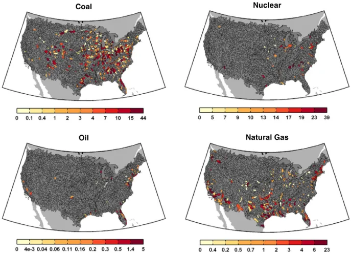
In order to project the effect of climate change on thermal power generation, we link a database of thermal power facilities (EW3 database from the Union of Concerned Scientists (UCS, 2012)) to the 8-digit HUC resolution. Annual Generation by the four major fuel types modeled is shown in Figure 2.
Coal Nuclear
Oil Natural Gas
12
Environmental policies regulating power plant withdrawals and releases vary state to state. For this study, we apply commonly used regulation types: withdrawal, near-field temperature, and far-field temperature. Withdrawal refers to a limit on the fraction of the flow that can be withdrawn from the river. The near-field temperature refers to the temperature of water near the release, before sufficient mixing has occurred, and far-field temperature refers to the water temperature further downstream of the release, after the effluent has been fully mixed. We use conservative regulations as follows: withdrawal is limited to less than ½ of the flow; near field temperatures are to not exceed 5.6°C warmer than the original water temperature after ½ of the of the river has mixed; and far-field temperatures are to not exceed 32°C.
In order to apply these regulations, we first need to estimate the water demands of the power plant. For once-through cooling plants, the procedure is straightforward. We can calculate the heat rejection in cooling water (HEAT), when the plant is running at capacity, as
𝐻𝐸𝐴𝑇 =𝐶𝑃(1−𝐸−𝛿)/𝐸 (18)
where HEAT is measured in kJ/s, CP is the total power plant capacity in kW, E is the thermal efficiency, and 𝛿 is the portion of heat lost to in-plant and stack losses (Adams and Harleman, 1979). We assume that thermal efficiency and in-plant and stack losses are constant and refer to values in EPRI (2002).
The amount of flow needed to remove this heat is
𝑄!"#$%! = ! !"#$
! ! (!!"#!!) (19)
where Tout is the effluent temperature and T is the water temperature in the river before the
effluent release. We assume that the temperature coming out of the plant is 11.2°C warmer than the water going into the plant, thus the difference between Tout and T is 11.2. We can then
calculate near-field and far-field temperatures at each hour and determine the amount of water the power plant can withdraw without violating the regulation.
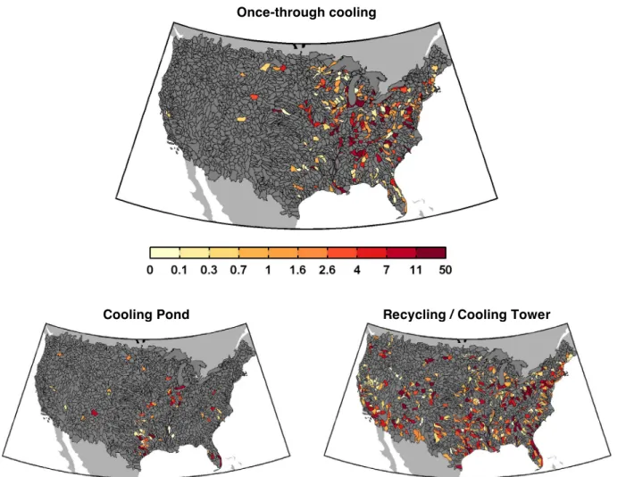
Thermal power plants with cooling towers and cooling ponds also withdraw water to make up for evaporation and to avoid the buildup of salts and solids. Estimating these withdrawals is more complicated. For this reason, we use values of withdrawal per MWh generated as reported in EPRI (2002). With these rates, we can estimate the power plant demand and apply our withdrawal regulation. Figure 3 shows the total annual generation for each HUC by cooling technology.
Finally, we calculate the fraction of regulated withdrawal over demands for each power plant. This fraction is used as an indicator of the climate change impacts. Note that, for once-through cooling plants this fraction implicitly assumes the plants prefer to generate at full capacity over the year. In reality, this is not the case due mostly to varying electricity demand and price, as well as grid system management; capacity factors for once-through plants have a calculated median of 0.55, with the majority of the plants ranging from 0.26 to 0.69 (the 25th and 75th
percentiles, respectively). Nonetheless, the allowable withdrawal fraction is an accurate indicator of the time during the year when the plant will not violate environmental regulations, a value that will likely impact generation if this fraction either increases or decreases in the future. One can
13
Once-through cooling
Cooling Pond Recycling / Cooling Tower
Figure 3. Total annual generation (in TWh) for three cooling technologies: once-through cooling, cooling
pond, and recycling.
also view this value as a measure of changes in availability; i.e. if the fraction decreases, the plant is more likely to have restricted withdrawal when the plant is needed to generate electricity (as dispatched by a grid operator), thus requiring a more expensive alternative plant to generate the needed electricity.
3. MODEL VALIDATION
USGS provides river temperature output for multiple river stations throughout the U.S. This river temperature dataset is used to validate the model. The model is first validated and calibrated for a detailed river reach with measured USGS hourly flow and temperature. We use the Delaware River for this, where the standalone river temperature model is used. The model is next evaluated at 16 stations with sufficient daily temperature data, where the full model system is used, the same framework used to later evaluate the climate change effects and GHG mitigation benefits.
14 3.1 The Delaware River
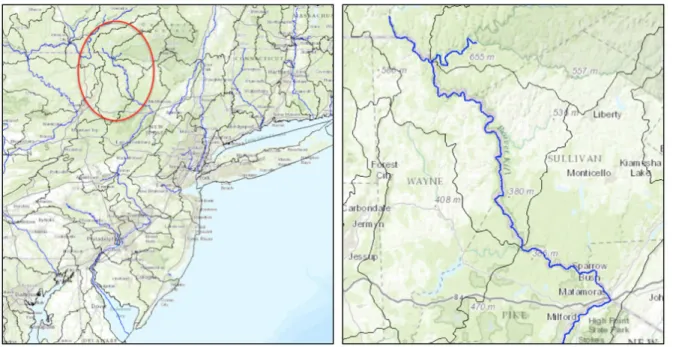
We validate the physical model of the rivers’ heat transfer by testing the model against a detailed flow model of the Delaware River. We choose a 190km reach of the Delaware that has well measured temperature and flow data, and no dams upstream. The section of the river that we use to test the model is shown in Figure 4.
We use Princeton atmospheric data, and the USGS Delaware River hourly upstream flow data from 2008 to force localized climate conditions and upstream flow and temperature conditions. We apply an upstream river temperature boundary condition based on air temperatures and Stefan-Preud’homme Constants, and apply the Princeton atmospheric data for wind, humidity, and pressure. Running the model we obtain river temperatures at the downstream portion of the river segment and compare them with measured temperatures. The results are presented in Figure 5.
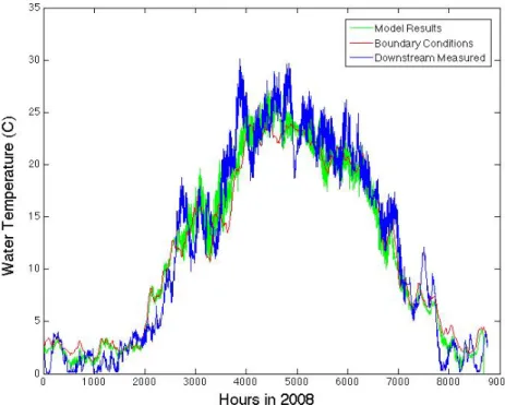
Since the summer months (June, July and August) are of critical importance for power plant operations, we show the model results for summer months in Figure 6. We end up with an R2of 0.8764 for hourly measurements and an R2of 0.89 for daily measurements.
Figure 4. The left map is of the Delaware River and coastline. The right map includes the entire section of
15
Figure 5. Hourly water temperature results for upstream boundary temperatures using
Stefan-Preud’homme Constants (red), downstream modeled temperatures (green) and measured downstream temperatures (blue).
Figure 6. Summer water temperature modeling results of downstream measured temperatures (blue),
modeled temperatures (green) and upstream boundary temperatures using Stefan-Preud’homme Constants (red).
16 3.2 Multi-HUC Model Testing
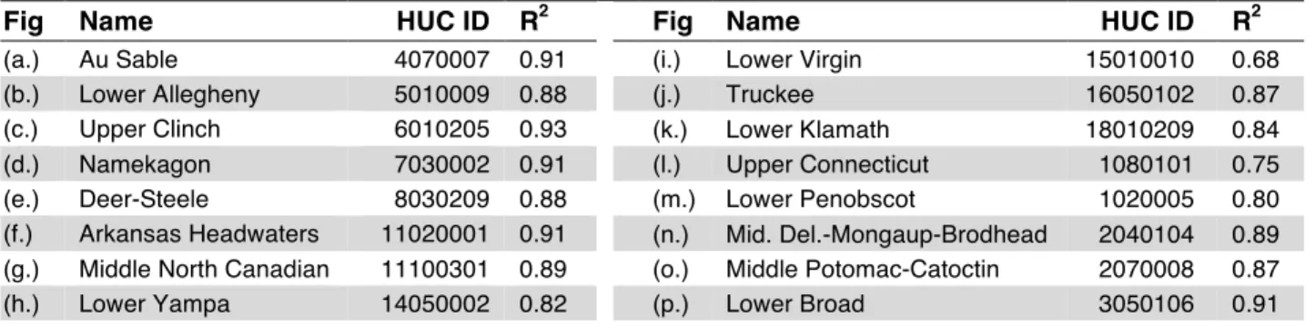
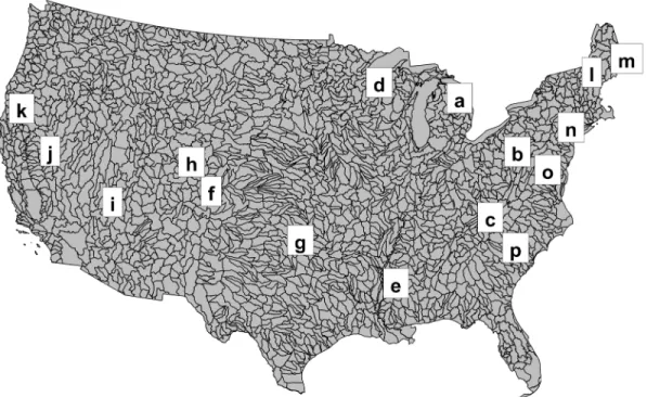
We select 17 HUCs with hourly station temperature data for the whole of 2008 and compare our model results with the measured temperatures. In this case, we use flow outputs from the water resource management model described previously, which outputs managed streamflow. Figure 7 shows the results for these HUCs. Statistics and information about these stations are shown in Table 1 and the locations are shown in Figure 8. These locations represent a variety of locations throughout the U.S., as well as a variety of flows and hydrologic reach orders. R2 values range from 0.68 to 0.93, with a median of 0.88. Given that these river temperatures were estimated at the back end of a number of models (climate, runoff, water demands, water
management), all contributing uncertainty and error, we find that the model performs with reasonable accuracy.
Figure 7. Observed (blue) and modeled (red) daily river temperatures for the 16 locations used.
Table 1. Validation information.
Fig Name HUC ID R2 Fig Name HUC ID R2
(a.) Au Sable 4070007 0.91 (i.) Lower Virgin 15010010 0.68
(b.) Lower Allegheny 5010009 0.88 (j.) Truckee 16050102 0.87
(c.) Upper Clinch 6010205 0.93 (k.) Lower Klamath 18010209 0.84
(d.) Namekagon 7030002 0.91 (l.) Upper Connecticut 1080101 0.75
(e.) Deer-Steele 8030209 0.88 (m.) Lower Penobscot 1020005 0.80
(f.) Arkansas Headwaters 11020001 0.91 (n.) Mid. Del.-Mongaup-Brodhead 2040104 0.89
(g.) Middle North Canadian 11100301 0.89 (o.) Middle Potomac-Catoctin 2070008 0.87
17
Figure 8. Locations of the river temperatures used for validation.
4. RESULTS
In this section, the results from the various scenarios are presented using three major indicators of climate change impacts: surface water availability, water temperature, and the fraction of time during the year that existing thermal power plants exceed river temperature regulations on uptake and release. The baseline is shown first for these indicators followed by the changes from the baseline, and we conclude with the mitigation benefits.
4.1 Baseline
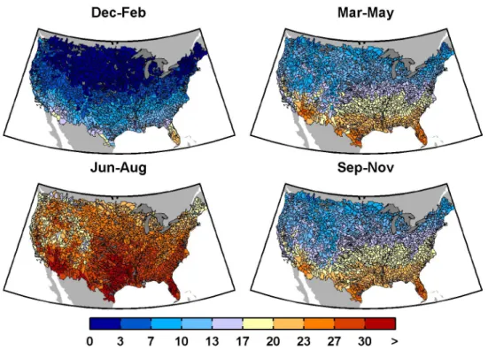
Baseline water temperature for four seasons of the year is shown in Figure 9 for the baseline median climate year. In the Dec-Jan season, mean water temperatures are close to 0°C for much of northern CONUS, with warmer temperatures in the south, especially in southern Florida where mean water temperature exceeds 20°C. The Jun-Aug season is considerably warmer, with most of the north and high-elevated regions exceeding 20°C, and the southern regions exceeding 30°C. Figure 10 shows the seasonal mean flow for the baseline median climate year. In this figure, we see somewhat consistent flow patterns across seasons, although there are a few regions that are season dependent, e.g. flows in the northwest are higher in Mar-May than Jun-Aug.
In order to summarize the power uptake restrictions caused by the environmental regulations imposed, we show the percentage of power plants as well as the total generation that falls into one of two categories: (i) no power plant restriction or (ii) withdrawal restriction (Table 2). As shown, power plants with once-through cooling technologies are most often restricted, with only 58% of the plants having no restrictions in the baseline scenario. While plants with cooling
18
Figure 9. Mean seasonal baseline surface water temperatures at the HUC-8 scale (°C).
19
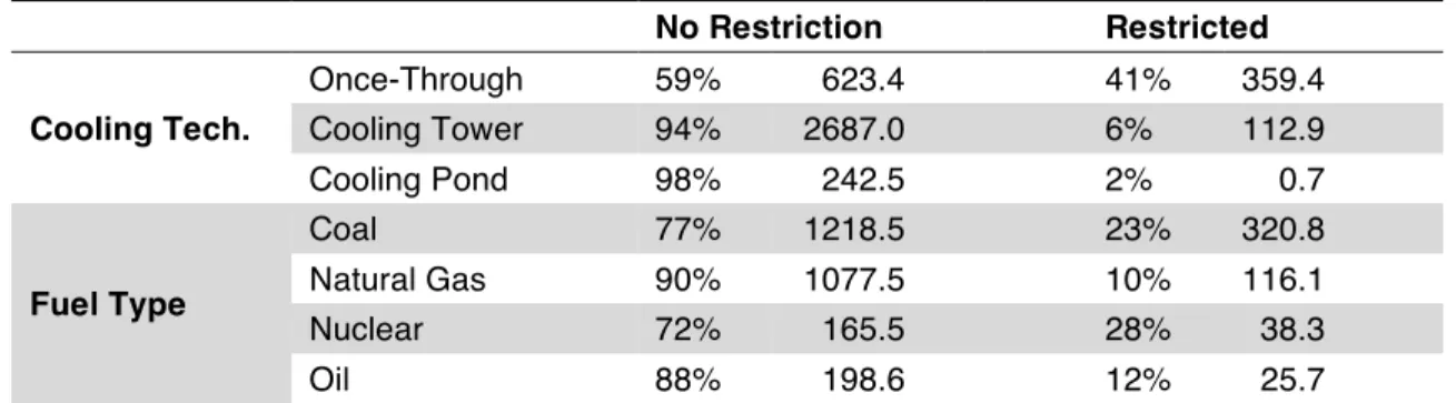
Table 2. Percentage of power plants and total generation (in TWh) in two categories based whether or
not the power plant is restricted by the environmental regulations imposed.
No Restriction Restricted Cooling Tech. Once-Through 59% 623.4 41% 359.4 Cooling Tower 94% 2687.0 6% 112.9 Cooling Pond 98% 242.5 2% 0.7 Fuel Type Coal 77% 1218.5 23% 320.8 Natural Gas 90% 1077.5 10% 116.1 Nuclear 72% 165.5 28% 38.3 Oil 88% 198.6 12% 25.7
towers make up the majority of annual electricity generation, they are less likely to be restricted because they require less withdrawal for cooling. Also, note that we will not see improvements in the future for plants that do not have restrictions in the baseline since the allowable withdrawal fraction is already at the maximum—one. This means that once-through cooling plants have more capacity for future increases in the allowable withdrawal fraction than do plants with cooling towers. In terms of the fuel type, nuclear plants are most likely to be restricted, followed by coal plants; however, the restricted coal plants represent a larger portion of annual generation than nuclear.
4.2 Future Changes
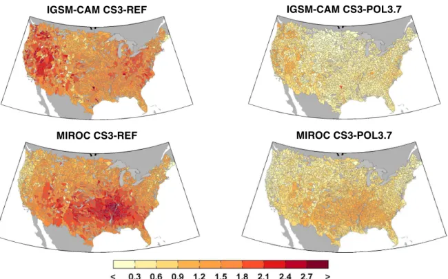
Now we look specifically at changes in water temperature, flow, and withdrawal restriction for CONUS. For these, we display the differences in the results, comparing the various emissions scenarios to the control scenario (no changes in climate) to measure the climate change impact. Figure 11 shows the changes in water temperature by 2050 for two policy cases—CS3-REF and
CS3-POL3.7—as well as the two GCMs—IGSM-CAM and MIROC. As shown, water
temperature varies by magnitude and geographic location. CS3-REF is always warmer than the stringent mitigation case, CS3-POL3.7, though the variation across HUCs is driven more by GCM than mitigation policy—IGSM-CAM shows larger increases in temperature in the west, while MIROC shows larger increases in temperature in the Great Plains. These changes in water temperature are influenced by changes in climate as well as changes in flow.
Figure 12 shows the projections of changes in streamflow in 2050 for the same four
scenarios. We see that the IGSM-CAM results in considerably higher streamflow than MIROC, and again the geographic variation is driven more by GCM than by mitigation policy. In fact, the differences between mitigation policies are different in sign for the two GCMs: compared to
CS3-REF, MIROC mostly results in streamflow increases for CS3-POL3.7, whereas
IGSM-CAM mostly results in streamflow decreases.
These changes in water temperature and streamflow then influence the allowable uptake for thermal power plants, as implemented in the power plant model described previously. Changes in allowable withdrawal for 2050 are shown for the same four scenarios, again as the change
20
IGSM-CAM CS3-REF IGSM-CAM CS3-POL3.7
MIROC CS3-REF MIROC CS3-POL3.7
Figure 11. Change in Temperature (°C) from the control scenario in 2050.
IGSM-CAM CS3-REF IGSM-CAM CS3-POL3.7
MIROC CS3-REF MIROC CS3-POL3.7
21
IGSM-CAM CS3-REF IGSM-CAM CS3-POL3.7
MIROC CS3-REF MIROC CS3-POL3.7
Figure 13. Changes in withdrawal allowed for HUCs with once-through cooling technology in 2050.
IGSM-CAM CS3-REF IGSM-CAM CS3-POL3.7
MIROC CS3-REF MIROC CS3-POL3.7
22
from the control scenario for once-through cooling plants in Figure 13 and for plants with cooling towers in Figure 14. As expected, once-through cooling plants are more sensitive to changes in climate than plants with cooling towers. Also, note that the GCM projections of changes in flow play a major role in these values. There are less once-through cooling plants in the west where water is more scarce. Since IGSM-CAM is projecting a hotter and drier climate in the west, and a relatively cooler and wetter climate in the east, once-through cooling plants conditions improve in the future. MIROC projects a drier and considerably hotter climate in the east and mid-west, causing a substantial decrease in allowable withdrawal for once-through cooling plants.
In Figure 15, we show the total changes in allowable withdrawal for all cooling technologies, future scenarios, and separate out the dry, median, and wet climate years. Note that the total generation from the plants considered is over 3,200 TWh annually. Using national energy prices ($90/MWh, in 2005 USD), 1% of this total energy is equivalent to about 3 trillion USD/year. In these bar plots, we can see a clear difference between the results from IGSM-CAM and MIROC, showing that differences in GCM model structure play a major role in the outcome. In fact, comparing CS3-REF to CS3-POL3.7 in 2100, we see that IGSM-CAM projects negative effects from GHG mitigation, while MIROC projects positive effects, although the positive effects projected by MIROC are considerably larger than the negative effects from IGSM-CAM. Since the summer is the most likely season for negative impacts to occur, we show summer changes in
IGSM-CAM CS3-REF IGSM-CAM CS3-POL4.5 IGSM-CAM CS3-POL3.7
MIROC CS3-REF IGSM-CAM CS3-POL4.5 MIROC CS3-POL3.7
Figure 15. Percent change in total withdrawal allowed weighted by annual generation, where positive is
23
allowable withdrawal in Table 3 for IGSM-CAM and Table 4 for MIROC. The changes projected by IGSM-CAM for the summer are mild—a result of increased flows and increased temperatures having opposite effects on the allowable withdrawal fraction. For once-through cooling, where we see the largest climate change effect, there is a GHG mitigation benefit of
POL3.7 of about 1.3% in CS3 and 1.7% in CS6, while CS3-POL4.5 has no benefit. By fuel type,
oil benefits the most, although oil accounts for the least annual electricity generation. Coal plants also benefit from POL3.7 as compared to the reference, with a benefit of 1.2% for both CS3 and
CS6. For the MIROC results, allowable withdrawal decreases in the summer for all scenarios and power generation types. Again, once-through cooling benefits the most from Policy 3.7
mitigation, by 2.3% for CS3 and 2.9% for CS6.
Table 3. IGSM-CAM – Climate change impact on allowable withdrawal in the summer (Jun-Aug) in 2050
for the median-climate year, where positive is an increase in allowable withdrawal and negative is a decrease.
IGSM-CAM CS3-REF CS3-pol4.5 CS3-pol3.7 CS6-REF CS6-pol3.7
Cooling Tech. Once-Through -0.8% -0.9% 2.1% 3.4% 5.1% Cooling Tower 0.4% -0.5% 0.5% -0.3% 1.5% Cooling Pond 0.0% -0.3% 0.0% -0.2% 0.0% Fuel Type Coal -0.3% -0.9% 0.9% 1.1% 2.3% Natural Gas -0.1% 0.0% 0.1% -0.1% 1.9% Nuclear 0.1% -0.3% 1.0% 1.4% 3.4% Other Fossil -1.3% -1.1% 1.4% -4.7% -2.0%
Table 4. MIROC – Climate change impact on allowable withdrawal in the summer (Jun-Aug) in 2050 for
the median-climate year, where positive is an increase in allowable withdrawal and negative is a decrease.
MIROC CS3-REF CS3-pol4.5 CS3-pol3.7 CS6-REF CS6-pol3.7
Cooling Tech. Once-Through -6.0% -4.1% -3.7% -8.3% -5.5% Cooling Tower -1.8% -1.1% -1.0% -2.2% -1.5% Cooling Pond -0.8% -0.2% -0.1% -0.4% -0.7% Fuel Type Coal -4.1% -2.6% -2.4% -5.2% -3.6% Natural Gas -0.7% -0.4% -0.4% -1.0% -0.5% Nuclear -1.8% -1.2% -1.2% -2.5% -1.6% Other Fossil -2.5% -1.8% -1.1% -3.1% -2.1%
4.3 Valuation of Mitigation Benefits
Projections of power prices from ReEDS are used to value the change in thermal generation (see McFarland et al., forthcoming). Scenarios modeling reductions in GHG emissions assume that supply-side costs in the electric sector associated with shifting the generation mix are incorporated into the price of electricity. We consider two illustrative electricity price scenarios that include and exclude the marginal cost of CO2. Electricity prices inclusive of CO2 emission costs show higher prices under the mitigation scenarios (e.g., prices in 2050 range from
24
$115/MWh in the REF scenario to $127/MWh in the POL3.7 scenario in 2005$), whereas excluding emissions costs, prices are relatively similar across scenarios (e.g., 2050 prices are $115/MWh in REF versus $117/MWh in the POL3.7 scenario). These two price scenarios produce high- and low-end estimates, respectively, of the benefits of global GHG mitigation on U.S. thermal generation. The high price scenario, inclusive of emission costs, would best reflect the lost value of generation from low-emitting thermal units such nuclear or a fossil technology with carbon capture and storage. The low price scenario, exclusive of emission costs, would reflect the lost value of generation from coal, gas, or oil units without carbon capture. Note that these results do not consider feedbacks between thermal production, prices, and production from other sources—to fully capture the economic effects of changes in thermal power generation potential, we would iterate our model with an electricity sector-planning model such as ReEDS.
Table 5 shows these results for the three emission scenarios under CS values of 3°C and/or 6°C for IGSM-CAM, and Table 6 shows these results for MIROC. In 2050, under the price scenario including emissions costs, the annual benefits of reducing GHG emissions under the
CS3-POL3.7 scenario are approximately $35 billion for IGSM-CAM and $36 billion for
MIROC. Excluding emissions costs, the benefits are approximately $8.3 billion for IGSM-CAM and $39 million for MIROC. The 2015 to 2050 present value benefits under these two price scenarios for the POL3.7 scenario, discounted at 3%, are approximately $536 billion and $53 billion, respectively, for IGSM-CAM, and $538 billion and $65 billion, respectively, for MIROC. The high-end estimate reflects the value of lost generation from no- or low-emitting thermal technologies while the low-end estimate reflects the value of emitting technologies. The actual benefit would reside somewhere in between and depend upon the transition pathway from emitting to non-emitting generation sources.
Table 5. IGSM-CAM – National average change in thermal power revenues (millions of 2005$) from
control in 2025 and 2050 under each of the ReEDS price scenarios.
Price Scenario Year CS3-REF CS3-POL4.5 CS3-POL3.7 CS6-REF CS6-POL3.7
Emission costs included 2025 $2,092 $12,760 $25,438 $2,687 $27,787 2050 $3,807 $15,855 $38,879 $7,085 $42,097 Emission costs excluded 2025 $2,092 $2,647 $3,995 $2,687 $6,171 2050 $3,807 $5,532 $8,268 $7,085 $11,210
Table 6. MIROC – National average change in thermal power revenues (millions of 2005$) from control in
2025 and 2050 under each of the ReEDS price scenarios.
Price Scenario Year CS3-REF CS3-POL4.5 CS3-POL3.7 CS6-REF CS6-POL3.7
Emission costs included 2025 ($2,154) $9,999 $21,059 ($3,035) $20,539 2050 ($5,888) $10,130 $29,881 ($8,090) $28,095 Emission costs excluded 2025 ($2,154) ($12) ($60) ($3,035) ($542) 2050 ($5,888) ($17) $39 ($8,090) ($1,594)
25 5. CONCLUSION
We build and validate a standalone river temperature model and apply this generic model to the United States at the 8-digit HUC scale. We demonstrate that the standalone model performs well with a detailed description of flow and geometry. Next, we construct a series of models that represent the system at hand. A rainfall-runoff model is used to convert climate from GCM projections to changes in runoff. In parallel, a water demand model is implemented to develop water demand projections for the various scenarios. Next, a water resource planning model is used to simulate water allocation and management at the HUC-8 scale. The standalone water temperature model is applied to the streamflow and climate output to estimate surface-water temperatures. Finally, we compare regulated withdrawal to demands for withdrawal from thermal power plants in CONUS, and estimate the power generation impact of climate change (represented by changes in allowable withdrawal). We demonstrate that this modeling system performs reasonably well for a generalized 8-digit HUC river for 16 stations of daily water temperature across the United States.
After developing a number of future scenarios with information from two GCMs, two climate sensitivities, and three mitigation policies, we run the system of models for four eras and three climate years: wet, median, and dry. We find that water temperatures increase by 2050 to 1–2°C in the CS3-REF case and 0.3–1°C in CS3-POL3.7. Temperatures in 2100 do not significantly increase for the stringent GHG mitigation case, CS3-POL3.7, while temperatures in CS3-REF
increase by about 4–6°C annually. Thus, there is a strong incentive to mitigate GHG emissions in order to keep surface water temperatures at reasonable levels. We find that the two GCMs
project drastically different patterns of surface water warming—IGSM-CAM projects warming to be more severe in the west, while MIROC projects more warming in the east and the Great Plains. These differences in geographic patterns between the GCMs are partially attributed to the patterns of changes in precipitation, which manifest to changes in streamflow across CONUS— where IGSM-CAM projects substantial increases in streamflow in the majority of the region, and MIROC projects substantial decreases.
These different geographic patterns in climate change projections for the two GCMs result in significant differences in thermal power plant impacts. IGSM-CAM generally projects increases in allowable withdrawal, and the most extreme scenarios—namely, CS6-REF—show the greatest benefit to thermal power generation, which rises above 5% annually in 2050. The MIROC projections provide a different picture of the future of thermal power generation, with substantial reductions in potential generation of about 5% at most in 2050, rising to more than 10% in 2100. We then take a more in-depth look into the impacts on the Jun-Aug season. We find that the hotter temperatures in the summer counterbalance most of the increases in runoff from IGSM-CAM, resulting in smaller changes to allowable withdrawal. For MIROC, we find that negative impacts in the summer are also greater, with reductions in allowable withdrawals reaching 6% for CS3-REF—much larger than the 0.8% for IGSM-CAM. In spite of the differences, the mitigation benefit of POL3.7 for the two GCMs is surprisingly close for the summer, at about 1.3% for IGSM-CAM and 2.3% for MIROC.
26
With the striking differences between the two GCMs used in this analysis, an obvious improvement would be to run the series of models with more GCMs. We believe that these two GCMs represent both a wet climate projection and a dry climate projection, but are not certain if these two GCMs represent extremes in terms of allowable withdrawal or water temperature changes. While adding more GCMs would provide additional points on the uncertainty distribution, we would still only provide the range of points, of which the probabilities are unknown. Another solution would be to analyze this system of models with an ensemble of scenarios similar to Webster et al. (2011) and Schlosser et al. (2012).
In addition to addressing the issue of climate projection uncertainty, the models used in this analysis also contribute uncertainty in input data, assumptions, and model structure. One way to address this uncertainty is to reduce the spatial or temporal scale of the models. We can also replace or improve the various assumptions—e.g., the assumption of a parabolic river
cross-sectional shape for all rivers in CONUS, which might be improved by altering the shape by topography or region. Another potential area of improvement is the detail at which we address power plant withdrawal demand and uptake. We assume a consistent change in the temperature of water released by once-through cooling plants. This heat would likely vary by plant and by capacity factor. Furthermore, water management and power plant facilities are changing over time, both long-term changes (i.e. investments in new facilities and retiring older ones) as well as short-term variations, which respond to changes in food and electricity prices, all of which vary throughout each year, week and day. Future research plans are already in place to address many of these assumptions.
Nevertheless, this study does provide a necessary step to understanding the impacts of climate change on both water temperature and thermal power plant generation.
6. REFERENCES
Adams, E.E., and R.F. Harleman, 1979: Waste heat management in the electric power industry: issues of energy conservation and station operation under environmental constraints. Energy Laboratory Report No. MIT-EL 79-040.
Allen, R.G., L.S. Pereira, D. Raes, and M. Smith, 1998: Crop evapotranspiration—guidelines for computing crop water requirements. FAO Irrigation and Drainage, paper 56.
Brown, L.C. and T.O. Barnwell, 1987: The enhanced stream water quality models QUAL2E and QUAL2E-UNCAS: documentation and user manual. US Environmental Protection Agency, Office of Research and Development, Environmental Research Laboratory.
Brungs, W.A., B.R. Jones and D.I. Mount, 1977: Temperature criteria for freshwater fish. Protocol and Procedures. Environmental Research Laboratory-Duluth.US EPA, Citeseer.
Chandel, M.K., L.F. Pratson and R.B. Jackson, 2011: The potential impacts of climate-change policy on freshwater use in thermoelectric power generation. Energy Policy 39(10): 6234– 6242.
Chapra, S.C., 1997: Surface Water-Quality Modeling. McGraw-Hill, New York.
Chapra, S.C., 2008: Surface water-quality modeling. Waveland Press. DOE, December 2006: Energy Demands on Water Resources: Report to Congress on the Interdependency of Energy and Water. White Paper. Corps [U.S. Army Corps of Engineers], 2013: National Inventory of Dams. accessed June 15, 2013 at
27
Droogers, P., and R. Allen, 2002: Estimating reference evapotranspiration under inaccurate data conditions.
Irrigation and Drainage Syst. 16, 33–45
EIA [Energy Information Administration], 2013: Annual Energy Outlook.
EPRI [Electric Power Research Institute], 2002: Water & Sustainability (Volume 3): U.S. Water Consumption for Power Production—The Next Half Century. EPRI, Palo Alto, CA. 1006786.
Farmer, W.H. and R.M. Vogel, 2012: Performance-weighted methods for estimating monthly streamflow at ungagged sites. Journal of Hydrology 477, 240-250.
Förster, H. and J. Lilliestam, 2010: Modeling thermoelectric power generation in view of climate change.
Regional Environmental Change 10(4): 327–338.
Gooseff, M.N., K. Strzepek and S.C. Chapra, 2005: Modeling the potential effects of climate change on water temperature downstream of a shallow reservoir, Lower Madison River, MT. Climatic Change 68(3): 331– 353.
Graham, J., 1949: Some effects of temperature and oxygen pressure on the metabolism and activity of the speckled trout, Salvelinus fontinalis. Canadian Journal of Research 27(5): 270– 288.
Gupta V. and S. Sorooshian, 1985: The relationship between data and the precision of parameter estimates of hydrologic models. J. Hydrol. 81, 57–77.
Herb, W. and H. Stefan, 2010: Projecting the impact of climate change on coldwater stream temperatures in Minnesota using equilibrium temperature models. Project Report.
IPCC [International Panel on Climate Change], 2014: International Panel on Climate Change 5th Assessment Report.
Kaczmarek, Z., 1993: Water balance model for climate impact analysis. ACTA Geophysica Polonica 41(4):1–16. Kenny, J.F., N.L. Barber, S.H. Susan, K.S. Linsey, J.K. Lovelace and M. Maupin, 2014: Estimated Use of
Water in the United States in 2005. United States Geological Survey, Circular 1344.
Kenny, J.F., N.L. Barber, S.S. Hutson, K.S. Linsey, J.K. Lovelace, and M.A. Maupin, 2009: Estimated use of water in the United States in 2005. U.S. Geological Survey Circular 1344, 52 p.
Leopold, L.B. and T. Maddock, 1953: The hydraulic geometry channels and some physiographic implications. Geological Survey Professional Paper 252, Washington, D.C.
MacCormack, R.W., 1969: The effect of viscosity in hypervelocity impact cratering. Am. Inst. Aeronaut. Astronaut Paper 69, 354.
MacLeod, J. and E. Pessah, 1973: Temperature effects on mercury accumulation, toxicity, and metabolic rate in rainbow trout (Salmo gairdneri). Journal of the Fisheries Board of Canada 30(4): 485–492.
Monier, E., J.R. Scott, A.P. Sokolov, C.E. Forest and C.A. Schlosser, 2013: An integrated assessment modeling framework for uncertainty studies in global and regional climate change: the MIT IGSM-CAM (version 1.0).
Geosci. Model Dev. 6, 2063–2085, doi: 10.5194/gmd-6-2063-2013.
Monier, E., X. Gao, J. Scott, A. Sokolov and A. Schlosser, 2014: A framework for modeling uncertainty in regional climate change. Climatic Change, doi: 10.1007/s10584-014-1112-5.
Ngo-Duc, T., T. Oki and S. Kanae, 2007: A variable streamflow velocity method for global river routing model: model description and preliminary results. Hydrology & Earth System Sciences Discussions 4(6).
Olivera, F., J. Famiglietti and K. Asante, 2000: Global-scale flow routing using a source-to-sink algorithm.
Water Resources Research 36(8): 2197–2207.
Paltsev, S., E. Monier, J. Scott, A. Sokolov and J. Reilly, 2013: Integrated economic and climate projections for impact assessment. Climatic Change, doi: 10.1007/s10584-013-0892-3.
28
Sheffield, J., G. Goteti and E.F. Wood, 2006: Development of a 50-year high-resolution global dataset of meteorological forcings for land surface modeling. J. Climate 19: 3088–3111.
Schlosser, C.A., X. Gao, K. Strzepek, A. Sokolov, C.E. Forest, S. Awadalla and W. Farmer, 2012: Quantifying the likelihood of regional climate change: A hybridized approach. Journal of Climate 26(10): 3394–3414, doi: 10.1175/JCLI-D-11-00730.1.
Sieber, J., and D. Purkey, 2007: User Guide for WEAP21. Stockholm Environment Institute.
Short, W., P. Sullivan, T. Mai, M. Mowers, C. Uriarte and N. Blair, 2011: Regional Energy Deployment System (ReEDS). Contract, 303, 275–3000.
Snodgrass, W.J., 1974: A predictive phosphorus model for lakes: development and testing. Ph.D. Dissertation, University of North Carolina, Chapel Hill, NC.
Stefan, H.G. and E.B. Preud’homme, 1993: Stream Temperature Estimation From Air Temperature. Water Resources Bulletin 29(1): 27–45.
Strzepek, K., A. McCluskey, B. Boehlert, M. Jacobsen and C. Fant, 2011: Climate variability and change: a basin scale indicator approach to understanding the risk to water resources development and management.
Water papers, Washington, D.C.: World Bank
( http://documents.worldbank.org/curated/en/2011/09/15897484/climate-variability-change-basin-scale-indicator-approach-understanding-risk-water-resources-development-management).
Strzepek, K., M. Jacobsen, B. Boehlert and J. Neumann, 2013: Toward evaluating the effect of climate change on investments in the water resources sector: insights from the forecast and analysis of hydrological indicators in developing countries. Environmental Research Letters 8(4):044014.
UCS [Union of Concerned Scientists], 2012: UCS EW3 Energy-Water Database V.1.3.
http://www.ucsusa.org/ew3database.
USDA [U.S. Department of Agriculture], 2010: Farm and ranch irrigation survey (2008): Volume 3, Special Studies, Part 1, AC-07-SS-1.
USFS [U.S. Forest Service], 2014: Water Supply Stress Index (WaSSI). accessed on September 20, 2014 at
http://www.forestthreats.org/research/tools/WaSSI.
USWRC [U.S. Water Resources Council], 1978: The Nations’ Water Resources 1975-2000. Second National Water Assessment (http://water.usgs.gov/watercensus/nwr-1975-2000.html).
van Vliet, M., J. Yearsley, W. Franssen, F. Ludwig, I. Haddeland, D. Lettenmaier and P. Kabat, 2012a: Coupled daily streamflow and water temperature modelling in large river basins. Hydrology & Earth System Sciences Discussions 9(7).
van Vliet, M.T., J.R. Yearsley, F. Ludwig, S. Vögele, D.P. Lettenmaier and P. Kabat, 2012b: Vulnerability of US and European electricity supply to climate change. Nature Climate Change 2(9): 676–681.
Waldhoff, S., J. Martinich, M. Sarofim, B. DeAngelo, J. McFarland, L. Jantarasami, K. Shouse, A. Crimmins and J. Li, 2014: Overview of the special issue: A multi-model framework to achieve consistent evaluation of climate change impacts in the United States. Climatic Change, doi: 10.1007/s10584-014-1206-0.
Walker, J. and J. Lawson, 1993: Natural Stream Temperature Variations in a Catchment. Water Research 11(1): 27–45.
Webster, M., A.P. Sokolov, J.M. Reilly, C.E. Forest, S. Paltsev, C.A. Schlosser, C. Wang, D. Kicklighter, M. Sarofim, J. Melillo, R.G. Prinn and H.D. Jacoby, 2011: Analysis of climate policy targets under uncertainty.
Climatic Change 112(3-4), 569-583.
Yearsley, J., 2012: A grid-based approach for simulating stream temperature. Water Resources Research 48(3). Yearsley, J.R., 2009: A semi-Lagrangian water temperature model for advection-dominated river systems.