A formal support to business and architectural
design for service-oriented systems
Roberto Bruni1, Howard Foster2, Alberto Lluch Lafuente3, Ugo Montanari1, and Emilio Tuosto4
1
Department of Computer Science, University of Pisa, Italy 2
Imperial College London, UK
3 IMT Institute for Advanced Studies Lucca, Italy 4
Department of Computer Science, University of Leicester, UK
Abstract. Architectural Design Rewriting (ADR) is an approach for the design of software architectures developed withinSensoriaby reconciling graph transformation and process calculi techniques. The key feature that makes ADR a suitable and expressive framework is the algebraic handling of structured graphs, which improves the support for specification, analysis and verification of service-oriented architectures and applications. We show how ADR is used as a formal ground for high-level modelling languages and approaches developed withinSensoria.
1
Introduction
The IST-FET Integrated ProjectSensoriaaims at developing a comprehensive approach to the engineering of service-oriented software systems where foun-dational theories, techniques and methods are fully integrated into pragmatic software engineering processes. The development of mathematical foundations and mathematically well-founded engineering techniques for service-oriented computing constitutes a key research activity of Sensoria.
In this paper we report the outcome of some research efforts within Sen-soriaaimed at developing formalisations of high-level modelling languages for service-oriented systems. More precisely, we present Architectural Design Rewrit-ing (ADR) [5] and we explain how ADR can be used as a formal model for architectural and business design and how it helps in formalising crucial aspects of the UML4SOA [10] and SRML(cf. [9]) modelling languages, as well as the software modes approach [11].
ADR has been inspired by the long-term experience of Sensoriaresearchers on Graph Transformation Systems, process calculi and software engineering and has been entirely developed under theSensoriaproject, allowing us to establish interesting links with many other formalisms developed withinSensoriaand making it possible to strengthen the collaboration among different research groups with different expertise within the project.
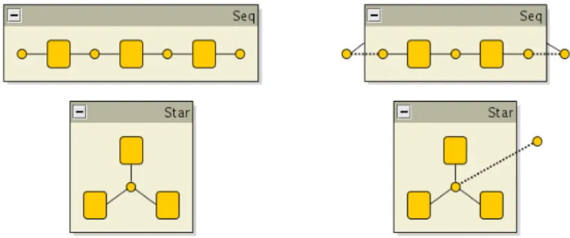
Fig. 1.“Graphs within boxes” (left) and “Graphs within edges” (right)
Synopsis. §2 explains the motivating principles of ADR.§3 introduces ADR basics and explains how ADR can be considered as an Architectural Description Language on the basis of a running example.§4 overviews some key aspects of ADR-based formalisations of UML4SOA, SRML and Sofware Modes.
2
Rationale behind Architectural Design Rewriting
The use of graphs or diagrams of various kinds is pervasive in Computer Science, as they are very handy for describing in a two-dimensional space the logical or topological structure of systems, models, states, behaviours, computations, etc.; the reader might be familiar, for example, with the classical graphical presentations of entity-relationship diagrams, of finite state automata and labelled transition systems, of data-structures (like various kinds of lists and trees), static and behavioural UML diagrams (like class, message sequence and state diagrams), of computational formalisms like Petri nets, and so on. One obvious advantage of using graphs or diagrams lies in their ability to represent in a direct way relevant topological features of the systems or models they describe.
On the one hand, software architectural models are intended to describe the structure of a system in terms of computational components, their interactions, and its composition patterns [14]. Usingplain hypergraphs, the above perspective can find its realisation by modelling “components” and “connectors” as hyperedges and their interconnecting “ports” as nodes. Moreover, nodes, hyperedges and their tentacles can be typed so to discard erroneously linked systems.
On the other hand, in [2] it is argued that structured graphs are the most ap-propriate ones for service-oriented and global computing systems, where scalable techniques and open-ended specifications are important issues not immediately met by plain hypergraphs alone. Structured graphs offer better support for “un-derstanding” graphs (like parsing and browsing large systems), designing systems (like expressing requirements and specifications, facilitating abstraction and re-finement, allowing modularity and seamless composition), supporting automated analysis and verification (like model construction, model conformance, behavioural
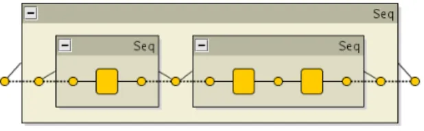
Fig. 2.“Nested graphs”
analysis, assessing sound reconfiguration and refactoring transformations) and last but not least, sound and complete visual encoding of computational systems.
Different kinds of structures can be super-imposed on graphs. The simplest one is enclosing a graphGin some sort of box whose labelB implicitly defines some properties of the enclosed graph, i.e., itsstyle. For example, Fig. 1 (left) shows some basic examples of “topologically” labelled graphs, that can be written, e.g., Seq[G] andStar[G0] (for obvious graphs G, G0 derivable from Fig. 1) or, equivalently, as membership annotationsG:Seq andG0:Star, whereSeq can be read as the set of all sequentially-linked graphs, and similarly forStar.
The natural extension of taking a “graphs within boxes” view is then the “graphs within edges” (or “nested graphs”) view, where boxing can be iterated by allowing style labels that are edges themselves (see Fig. 1 (right)). Note that the boxed interfaces are now equipped with tentacles and that dotted lines make explicit the correspondence between inner nodes exposed by interfaces and actual nodes where the module is linked to. When the nodes attached to the tentacles of its (outermost) interface are read as formal parameters, we call it adesign. This way, boxes can be read as enhanced interfaces allowing for more sophisticated forms of containment, strctured composition, modular specification, logical hierarchies, and node sharing, among others, making such features easily understandable also to non-specialists. For example, Fig. 2 shows that sequential composition of (nested) sequential graphs still yields a sequential graph. Note that if we remove all enclosing boxes from a nested graph then we are left with anunderlying plain graph, but we loose any information about the conceptual organization of its elements. Thus in a sense, nested graphs can be read as “blueprints” of their underlying graphs.
3
Design Foundations
This section overviews the principles ofArchitectural Design Rewriting (ADR) [5].
3.1 System Configurations
A system configuration in ADR is the underlying graph of a design, representing the architectural units and their interconnections. Recall that a graph is a tuple
G=hV, E, θiwhereV is the set of nodes,E is the set of edges andθ:E→V∗
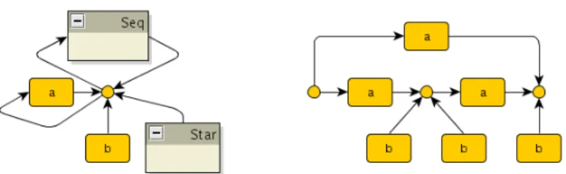
Fig. 3.A type graph (left) and a configuration (right)
is a pairhG, tG:G→Ti, whereGis theunderlying graph and tG:G→T is a graph morphism. From now on we assume that graphs are always typed over a suitable type graphT, even if sometimes it is not described explicitly. Intuitively, a type graph plays the role of an architectural vocabulary and enforces certain tentacles to be connected to nodes of a given type, but note that a type graphT
itself cannot impose any sophisticated topological structure on T-typed graphs. The distinction between refinable components and non-refinable components in software architectures amounts to the distinction between non-terminal and terminal edges in ADR. The underlying idea is the same: a non-terminal edge is an edge intended to be refined (i.e., replaced by an arbitrarily complex graph). Non-terminal edges can appear in designs, representing unspecified parts of a configuration (a refinable component) or in design productions (see later). Terminal edges instead represent parts of a graph that cannot be further refined (non-refinable components).
Fig. 3 shows a type graph (left) and a configuration typed over it (right), where the typing is made explicit by the shapes and labels of nodes and edges. Refinable components are represented as group-boxes, while non-refinable components as plain boxes. The type graph in Fig. 3 includes both kinds of edges, while the configuration isground, in the sense that it consists of terminal edges only.
3.2 Architectural Designs
An architectural design is a nested graph representing a structured system configuration. Technically, adesignis a triple d=hLd, Rd, idi, whereLdis the
interface graph consisting of a single non-terminal edge (the interface) whose tentacles are attached to distinct nodes;Rdis thebody graph; andid:VLd→VRd
is the (injective) function that maps interface nodes to body nodes.
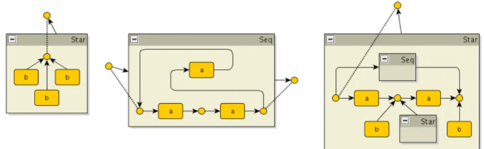
For example, Fig. 4 shows three designs: the design on the left has a ground body graph that matches the intuition of its interface edgeStar; the design on the center has a ground body graph shaped as a ring, hence not exactly matching the intended meaning associated with the interface edge Seq; the rightmost design has a body graph involving all different kinds of edges and exhibiting little correspondence with the intuitive meaning of its interface edgeStar.
Fig. 4.Three designs
3.3 Architectural Styles
To avoid the above raised problems, the shape of graphs embedded in a design must be constrained. To this aim architectures are designed inductively by a set of composition operators called design productions which enable: (i) top-down refinement, like replacing a refinable components with its (possibly non-ground) realisation, (ii) bottom-up typing, like inferring the “style” of a system configuration, and (iii) well-formed composition, like composing some well-typed architectures together so to guarantee that the result is still well-typed.
Design productions take inspiration from Graph Grammars [7], where hyper-edge replacement rules allow to substitute, in a graph G, a (refinable) edge L
with a particular graphR, suitably connected to the nodes ofGwhereL was connected to. Technically, a design productionp=hLp, Rp, ipiis very much like a design but with an order on the non-terminal edges{e1, ..., enp} appearing in
its body graph (intuitively, the order of the arguments they represent). Thetype of a productionpis A1×A2×. . .×Anp →Ap, whereAk is the non-terminal
symbol labelling thek-th non-terminal edgeek of the body of the production. The functional type means thatp can be considered as a function that when applied to a tuplehd1, d2, . . . , dnpiof designs such thatdi:Ai, returns a design d = p(d1, d2, . . . , dnp) of type Ap. The definition is obvious: d = (Lp, Rd, ip),
whereRd is obtained fromRp by replacing each non-terminal edgeek in it with
body graphRdk ofdk respecting its tentacle functionidk, fork= 1, . . . , np.
This view corresponds to a bottom-up design development: a design is con-structed by putting together some component designs. However, the dual view is also possible: a production can be seen as a refinement of an abstract component of typeAp as an assembly of concrete and abstract components, the latter being of typeA1, A2, . . . Anp.
For example, Fig. 5 shows simple design productions for configurations shaped as sequences (Seq) and stars (Star). Note that, according to the functional flavor described above, the labels of enclosing boxes are enriched with the information about the name of the production, the names of its “arguments”, their types and the type of the result. For example we have constant building blocksaandb
Fig. 5.Architectural styles for sequences and stars
X, Y of style Seq and returns a graph of style Seq obtained by concatenating the two ends ofX andY to form a sequence and exposing a suitable interface. Another possible reading for the rules is the following: a graph has styleSeq if it is either a single componentaor the sequential composition of two other graphs of stylesSeq; a graph has styleStar if it is a single component bor a sequence seen as a chord, or the joint composition of two other graphs of styles Star.
3.4 Design Algebra
One key feature of architectural styles is that design productions provide us with a signature for defining graphs. Furthermore, the terms over such a signature do not even need to mention node names or edge names, because the way in which components are connected is entirely embedded in each operation (i.e., in each design production). For example, a term likestar(b,chord(seq(seq(a, a), a))) describes a ground configuration, that is conformant to styleStar: a component
b joined with a chord embedding three componentsa.
In general, it can be the case that different terms denote the same underly-ing configuration, like star(b,star(b, b)) and star(star(b, b), b): they essentially correspond to the graph in Fig. 4 (left). In some cases this distinction can be even desirable, to mark significant design choices no longer recoverable from the configuration itself. In other cases, the distinction can be annoying, because the order in which certain refinement steps are applied is not essential. Often the latter situation can be dealt with at the level of design algebra by imposing suitable structural congruence axioms. All such axioms must besound, in the sense that terms denoting non-isomorphic ground configurations must be kept distinct. However the axiomatization is not required to becomplete, i.e. terms that are not structurally congruent may still denote the same graph (up to isomorphism).
For example, the associativity and commutativity ofstar(·,·) and the asso-ciativity ofseq(·,·) are natural axioms for our running example.
3.5 Design Reconfiguration
Software architectures might evolve in different dimensions. First, they might change statically when components are refined or architectures are assembled together. At run-time instead, architectures might evolve due to actions of normal behaviour or reconfigurations. Components leaving or joining the system can require correcting actions that lead the system into a proper state. Sometimes a reconfiguration rule can be described as a direct manipulation of a design or its corresponding term (without variables). However, reconfigurations arise more naturally and in a well-disciplined way at the abstract level of the architecture, i.e., as manipulations of designs. An additional issue that one would like to have in a reconfiguration mechanism is the capacity to give guarantees about the architectural style. For instance, whether it is preserved or not.
Reconfiguration as Graph Rewrites Since our configurations are represented by graphs, reconfigurations can be defined as graph transformations [7], e.g. based on the single-pushout and double-pushout approaches. Basically the rules come with left- and right-hand side graphsGL, GR. Operationally, the rewrite can be applied to any graphGlarger thanGL by finding a suitable match (i.e. an occurrence ofGL inG) and the result is the graph obtained fromGby removing that instance of GL and releasing a fresh instance ofGR. There can be items shared byGL andGR that are required to trigger the rewrite, but are preserved by the transformation.
This view operates on flat, unstructured graphs, thus disregarding the archi-tectural information and, for instance, not guaranteeing style preservation in the general case. When style preservation is a requirement, we need either ad hoc proofs or a rule format that ensures that any reconfiguration of a well-styled configuration leads to another well-styled configuration. This is not obvious to set-up for graph rewriting techniques as one has to consider all possible contexts where rules are applied.
Synchronised Hyperedge Replacement (SHR) [8] is a graph-based framework for modelling the operational semantics of systems with mobility and multiple synchronisation. Several flavours of SHR semantics exist, but here we focus on a variant without mobility and with Milner dyadic synchronisation, where pairs of complementary transition actions (e.g. read and write) can be synchronised. Since each transition may carry more than one action the synchronisation might involve the whole system. In§4.2 we shall see that this variant is suitable for defining SRML run-time semantics with ADR. In particular, rewrite rules in that style do not change the interface of components and this is a sufficient condition for the style preservation.
Reconfiguration as Term Rewrites. We have seen that design rules can be given an algebraic formulation in terms of many-sorted operations over a suitable algebra of typed graphs (with interfaces), with terms describing a particular style-proof. Note that in this way it is possible that: (i) the same well-defined
architecture can be described by different terms; (ii) the same well-defined architecture can be assigned different classes.
Since style-preserving reconfigurations essentially operate at the level of style-proofs, the algebraic view can be pushed further by term rewriting over (style-)proof terms: a graph transformation rule is seen as a rewrite rulel→r, wherel andrare terms of our design algebra with the same type. Typically, both
l andrmay contain (typed) variables, but they are linear and all the variables in rappear inl. These variables can be instantiated in any way consistent with the types, and bothrandlcan be freely contextualized in larger contexts. Then, it is possible to apply the rule in any larger architecturet(lσ), whereσassigns proof terms to variables and where the type of the hole int(·) is at the same as the type of l. After the reconfiguration, the architecturet(rσ) is obtained.
There is a simple sufficient condition for enforcing style preservation, namely that both the left-hand sidel and the right-hand siderof the reconfiguration can be assigned the same proper abstract class. For example, the rewrite rule chord(seq(a, x))→star(b,chord(x)) can be applied understar(b,·) with substi-tutionx7→afor rewritingstar(b,chord(seq(a, a))) tostar(b,star(b,chord(a))).
However, it is often the case that a structured architecture can be reconfigured only if all its sub-components are suitably reconfigured first. Stretching the analogy between reconfigurations and rewrite systems the expressiveness of our reconfiguration language is increased by considering conditional labelled rewrite rules, defined inductively over the terms encoding style proofs in SOS style:
x1:S1 a1 −→x01:S10 . . . xn:Sn an −→x0n:S0n l(x1, . . . , xn) a −→r(x01, . . . , x0n)
The labelsa, a1, ..., an tag the kind of rewrite under consideration. The meaning
of such a rule is that, given any assignmentσ of concrete architectures to the parameters ofl andr, the architecturelσ can be reconfigured according torσ
only if eachxiσ(conformant to styleSi) can be reconfigured to x0iσ(conformant
to styleSi0). Obviously, types are not preserved by some of these cases and thus the right- and left-hand sides of the rewriting rule cannot be applied in the same contexts. But this is not a problem because rules are intended to be applied in appropriate (inductively defined) contexts. When no tag labels a rewrite step, then we tacitly assume that its source and target have the same style and that the rewrite step can be applied in any larger context. For example the three SOS rules below account for sequence to star transformation:
a→? b
x:Seq →? x0:Star y:Seq →? y0:Star seq(x, y)→? star(x0, y0)
x:Seq →? x0 :Star chord(x)→x0
Using them it is possible, e.g., to infer the one-step, unlabelled rewrite leading fromstar(b,chord(seq(a, a))) tostar(b,star(b, b)).
We shall exploit SOS style rules in§4.1 and§4.3 for modelling reconfigurations in UML4SOA and in software Modes.
4
Formal Support to Business and Architectural Design
We provide in this section a brief overview on the ADR-based formalisation of business and architectural design issues of UML4SOA and SRML.4.1 UML4SOA Reconfiguration Profile
UML4SOA [10] is a UML profile for designing service-oriented software, defined as a conservative extension of the UML2 metamodel. Such a UML profile is the basis for the specification of a model-driven approach for the automated generation of service-oriented software through model transformations. UML4SOA uses extended internal structure and deployment diagrams. The extension for structure diagrams comprises service, service interface and service description. A component may publish several services specified as ports, which are described by service descriptions. Each service may contain a required and a provided interface containing operations. The orchestration of these services defines a new service. The extension for deployment diagrams is restricted to different types of communication paths between the nodes of a distributed system: permanent, temporary and on-the-fly.
UML4SOA profile aims at providing convenient mechanisms to model the inherent dynamic topologies of service-oriented systems: components join and leave the system, and connections are re-arranged. Such dynamic reconfigurations exhibit a number of beneficial features, but require a suitable mechanism to constrain the possible evolutions of system configurations and to avoid ill-formed configurations. In order to express such constraints on topologies, UML4SOA pro-vides ingredients to specify architectural styles, and a methodology for modelling dynamic changes of configurations under architectural styles.
The main idea behind the ADR formalisation is thathhfragmentii-stereotyped components, i.e. configurations, are represented by ADR designs, while the architectural constraints imposed by UML4SOA concepts such as multiplicity or productions are captured by appropriate ADR types and design productions. UML4SOA reconfiguration rules specified as hhtransformationii packages are represented by ADR rewrite rules. It is worth to recall that the main novel principles of the profile, i.e. consistent design-by-refinement and style-preserving, conditional reconfigurations are indeed the quintessence of ADR.
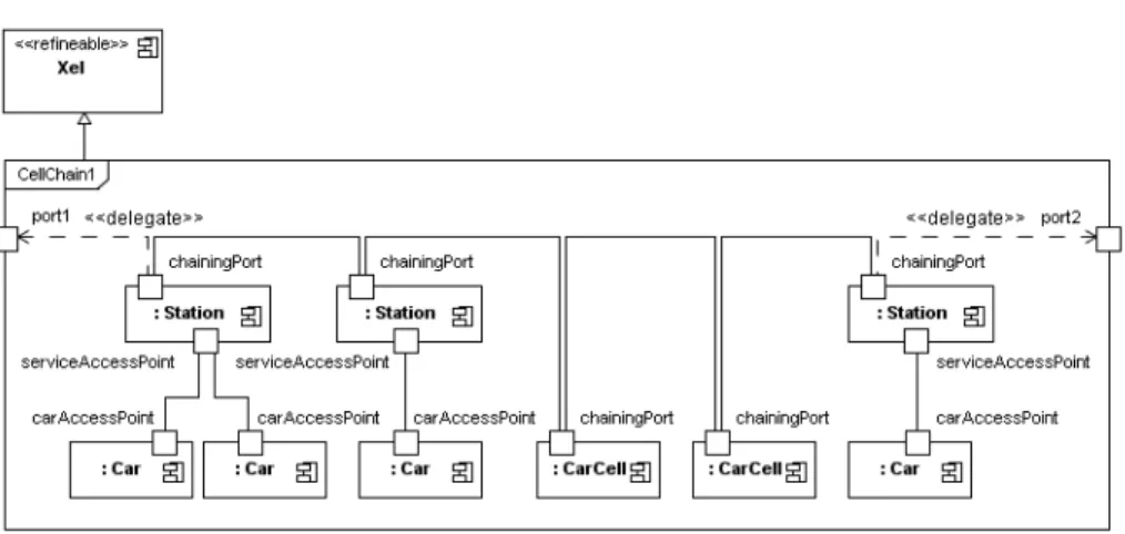
Figure 6 exemplifies how UML4SOAhhfragmentiicomponents can be mapped to ADR designs: hhserviceiiports are mapped to ADR nodes, while the port type determines the node type (e.g. UML types ChainingPort, CarAcccessPort andStationAcccessPortare represented by node types•,◦ and}, respectively). Components are mapped to hyper-edges, where the component type determines the hyper-edge type.
The interface of the design is defined by the ports and the generalisation of thehhfragmentiicomponent. The ports of thehhfragmentiidefine the set of interface nodesVLd, and eachhhdelegatesiiedge defines a maplet of the mapping
id from interface to body nodesVRd. The type of the graph, as defined by the UML4SOA model, is determined by the generalisation of eachhhfragmentii.
Fig. 6.A configuration of theOn Road Connectivity scenario
Modelling Architectural Styles in ADR. Refinable components and non-refinable components of UML4SOA specifications are respectively modelled by non-terminal and non-terminal edges in ADR. Internal structure diagrams and productions are the style definition mechanisms of UML4SOA; they are modelled by ADR design productions. Note however that some of the architectural constraints involved in class diagrams, such as multiplicities, cannot be expressed by type graphs directly. Indeed, type graphs do not impose any multiplicity constraint, i.e. they would amount to a UML [0..∗] multiplicity constraint. A suitable way to impose a multiplicity constraint in ADR is by means of design productions. For instance, in ADR the treatment of sets of cars in the UML4SOA specification via multiplicities is dealt with the design productionsCarandCars(see Fig. 7), which respectively allow to refine a generic set of cars as an empty set, a single car or the union of two other sets. In this way, UML4SOA productions are directly mapped into ADR design productions.
Modelling Reconfigurations under Architectural Styles. We just recall here that one of the advantages of ADR reconfigurations over other graph-based approaches is style-preservation, which is guaranteed by rewrites that do not change the overall type (they can actually change the type of certain sub-parts in the rule derivation of the overall reconfiguration).
Translating UML4SOA reconfiguration rules to ADR in the general case is done by translating the precondition rules, thehhtransformsiileft- and right-hand sides of the rule conclusion, and translating transformation labels into their respective counterparts in ADR. In this process, hhpatternii components are translated to ADR designs by first producing ADR design graphs (replacing components with [0..∗] multiplicities by the corresponding non-terminal hyper-edge, as done in the example withCars) and then parsing the result using the ADR productions generated from the UML4SOA productions.
Fig. 7.Design productions forOn Road Connectivity scenario
We show now a simple example of an ad-hoc network reconfiguration, which is modelled with inductive reconfiguration rules in SOS style. The base reconfigu-ration involves a single car:
CarToCell: Cartocell−→ CarCell
The inductive case we consider is when the union of two collections of cars is reconfigured as the concatenation of the respective reconfigured cells:
CarsToCellChain: x1 tocell −→ x01 x2 tocell −→ x02 Cars(x1, x2) tocell −→ Chain(x01, x02)
Finally, the cell with the station shutting down is reconfigured by:
CellToChain: x
tocell
−→ x0 CarStation(x)−→x0
Obviously, types are not preserved byCarToCellandCarsToCellChainand thus the right- and left-hand sides of the rewriting rule cannot be applied in the same contexts. Type changing allows for the modelling of reconfigurations that lead from one architectural style to another. The last rule CellToChain, instead, is given as a conditional term rewrite rule, where the premise is in its turn a rewrite rule requiring a collection of cars to become a chain cell, while the conclusion actually transforms a chain of cells into a chain of cells. The type is preserved and the silent label makes it applicable in any larger context (unlike style-changing rewrites labelledtocell).
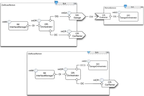
Fig. 8.An SRML diagram before (top) and after (bottom) composition.
4.2 SRML
In this section we provide a formalisation of some aspects of the SENSORIA Reference Modelling Language (SRML) [9]. SRML is inspired by the Service Component Architecture (SCA [13]). Roughly, it provides primitives for modelling composite services and activities whose business logic involves the orchestration of interactions among more elementary components and the invocation of services provided by external parties.
In [4] we presented a formalisation of the design and reconfiguration aspects of SRML based on ADR. The main idea was to define an ADR architectural style of correct SRML diagrams and set of ADR reconfiguration rules correctly modelling the internalisation of services that occurs in SRML, both at design-time (static module composition) and at run-time (dynamic service binding). After recalling the work in [4], this section mainly outlines a formal semantics of the behaviour of SRML specifications based on ADR rules in the form of Synchronised Hyperedge Replacement (SHR).
More precisely, given a SRML specification, first we exploit the translation given in [4] to derive a corresponding ADR design term that evaluates to a particular design, and then we consider the application of SHR rules directly over the design and not over the design term as in the case of reconfiguration. Binding-time reconfigurations in SRML. We consider a scenario that involves an activity OnRoadRepair that takes place in a software system embedded in a vehicle to handle engine failures detected by a sensor. When the activity is
triggered, the system determines the current location of the car by using a GPS device, searches for the closest garage that can ensure minimal levels of repair and call a tow truck, and contacts a car rental service near the garage.
Some architectural elements of SRML are drawn in Fig. 8 and include service modules, service components, wires and interfaces. A module is specified in terms of a number of entities and the way they are interconnected. For example, the activity module shown in Fig. 8 (top-left) involves the following software entities: OR(the orchestrator that coordinates the interactions with the external services) andIM(the component that manages the interactions with the driver). These entities are interconnected through wires, each of which defines an interaction protocol between two entities. Typically, wires deal with the heterogeneity of partners involved in the activity by performing data integration. The activity OnRoadRepair relies on a number of external services that will be discovered on the fly: (1) the service for booking a garage and calling a tow-truck, and (2) the service for booking a rental car. This dependency is made explicit through the requires-interfaces GAandCR, respectively. As illustrated, every activity module declares interfaces of various kind: one and only oneprovides-interface that binds the activity to the application that triggered its execution (e.g.,CRin module RepairService), and a number of requires-interfaces (possibly none) that bind the activity to services that are procured externally when certain conditions become true (e.g., GAin moduleOnRoadRepair). Service modules such asRepairService in Fig. 8 provide a service to the external environment and can be dynamically discovered and invoked (instead of being launched directly by users).
The graphical notation of SRML is inspired by the traditional boxes-and-lines or component-and-connectors notations and elements are shaped as in SCA. The structural constraints, in turn, require modules to be interconnected via external wires such that one of the require interfaces of a module is connected to the provide interface of another one. Inside a module, components and interfaces are connected via internal wires. An SRML architecture is given at the highest level of abstraction by anassembly of modules with possibly some discovered but not yet bound service modules (i.e., they are still connected via external wires). Figure 8 (top) shows the architecture of our scenario with the service module OnRoadRepair, where one of the two required services (namely RepairService, corresponding to the interfaceGA) has been discovered and connected via an external wire (EW).
An example of a reconfiguration in SRML is the composition of (already discovered) interconnected modules into a single module. SRML provides a mechanism to achieve this static reconfiguration, by means of an algorithm that manipulates SRML specifications. As an example, the assembly of Fig. 8 (top) can be composed into the service module depicted in Fig. 8 (bottom), where the wireOCGis derived according to certain composition rules. Such reconfigurations require a proof of correctness w.r.t. style preservation.
The formalization of SRML in ADR given in [4] introduces suitable architec-tural elements for representing service components, internal wires, external wires, provide interface specifications, require interface specifications as terminal edges
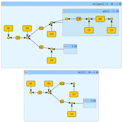
Fig. 9.ADR-view of SRML binding (top) and composition (bottom)
and activity modules, service modules, wrapped modules and their bodies as non-terminal edges. While the interested reader is referred to [4] for full details, we sketch here the basic idea of the modelling. Figure 9 (top) shows the ADR service module and wrapped module corresponding to the SRML diagram in Fig. 8 (top). When a binding is performed, then the wrapped module is plugged-in the service module. SRML composition is then realised via conditional rewrite rules that synthesize a suitable wiring out of the specifications of the require interface and provide interface of the composed modules, according to the internal and external wiring connecting them. The result is shown in Fig. 9 (bottom), where the internal wiringOCGis synthesized out of OG,GA,EW,CR, andCG. Operational Semantics for SRML. To illustrate the SHR modelling of ordinary computational aspects of SRML, let us consider the automotive scenario where the service execution is at the point in which a garage service has been discovered and bound (see Fig. 9 (bottom). The new configuration includes the components and the top/bottom layer interfaces ofOnRoadRepairand those ofRepairService. The representation of a configuration does not include the external provide/require interfaces because external interfaces do not describe an executable process. Note that Fig. 9 presents a simplified form of the actual graphs, where we just
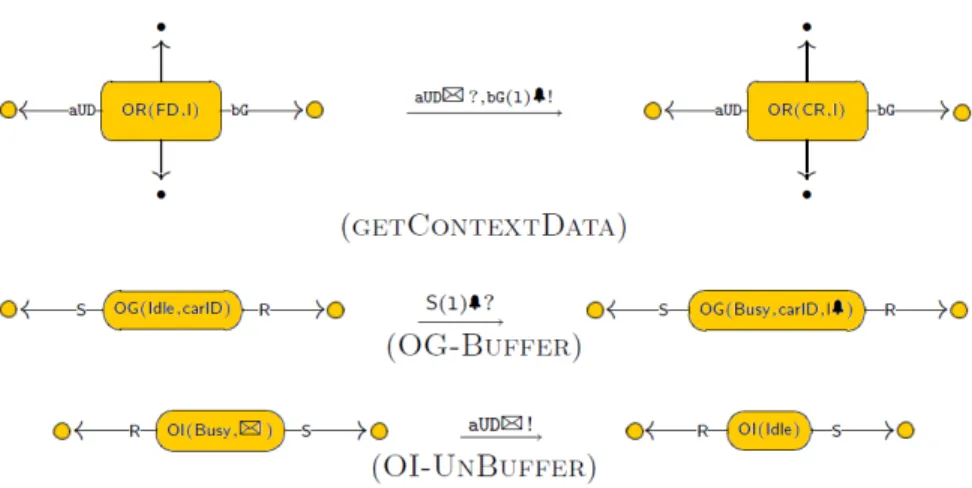
Fig. 10.Some operational rules modelling SRML behaviour
decorate the edges with the component and connector names, while additional information such as the type and state of components or the name of interactions are abstracted away. We shall explicitly represent some of those details when needed.
We continue our illustration with the representation of a transition getCon-textDataof the business roleOrchestrator(to retrieves the data of the driver, for example from InterfaceManager) as a rule in SHR style (see Fig. 10): the transition label witnesses that the component is ready to receive (?) a reply event (B) on interaction askUsrDetails (aUD) and simultaneously send (!) an
initiation event () on interaction bookGarage(bG), while changing state from FD(FAILURE DETECTED) toCR(CONTEXT RECEIVED).
Note that the graphical representation of the rules is simplified for the sake of readability. For instance, not all interactions (represented here as labelled tentacles) are drawn. We put state information (local state, variables) as edge labels in tuples, and we neglect some of the parameters of the interactions. The type of interactions is drawn using different node types, so to forbid any mismatched connection: e.g. we use•fors&rand◦forr&s.
Observe that the various events involved in the transition (i.e. the trigger and the events to be sent) are put on the rule label. In this particular case the transition guard is implicit in the edge label (containing the state of the component). In general, guards are modelled as side conditions. Effects, instead, are just the resulting edge label. Transitions are thus given an atomic semantics: trigger, effects andsendsare executed simultaneously.
SHR rules can be synchronised together using different styles. In our case, we follow the Milner style, where rule synchronisation requires an action being sent on a node to be synchronised with a corresponding co-action on the same node. Note that since a rule can involve actions of more than one node among those attached to an edge, multiple synchronisations are possible. In our example, rule
getContextData can only be fired if the surrounding connectors are able to perform the corresponding co-actions.
For instance, in the surroundings of the orchestrator component we find two connectors involved in transitiongetContextData, namely OGandOI. The binding is such that thebookGarageandaskUserDetailsinteractions of the orchestrator are assigned to rolesSof connectorsOGandIM, respectively.
All the rules that we need are such that the left-hand side and the right-hand side differ only in the label of the edge, meaning that only the state is changed, but neither the interface nor its bindings, i.e. the type is preserved. This condition is enough to guarantee that the overall design term is not affected by the application of operational rules. Part of the behaviour of the connectors include rules to buffer and unbuffer events (see Fig. 10). For instance, consider the rule to buffer the init event: it changes the state of the connector fromIdle toBusy(buffered), and the received parameterlis enqueued (it is just part of the edge label).
A straightforward ternary synchronisation allow us to derive the rewrite
−→
out from rules getContextData, IO-UnBuffer and OG-Buffer. Such derivation synchronises a component with two of its attached connectors. In some cases, connectors might synchronise with both parties such that complex synchronisations involving multiple components and connectors are possible.
4.3 Software Modes
In this section, we consider the ADR modelling of Software Architecture Modes, as presented in [11]. There, a mode abstracts a specific set of services that must interact for the completion of a specific subsystem task. Modes are first-class archi-tectural ingredients that govern the architecural constraints and reconfiguration mechanisms of a software system.
Service Modes build upon and extend the concept of Software Architecture Modes with that of behaviour and policy specifications for service adaptation and dynamic reconfiguration. Service Modes are specifically aimed at specifying “operational adaptation” for a service-oriented system. They are based upon an evolving set of scenarios describing service component architecture, behaviour and events which trigger reconfiguration, whilst upholding quiescence in service operation.
We illustrate the ADR formalisation of modes with a road assistance scenario of the automotive case study. In the scenario, cars are equipped with navigation
Fig. 11.The RPS subsytem production
Fig. 12.Building detour convoy groups
systems connected to a road assistance service platform. The focus of our example is on the Route Planning Subsystem (RPS) which is in charge of providing guiding indications to the driver. The RPS has three modes of operation:Autonomous, i.e. connected to the GPS to establish the route,Convoy, i.e. following another car, Detour, i.e. following indications from the Highway Emergency system (HES).
The components that form the RPS subsystem are the Global Positioning System (GPS) the Highway Emergency System (HES), the Route Planning Subsystem (RPS), the Planner (P), the User Interface (UI), and the User Prompt (UP). Some of these (sub)components can be in a different mode. For instance, P can be in modes P-Master or P-Slave, while the user interface UI and prompt UP can be in modesEnable orDisable.
Informally, the main architectural constraints require that an RPS must be composed of a P, an UI and an UP. The mode of the RPS depends on the modes of its constituents. Convoys are formed by a leader RPS followed by RPSs in convoy mode. Leaders can be either in autonomous or detour mode. Autonomous RPSs are connected to the GPS. Detour RPSs are connected to the HES.
The main idea of the formalisation with ADR is to encode a software class as a type T and its various modes as subsorts T-M of T. Additional types can stand for complex constructions (shapes, styles, patterns) such as sequences, sets or trees. Such types can be used to define composition operations that determine the valid configurations. Mode types play a relevant role in reconfigurations.
Fig. 13.Building RPSs in various modes
Structural constraints are captured by a set of ADR design productions that build conformant configurations. For instance, we use productions to build systems (see Fig. 11) and Detour Convoy Groups (DCG) either as a single RPS in detour mode followed by a sequence of RPSs in convoy mode (Fig. 12, left) or two DCGs (Fig. 12, right). Dotted lines between ports denote interface exposure and not binding of actual ports (denoted by straight lines). The figures are drawn according to Darwin notation, but the correspondence with our designs is immediate (ports are nodes, boxes are edges and the flattening axioms apply if the contour of a box is dotted), except for the fact that each port binding actually corresponds to a terminal edge b. Whenever necessary (i.e., not implied by flattening axioms), we assume the expected properties for the operations to hold (commutativity, associativity, etc.). Similar operations are used to build Autonomous Convoy Groups (ACG): they can be built from an RPS in autonomous mode (RPS-autonomous) followed by a sequence of RPSs in convoy mode (CS) or from two ACGs. Productions are also used to build a CS as single RPS in convoy mode or as the concatenation of CSs.
There are also productions to build RPSs in various modes (see Fig. 13 for the productions needed in the examples that concludes this section). An RPS in autonomous mode is a composite component with a P in master mode, an UP in enable mode and an UI in enabled mode. An RPS in detour mode is a composite component with a P in master mode, an UP in disable mode and an UI in enabled mode. An RPS in convoy mode is a composite component with a P in slave mode, an UP in enable mode and an UI in enabled mode. Basically,
each pair (component type,mode) has a corresponding constructor and ADR type. Constructors for HES and GPS are similar.
The allowed RPS reconfigurations are from Detour to Autonomous mode (and back) and from Convoy to Autonomous and Detour mode (and back). However, RPS components should not reconfigure independently: their constituents and contexts should reconfigure such that architectural constraints are respected.
For instance, a single RPS in detour mode is moved from the group of RPSs in detour mode to the group of convoys if that RPS reconfigures itself from mode detour to mode autonomous, i.e. if its UP reconfigures from disable to enable mode. Exploiting our design algebra, the corresponding rules can be written as the following (labelled) conditional term rewrite rules:
upd−→d2e upe
Xupd−→d2e Xupe
rpsd(Xpm,Xupd,Xuie)−→d2a rpsa(Xpm,Xupe,Xuie) Xrpsd −→d2a Xrpsa
system(Xgps,Xhes,Xacg,group(single(Xrpsd,Xcs),Xdcg))
−→system(Xgps,Xhes,group(Xacg,single(Xrpsd,Xcs)),Xdcg)
5
Conclusion
This chapter collects results from [3–6, 1]. In particular, we have provided an overview of main ADR features and the ADR representation of UML4SOA, SRML and Software Modes; the latter being original to this contribution. The formal semantics prepares the ground towards tool support for analysis and verification from the very early stages of modeling. Thus, ADR offers a comprehensive and pragmatic yet theoretically well founded approach to software engineering for service-oriented systems. Our current efforts are aimed at completing our tool support. First, by automatising the translation of high-level specifications in the considered languages, possibly by means of Maude-supported, MOF-based model transformations. Second, by upgrading the prototypical implementation of ADR into a tool that can be used to formally analyse ADR models either specified directly or transformed from other models.
In fact, ADR specifications can be exploited to perform formal specification and verification based on techniques developed, e.g. for term rewrite systems and graph transformation systems. For instance, ADR specifications can be encoded into Rewriting Logic [12] and benefit from Maude’s built-in tools.
References
1. R. Bruni, M. H¨olzl, N. Koch, A. Lluch Lafuente, P. Mayer, U. Montanari, A. Schroeder, and M. Wirsing. A service-oriented UML profile with formal support. InThe 7th International Joint Conference on Service Oriented Computing (IC-SOC/ServiceWave’09), volume 5900 ofLecture Notes in Computer Science. Springer Verlag, 2009.
2. R. Bruni and A. Lluch Lafuente. Ten virtues of structured graphs. InProceedings of the 8th International Workhshop on Graph Transformation and Visual Modeling Technique (GT-VMT’09), volume 18 ofElectronic Communications of the EASST. ECEASST, 2009.
3. R. Bruni, A. Lluch Lafuente, and U. Montanari. Hierarchical design rewriting with Maude. In G. Rosu, editor,Proceedings of the 7th International Workshop on Rewriting Logic and its Applications (WRLA’08), volume 238 (3) ofElectronic Notes in Theoretical Computer Science, pages 45–62. Elsevier, 2009.
4. R. Bruni, A. Lluch Lafuente, U. Montanari, and Emilio Tuosto. Service oriented architectural design. InProceedings of the 2nd International Symposium on Trust-worthy Global Computing (TGC’07), volume 4912 ofLecture Notes in Computer Science, pages 186–203. Springer Verlag, 2007.
5. R. Bruni, A. Lluch Lafuente, U. Montanari, and E. Tuosto. Style Based Architectural Reconfigurations. Bulletin of the European Association for Theoretical Computer Science (EATCS), 94:161–180, February 2008.
6. A. Bucchiarone, R. Bruni, S. Gnesi, and A. Lluch Lafuente. Graph-Based Design and Analysis of Dynamic Software Architectures. In Concurrency, Graph and Models. Festschrift in honor of Ugo Montanari, volume 5065 ofLecture Notes in Computer Science. Springer Verlag, 2008.
7. A. Corradini, U. Montanari, F. Rossi, H. Ehrig, R. Heckel, and M. L¨owe. Algebraic Approaches to Graph Transformation - Part I: Basic Concepts and Double Pushout Approach. In G. Rozenberg, editor,Handbook of Graph Grammars and Computing by Graph Transformation, pages 163–246. World Scientific, 1997.
8. G. L. Ferrari, D. Hirsch, I. Lanese, U. Montanari, and E. Tuosto. Synchronised hyperedge replacement as a model for service oriented computing. In F. S. de Boer, M. M. Bonsangue, S. Graf, and W. P. de Roever, editors, Proceedings of the 4th International Symposium on Formal Methods for Components and Objects (FMCO’05), volume 4111 ofLNCS, pages 22–43. Springer, 2006.
9. J. L. Fiadeiro, A. Lopes, and L. Bocchi.Rigorous Software Engineering for Service-Oriented Systems - Results of the SENSORIA project on Software Engineering for Service-Oriented Computing, chapter 1.2 The Sensoria Reference Modelling Language. Lecture Notes in Computer Science. Springer Verlag, 2009.
10. H. Foster, L. G¨onczy, N. Koch, P. Mayer, C. Montangero, and D. Varr´o. Rigorous Software Engineering for Service-Oriented Systems - Results of the SENSORIA project on Software Engineering for Service-Oriented Computing, chapter 1.1 UML for service-oriented systems. Lecture Notes in Computer Science. Springer Verlag, 2009.
11. D. Hirsch, J. Kramer, J. Magee, and S. Uchitel. Modes for software architectures. In V. Gruhn and F. Oquendo, editors,Proceedings of the 3rd European Workshop on Software Architecture (EWSA’06), volume 4344 ofLecture Notes in Computer Science, pages 113–126. Springer Verlag, 2006.
12. J. Meseguer and G. Rosu. The rewriting logic semantics project. Theoretical Computer Science, 373(3):213–237, 2007.
13. Service Component Architecture. http://osoa.org.
14. M. Shaw and D. Garlan. Software architecture: Perspectives on an emerging discipline. InPrentice Hall, NJ. USA, 1996.