Software for Auto-Generating Electrode Block Order Sheet:
Study Case in Mold Machining Workshop
Tetuko Kurniawan
1,a, Yosep Purnama
2,b1,2
Study Program of Mechanical Engineering, President University, Ki Hajar Dewantara Rd., Jababeka City, Bekasi 17550, Indonesia.
a
[email protected]*; [email protected]
Abstrak. Dalam proses pembuatan cetakan, beberapa ratusan elektroda diperlukan untuk proses
EDM. Produksi elektroda memakan waktu dan rawan kesalahan ketika datang untuk menciptakan Electrode Blok Orde Lembar. software baru dikembangkan untuk membuat proses otomatis untuk menghasilkan Lembar Electrode Blok Orde bahwa mengurangi konsumsi waktu dan menghilangkan kesalahan manusia selama proses tersebut. Dengan aplikasi perangkat lunak, konsumsi waktu untuk membuat Electrode Blok Orde Lembar berkurang 80% dan kesalahan manusia yang terlibat dalam proses tersebut dieliminasi.
Kata kunci. EDM, cetakan, software, otomatisasi, elektroda, pembuatan
Abstract. In a mold manufacturing process, few to hundreds electrode is required for the EDM process. The electrode production is time consuming and it prone to errors when it comes to creating Electrode Block Order Sheet. New software was developed to create automated process to generated Electrode Block Order Sheet that reduce the time consumption and eliminate human errors during the process. By the application of the software, time consumption to create Electrode Block Order Sheet is reduced by 80% and human error involved in the process is eliminated.
Keywords. EDM, mold, software, automation, electrode, manufacture
Introduction
In mass production of various products such as smartphone, TV, motorcycle, cars, etc; there are various manufacturing technology involved to create single component out of hundreds or thosands components of a product. One technology that commonly used for mass production of plastic components is the plastic injection process. This process uses melted plastic injected into a mold and cool it down to create various shape of plastic product. Mold technologies allow the production of plastic part with a relatively short cycle time, high degree of reproducibility and capabilities to make various shapes. Mold technology has been growing rapidly and plays important role in the manufacture industry [1]. Manufacturing a high quality mold within acceptable lead limit and mold cost will determine the productivity of a product thus it is one of the main factor effecting product prices. Because of that, improvements of mold manufacturing process system and integration of computer aided technique in mold manufacture has been subjected to the research in manufacturing technology [2, 3].
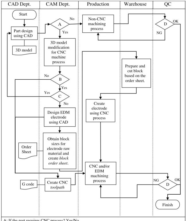
Manufacturing a mold is quite difficult task since it requires large team with experienced mechanical engineer and proven machining skills. Figure 1 shows common mold part manufacturing process with teams involved in the process. Each mold part is designed by using Computer Aided Design (CAD) software. The design is then need to be evaluated for which machining process suitable to produce the part. Machining process can be classified into three different types. The first type is the conventional machining process that is human operates manual machines such as milling machine, numerical control (NC) milling machine, lathe machine etc. The second type is the computer aided machining process. Computer is embedded within the machine to control the machining process. Computer Numerical Control (CNC) milling or lathe machine is commonly used in the industry. The third type is the non-conventional machining process. Engine Discharge Machining (EDM) is one of the commonly used in mold manufacturing. A single part
may be manufacture by one or many of three machining type. After a part was machined, quality inspection is conducted before it is assembled into one mold.
Figure 1. Flow chart of mold manufacturing process.
CAD Dept. CAM Dept. Production Warehouse QC
3D model Part design using CAD Start A 3D model modification for CNC machine process B C Design EDM electrode using CAD Obtain block sizes for electrode raw material and create block order sheet. Order Sheet Non-CNC machining process D Prepare and cut block based on the order sheet. Create electrode using CNC process CNC and/or EDM machining process Finish No Yes OK NG G code Yes No Create CNC toolpath Yes No D OK NG
A: If the part requires CNC process? Yes/No B: If the part requires EDM? Yes/No
C: If the part design could be modified so that it will not require EDM process? Yes/No D: If the finished part quality good? OK/NG
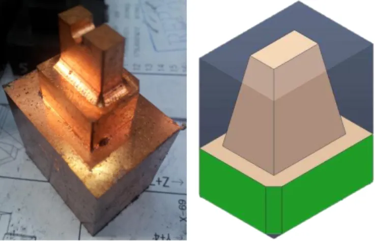
When a part requires EDM process, an electrode must be made before the part can be processed in EDM (see Figure 1). One mold may need few to hundreds electrode. To create an electrode, it requires a whole design, material preparation and machining process, thus it consumes considerably a lot time [4]. A block of electrode material with required size needs to be prepared before manufacture the electrode. Figure 2 shows an electrode and illustration of electrode block. Block can be made from brass, copper and copper alloys, graphite, molybdenum, silver, and tungsten. To create electrode block, CAM team must provide to the warehouse team correct information about the part name and block size. Typically, an order sheet of block specification was made manually causing the process heavily time consuming and the order sheet is prone to errors. Therefore, there is high need to develop software to automate the process of creating block order sheet. This research presents the development of a new software that useful for automatic creation of electrode block material order sheet. With the use of this software, human errors within the process can be eliminated and time needed to do the process will be largely reduced.
Figure 2. EDM electrode and illustration of block for making the electrode
Method
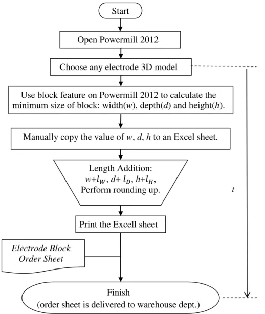
The Manual Process. Figure 3 shows the flow chart of original process for creating order sheet. In this study case Delcam® PowerMILL 2012 was used as Computer Aided Manufacturing (CAM) software. In PowerMILL 2012, block feature was used to estimate the minimum block sizes: width (w), depth (d) and height (h). The minimum block sizes are then recorded manually to a Microsoft Excel Sheet. In the Excel sheet, a predetermined length (lw, ld, lh) was added to each w, d and h, respectively as described in below equations:
(1)
(2)
(3)
where wb, db, hb is the block width, depth and height, respectively. lw, ld and lh are the length adjustment with the purpose to provide enough space for the clamp fixture and enough distance for material removal. lw and ld usually about 10mm, while lh is about 20mm.
Then, wb, db, hb value need to be rounding off or rounding up. This rounding rule varies for each mold manufacturer and it depends on the availability of block rawa material. However, one example of rounding rules is given below. If x is the unit numbers wb (for example: wb = 21.50, then x = 1), the rounding rules are:
for 0 ≤ x < 2, rounding off x to x = 0; for 2 ≤ x < 7, rounding x to x = 5; for 7 ≤ x < 10, rounding up x to x = 10.
For example, if wb = 31.50 mm, after rounding wb = 30.00mm. After rounding number process, the Excel sheet that contains block size data and part name is printed and it is delivered to warehouse department for preparation (see also Figure 1).
The sheet is called as Electrode Block Order Sheet. Manual process of copying w, l, h to Excel sheet causes time loss and it is prone to error. The erroneous Order Sheet will cause the warehouse department to create erroneous block. The block size error only can be detected during machining process of the electrode block. The erroneous block will be abolished and new block must be made. This cause material and time loss. t in Figure 3 is the time measured from the process of loading electrode 3D model in PowerMILL 2012 until the Order Sheet is generated.
Figure 3. The manual process to create electrode block order sheet from Power Mill to Microsoft Excel. t is the time measured from begining process to end.
Finish
(order sheet is delivered to warehouse dept.) Use block feature on Powermill 2012 to calculate the minimum size of block: width(w), depth(d) and height(h).
Length Addition: w+𝑙𝑊, d+ 𝑙𝐷, h+𝑙𝐻, Perform rounding up.
Print the Excell sheet Electrode Block
Order Sheet
Start
Open Powermill 2012
Choose any electrode 3D model
Manually copy the value of w, d, h to an Excel sheet.
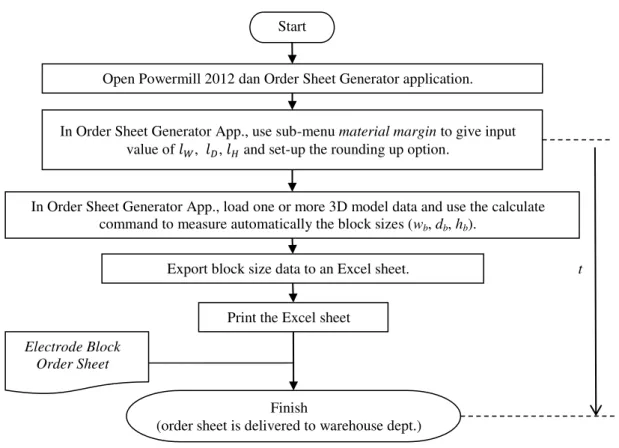
The auto-generated process. Figure 4 shows the auto-generated flow process. New software called Order Sheet Generator is used. PowerMILL 2012 is still need to be open because the new software works as plug-in to the PowerMILL 2012. After PowerMILL 2012 is open, the next subsequent process uses only the Order Sheet Generator. The next step is to set up the value of lw, ld and lh. Afterwards, user needs to set up the rounding option. Then open an electrode 3D model in the App. This App may process more than one 3D model at a time (batch process). After 3D model(s) is loaded, the App continues to calculate and directly create the Excel Spread sheet that contains part name, wb, db and hb. The possibility of error is likely to be very small since the App reads directly from 3D model data. The time consumed also greatly reduced. t from the manual process, single auto-generated process and batch auto-generated process are measured from 22 times trial and will be presented in the next section.
Figure 4. Auto-generated order sheet process. t is the time measured from begining process to end.
Start
Open Powermill 2012dan Order Sheet Generator application.
In Order Sheet Generator App., load one or more 3D model data and use the calculate command to measure automatically the block sizes (wb, db, hb).
Export block size data to an Excel sheet.
In Order Sheet Generator App., use sub-menu material margin to give input value of 𝑙𝑊, 𝑙𝐷, 𝑙𝐻 and set-up the rounding up option.
Print the Excel sheet
Finish
(order sheet is delivered to warehouse dept.)
Electrode Block Order Sheet
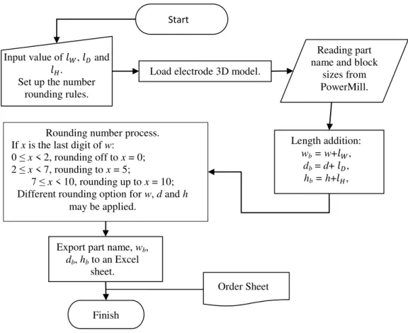
Figure 5. Algorithm for auto generating order sheet program.
Software Development. The flow-chart algorithm of the software is shown in Figure 5. The application was written in Microsoft Visual Studio 2010. In the beginning, user must give input value of lw, ld and lh. Next, user need to set up the rounding rules for wb, db, hb. After finish the set-up, 3D model is loaded. Multiple files can be loaded at once. The App was programmed to read 3D model data provided by the PowerMILL 2012. This process is allowed by using the PowerSolutionDOTNetOLE.dll file provided by Delcam. Reading minimum block size, calculation & rounding number of block size and exporting the block size to Excel File is automatically done by the Application. The application greatly simplifies the Order Sheet generation process.
The Guide User Interface (GUI) of the main program is shown in Figure 6. The coding of the main program in Visual Studio 2010 is written below:
Imports PowerSolutionDOTNetOLE.clsPowerMILLOLE Imports PM = PowerSolutionDOTNetOLE.clsPowerMILLOLE Public Class Form1
Inherits System.Windows.Forms.Form
Private Sub Button1_Click(ByVal sender As System.Object, ByVal e As System.EventArgs) Handles Button1.Click
OpenFileDialog1.Multiselect = True OpenFileDialog1.FileName = "" OpenFileDialog1.DefaultExt = ".stp" OpenFileDialog1.AddExtension = True
OpenFileDialog1.Filter = "Step Files (step)|*.stp|iges Files (iges)|*.igs|Dgk Files (Dgk)|*.Dgk"
If OpenFileDialog1.ShowDialog = Windows.Forms.DialogResult.OK Then Dim filesEnum As IEnumerator
filesEnum = OpenFileDialog1.FileNames.GetEnumerator() While filesEnum.MoveNext
ListView1.Items.Add(filesEnum.Current) End While
Load electrode 3D model.
Finish Input value of 𝑙𝑊, 𝑙𝐷 and
𝑙𝐻. Set up the number
rounding rules.
Start
Reading part name and block
sizes from PowerMill. Length addition: wb = w+𝑙𝑊, db = d+ 𝑙𝐷, hb = h+𝑙𝐻,
Export part name, wb, db, hb to an Excel
sheet.
Order Sheet Rounding number process.
If x is the last digit of w:
0 ≤ x < 2, rounding off to x = 0;
2 ≤ x < 7, rounding to x = 5;
7 ≤ x < 10, rounding up to x = 10; Different rounding option for w, d and h
End If End Sub
Private Sub Form1_FormClosing(ByVal sender As Object, ByVal e As System.Windows.Forms.FormClosingEventArgs) Handles Me.FormClosing
Form3.Show () End Sub
System.EventArgs) Handles MyBase.Load End Sub
Private Sub cal_3d()
If ListView1.Items.Count = 0 Then
MsgBox("Select the Model to process.") Return Else PM.Connect() PM.SetWindowState(PowerSolutionDOTNetOLE.clsGlobalEnumerations.enum_WindowStateType.p sMaximise) Me.WindowState = FormWindowState.Minimized
For i As Integer = 0 To ListView1.Items.Count – 1 ProgressBar1.Minimum = 0
ProgressBar1.Maximum = ListView1.Items.Count ProgressBar1.Value = i + 1
Dim ModelDir As String = ListView1.Items.Item(i).SubItems(0).Text PM.Execute("DIALOGS MESSAGE OFF")
PM.Execute("DIALOGS ERROR OFF")
PM.Execute("IMPORT MODEL FILEOPEN '" & ModelDir & "'")
Dim NumModel As Integer, Models() As String, ActiveModel As Integer
PM.GetEntityList(PM.enumPowerMILLEntityType.pmModel, NumModel, Models, ActiveModel) Dim Mdl As String = Models(0)
PM.Execute("VIEW MODEL ; SHADE NORMAL")
PM.Execute("EDIT MODEL '" & Mdl & "' SELECT SURFACE") Call Block_Calculate()
PM.Execute("DELETE MODEL ALL") PM.Execute("DELETE LEVEL ALL") Next
End If Me.Hide() Form2.Show() End Sub
Private Sub Set_Datagrid()
Form2.DataGridView1.Columns(0).Width = 150 Form2.DataGridView1.Columns(1).Width = 50 Form2.DataGridView1.Columns(2).Width = 50 Form2.DataGridView1.Columns(3).Width = 50 End Sub
Private Sub Button3_Click(ByVal sender As System.Object, ByVal e As System.EventArgs) Handles Button3.Click
Form3.Show() Me.Hide() End Sub
Private Sub Button2_Click(ByVal sender As System.Object, ByVal e As System.EventArgs) Handles Button2.Click
Call cal_3d() End Sub
Private Sub Button4_Click(ByVal sender As System.Object, ByVal e As System.EventArgs) Handles Button4.Click
Form4.Show() Me.Hide() End Sub End Class
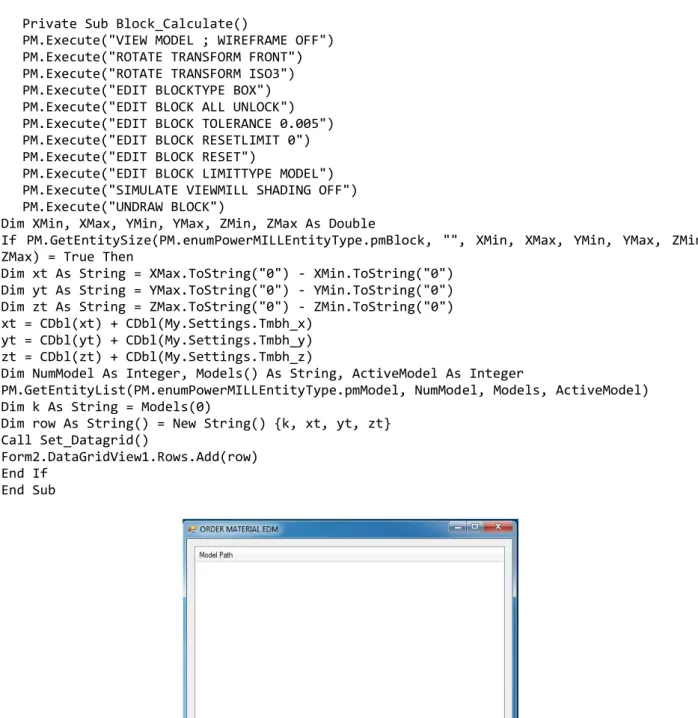
Private Sub Block_Calculate()
PM.Execute("VIEW MODEL ; WIREFRAME OFF") PM.Execute("ROTATE TRANSFORM FRONT") PM.Execute("ROTATE TRANSFORM ISO3") PM.Execute("EDIT BLOCKTYPE BOX") PM.Execute("EDIT BLOCK ALL UNLOCK") PM.Execute("EDIT BLOCK TOLERANCE 0.005") PM.Execute("EDIT BLOCK RESETLIMIT 0") PM.Execute("EDIT BLOCK RESET")
PM.Execute("EDIT BLOCK LIMITTYPE MODEL") PM.Execute("SIMULATE VIEWMILL SHADING OFF") PM.Execute("UNDRAW BLOCK")
Dim XMin, XMax, YMin, YMax, ZMin, ZMax As Double
If PM.GetEntitySize(PM.enumPowerMILLEntityType.pmBlock, "", XMin, XMax, YMin, YMax, ZMin, ZMax) = True Then
Dim xt As String = XMax.ToString("0") - XMin.ToString("0") Dim yt As String = YMax.ToString("0") - YMin.ToString("0") Dim zt As String = ZMax.ToString("0") - ZMin.ToString("0") xt = CDbl(xt) + CDbl(My.Settings.Tmbh_x)
yt = CDbl(yt) + CDbl(My.Settings.Tmbh_y) zt = CDbl(zt) + CDbl(My.Settings.Tmbh_z)
Dim NumModel As Integer, Models() As String, ActiveModel As Integer
PM.GetEntityList(PM.enumPowerMILLEntityType.pmModel, NumModel, Models, ActiveModel) Dim k As String = Models(0)
Dim row As String() = New String() {k, xt, yt, zt} Call Set_Datagrid()
Form2.DataGridView1.Rows.Add(row) End If
End Sub
Figure 6. GUI of the main program.
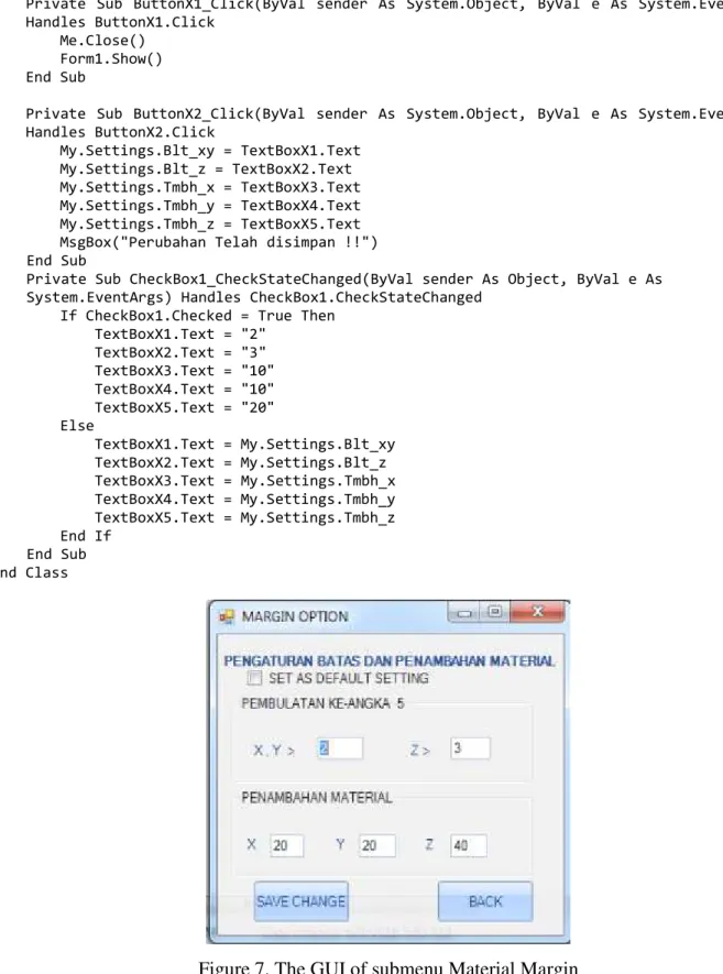
The submenu Material Margin has its own GUI and coding for inputing the value of , , and rounding rules. The GUI is shown in Figure 7, while the coding in Visual Studio 2010 is shown below:
Public Class Form4
Private Sub Form4_FormClosed(ByVal sender As Object, ByVal e As System.Windows.Forms.FormClosedEventArgs) Handles Me.FormClosed
Form1.Show() End Sub
Private Sub Form4_Load(ByVal sender As System.Object, ByVal e As System.EventArgs) Handles MyBase.Load
TextBoxX1.Text = My.Settings.Blt_xy TextBoxX2.Text = My.Settings.Blt_z
TextBoxX3.Text = My.Settings.Tmbh_x TextBoxX4.Text = My.Settings.Tmbh_y TextBoxX5.Text = My.Settings.Tmbh_z End Sub
Private Sub ButtonX1_Click(ByVal sender As System.Object, ByVal e As System.EventArgs) Handles ButtonX1.Click
Me.Close() Form1.Show() End Sub
Private Sub ButtonX2_Click(ByVal sender As System.Object, ByVal e As System.EventArgs) Handles ButtonX2.Click My.Settings.Blt_xy = TextBoxX1.Text My.Settings.Blt_z = TextBoxX2.Text My.Settings.Tmbh_x = TextBoxX3.Text My.Settings.Tmbh_y = TextBoxX4.Text My.Settings.Tmbh_z = TextBoxX5.Text MsgBox("Perubahan Telah disimpan !!")
End Sub
Private Sub CheckBox1_CheckStateChanged(ByVal sender As Object, ByVal e As System.EventArgs) Handles CheckBox1.CheckStateChanged
If CheckBox1.Checked = True Then TextBoxX1.Text = "2" TextBoxX2.Text = "3" TextBoxX3.Text = "10" TextBoxX4.Text = "10" TextBoxX5.Text = "20" Else TextBoxX1.Text = My.Settings.Blt_xy TextBoxX2.Text = My.Settings.Blt_z TextBoxX3.Text = My.Settings.Tmbh_x TextBoxX4.Text = My.Settings.Tmbh_y TextBoxX5.Text = My.Settings.Tmbh_z End If End Sub End Class
Figure 7. The GUI of submenu Material Margin
New window appears after calculation of block size finished. The window contains the data that will be exported to the Excel spreadsheet: wb, wd, wh, part name and material type. The GUI is shown in Figure 8. The coding written in Visual Studio 2010 is shown below:
Imports System.Data.OleDb
Imports Excel = Microsoft.Office.Interop.Excel Public Class Form2
Private Sub Button1_Click(ByVal sender As System.Object, ByVal e As System.EventArgs) Handles Button1.Click
Export_total() End Sub
Public Sub Export_total()
Dim saveFileDialog1 As System.Windows.Forms.SaveFileDialog saveFileDialog1 = New System.Windows.Forms.SaveFileDialog() saveFileDialog1.FileName = "ORDER SHEET 1"
saveFileDialog1.Filter = "Excel 97-2003 Workbook(*.xls) |*.xls;*.rtf|Excel Workbook(*.xlsx) |*.xlsx| All File(*.*) |*.*"
Dim APP As New Excel.Application Dim worksheet As Excel.Worksheet Dim workbook As Excel.Workbook Try
If saveFileDialog1.ShowDialog() = DialogResult.OK Then Dim oldCI As System.Globalization.CultureInfo =
System.Threading.Thread.CurrentThread.CurrentCulture System.Threading.Thread.CurrentThread.CurrentCulture = NewSystem.Globalization.CultureInfo("en-US")
TextBoxX1.Text = saveFileDialog1.FileName workbook =
APP.Workbooks.Open(Application.StartupPath & "\Form\PartlistEDM.xlsx") worksheet = workbook.Worksheets("EDM_ORDER")
For a = 1 To Me.DataGridView1.RowCount
worksheet.Cells(a + 2, 1) = Me.DataGridView1.Rows(a - 1).Cells("Column2").Value worksheet.Cells(a + 2, 2) = Me.DataGridView1.Rows(a - 1).Cells("Column3").Value worksheet.Cells(a + 2, 3) = Me.DataGridView1.Rows(a -1).Cells("Column4").Value worksheet.Cells(a + 2, 4) = Me.DataGridView1.Rows(a - 1).Cells("Column5").Value Next APP.ActiveWorkbook.SaveAs(TextBoxX1.Text) APP.Visible = True System.Threading.Thread.CurrentThread.CurrentCulture = oldCI Else saveFileDialog1.FileName = Nothing End If Catch ex As Exception MessageBox.Show(ex.Message) End Try End Sub
Public Shared Sub ReleaseObject(ByVal obj As Object) End Sub
Private Sub Button3_Click(ByVal sender As System.Object, ByVal e As System.EventArgs) Handles Button3.Click
Me.Close() Form1.Close() Form3.Show() End Sub
Private Sub Form2_FormClosed(ByVal sender As Object, ByVal e As System.Windows.Forms.FormClosedEventArgs) Handles Me.FormClosed
Form1.Close() Form3.Show()
End Sub
Private Sub Form2_Load(ByVal sender As System.Object, ByVal e As System.EventArgs) Handles MyBase.Load
End Sub End Class
Figure 8. GUI of order sheet set-up.
Results and Discussion
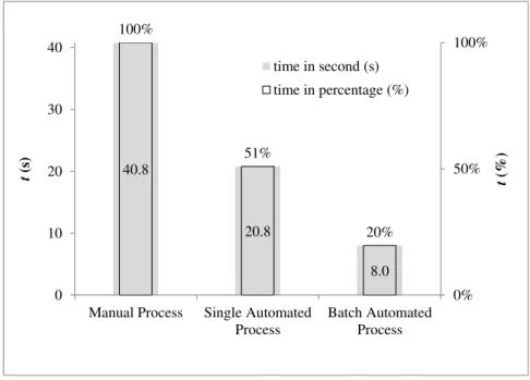
Figure 9 shows the comparison of average time to create an Order Sheet for three different methods: manual process, single file automated process and multiple files (batch) automated process. The average time shown in Figure 9 is measured from 22 different electrode 3D models. For manual and single automated processes, each cycle only loads one electrode 3D models and creates one Order Sheet. Thus, by the end of experiment, 22 distinct Order Sheet is produced. For the batch automated process, all 22 electrode 3D models are loaded at once in the App., thus, by the end of experiment only one Order Sheet is created that consisted of 22 different block data. As shown in Figure 6, the average time per single part that took about 40 seconds in manual process can be reduced to about 8 seconds in batch automated process. The amount of time saved by the batch automated process can be up to 80% or more.
The time is greatly reduced by the eliminating human activity to read and copy data manually from PowerMILL 2012 to Excel spreadsheet. The capability of batch process also significantly reduces time consumption. During the experiment, the auto-generated process has not produces any error of the block data.
Figure 7. t comparison between manual process, single automated process and batch automated process.
40.8 20.8 8.0 100% 51% 20% 0% 50% 100% 0 10 20 30 40
Manual Process Single Automated Process Batch Automated Process t (% ) t (s) time in second (s) time in percentage (%)
Conclusion
The problem for creating Electrode Block Order Sheet is solved by the development of new software. Time consumption can be reduced by 80% or more by the use of the Order Sheet Generator Application. It also eliminate the human error occurs in the original manual process. At present research, the current software only can be used together with Delcam PowerMILL series. However, the algorithm can be developed so that it can be used for other CAM software. With the aid of computing science, new automated process in mold manufacturing can be produced. The automated process in general will eliminate the human error factors and reduce significantly the time consumption of a process.
References
[1] P. Fallböhmer, T. Altan a, H. K. Tönshoff, T. Nakagawa, Survey of the die and mold manufacturing industry - practices in Germany, Japan, and the United States, J. of materials Processing Technology 59 (1996) 158-168.
[2] T. Altan, B. Lilly, Y.C. Yen, Manufacturing of Dies and Molds, J. CIRP Annals – Manufacturing Technology 50 (2001) 404-422.
[3] R. S. Lee, Y. M. Chen, C. Z. Lee, Development of a concurrent mold design system: a knowledge-based approach, J. Computer Integrated Manufacturing Systems 10 (1997) 287-307. [4] X. M. Ding , J.Y.H. Fuh , K.S. Lee , Y.F. Zhang & A.Y.C. Nee, A computer-aided EDM electrode design system for mold manufacturing, Intenational Journal of Production Research 38 (2000) 3079-3092.