The 1st International Conference on Advanced Engineering and Technology - 2018
The Use of Box Culvert Precast as a Main Bridge Structure in
Arterial Highway Road:
An Analysis Study
J Propika1, L L Lestari1 and J F G Muti1 1
Department of Civil Engineering, Institut Teknologi Adhi Tama Surabaya, Surabaya 60117, Indonesia
Abstract. A bridge is a construction that connect two parts of the road cuts off by both natural and artificial obstacles. Meanwhile, a box culvert is a rectangular precast concrete structure that has a basic function as underground construction in the form of culverts, drains, and other supporting constructions. Those function of the box culvert is now developing as the main structure in the construction of bridges and highways. Thus, a research and evaluation should be done. The performance of the existing box culvert structures is in accordance with SNI 1725: 2016 regulations. The research methodology is done by manual calculation to get the load and reinforcement needs, while for static analysis by modelling the structure in SAP 2000 V.14.2.5 program. The material used is the existing material for top-bottom box culvert type (4000 x 4000 x 1500) fc '= 30 MPa and fy = 400 MPa. The results shows the reinforcement does not meet the minimum requirements of strong box structure reinforcement against bridge construction loads. The reinforcement ratio in plate slab area are almost close to the maximum ratio of reinforcement requirements. Whereas in the box culvert wall area, there is an over-reinforcement so the dimensions must be increased.
1.Introduction
Along with the current development of construction technology, box culverts that previously functioned as supporting structures, are now developing as the main structure in the construction of bridges and highways. Changes and developments in this function naturally cause differences both in terms of loading and the need for reinforcement for the box culvert used. This is the basis of the need for research and evaluation of the performance of the box structure. The evaluation of existing culvert manufacturers with standard loads for bridges and highways in accordance with SNI 1725: 2016 regulations. The general objective of this research is to obtain certainty about the safety and strength of the box structure. That is capable of being used as a floor plate replacement element and girder beam on the bridge.
2.Loading Concept for Bridges
The planning of loading for bridges is generally regulated in SNI 1725 - 2016 and SNI 2833 - 2013, while the loading for planning box culvert with bridge load is outlined as follows:
2.1.Permanent Load
Permanent load on the bridge includes the weight of the building structure itself. It contains the upper structure to the lower structure coupled with non-structural dead loads such as asphalt and bridge accessories loads.
The 1st International Conference on Advanced Engineering and Technology - 2018
Each component of dead loads must be considered an integral part of the action when applying the normal load factors and reduced load factors. The load factor for dead load and additional load used in planning are as follows.
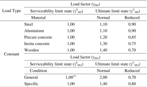
Table 1. Load Factor for Dead Load contains Self Load and Additional Dead Load
Load Type
Load factor (MS)
Serviceability limit state (SMS) Ultimate limit state (UMS)
Material Normal Reduced
Constant Steel 1,00 1,10 0,90 Aluminium 1,00 1,10 0,90 Precast concrete 1,00 1,20 0,85 Insitu concrete 1,00 1,30 0,75 Wooden 1,00 1,40 0,70 Load factor (MA)
Serviceability limit state (SMA) Ultimate limit state (UMA)
Condition Normal Reduced
General 1,00(1) 2,00 0,70
Specific 1,00 1,40 0,80
Note(1): Serviceability load factor 1,3 are used for utility weight 2.2.Traffic Load
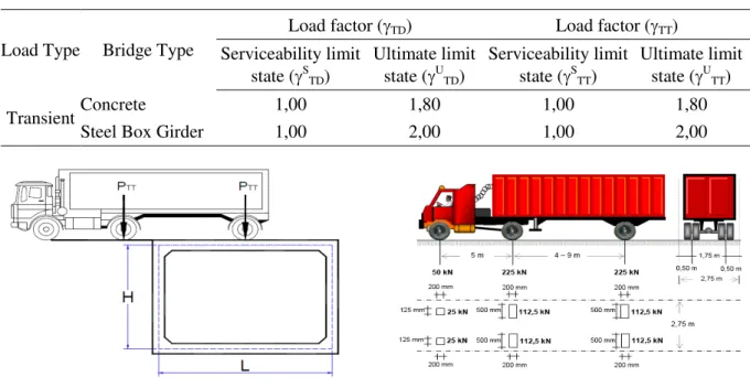
Traffic loads for bridge planning consist of "D" lane loads and "T" truck loads [1]. In determining the amount of traffic load must be multiplied by a factor of dynamic load of 40% for bridges with a span of less than 50 meters.
2.2.1.Lane Load "D". Lane load "D" consists of the evenly distributed load (BTR) and the line load (BGT). The intensity of BTR is regulated in an article 8.3.1 which has a quantity of q = 9.0 kPa for bridges with a maximum span of 30 meters, and a centered load of P = 49 kN / m. the loading model for the "D" lane load looks like in Figure 1.
Figure 1. “D” Lane Load.
2.2.2.Truck Load "T" (TT). In addition to the "D" load, there is another traffic load that needs to be taken into account, the load is a truck load "T”. The "T" load cannot be used together with the "D" load. Truck load will be very dominant for short span bridges, besides that truck load must also be
Intensity BGT=p kN/m Intensity BTR=q kPa Traffic direction BGT BTR
The 1st International Conference on Advanced Engineering and Technology - 2018
Table 2. Traffic Load Factor
Load Type Bridge Type
Load factor (TD) Load factor (TT) Serviceability limit state (STD) Ultimate limit state (UTD) Serviceability limit state (STT) Ultimate limit state (UTT) Transient Concrete 1,00 1,80 1,00 1,80
Steel Box Girder 1,00 2,00 1,00 2,00
Figure 2a. Position of Truck Axle Load. Figure 2b. Truck Axle Load 500 kN. 2.3.Vehicle Brake Load (TB)
In the bridge planning, the brake load must be taken from the largest values of: a. 25% of the designed weight of the truck axle or, b. 5% of the weight of the planned truck and evenly distributed lane load (BTR). Brake loads must be placed horizontally on all traffic lanes.
Figure 3. Brake Load Placement on Box Culvert.
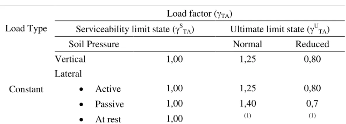
2.4.Soil Pressure Load (TA)
The nominal soil pressure coefficient must be calculated based on soil properties. Physical properties of soil must be obtained based on the results of measurements and soil testing in the field or
laboratory. Lateral soil pressure in the state of service limits is calculated based on the nominal values
of γs, c and Øf. Another factor in determining the amount of force due to lateral soil pressure on the box culvert is into the box and external load above the ground surface.
The 1st International Conference on Advanced Engineering and Technology - 2018
Table 3. Soil pressure load factors.
Load Type
Load factor (TA)
Serviceability limit state (STA) Ultimate limit state (UTA)
Soil Pressure Normal Reduced
Constant Vertical 1,00 1,25 0,80 Lateral Active 1,00 1,25 0,80 Passive 1,00 1,40 0,7 At rest 1,00 (1) (1)
Note(1): Lateral soil pressure at rest usually not included in ultimate limit condition
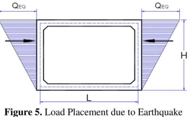
Figure 4. Lateral Soil Pressure. 2.5.Static Equivalent Earthquake Load
The earthquake load is taken as a horizontal lateral force which is determined based on the multiplication between the elastic response coefficient (Csm) and the equivalent structural weight (Wt) which is then divided by the response modification factor (Rd) [2].
𝐸𝑄 =𝐶𝑅𝑠𝑚𝑑 𝑥𝑊𝑡 (1)
2.6.Dynamic Soil Pressure Due to Earthquake Load
The lateral earthquake load due to dynamic soil pressure is calculated using the dynamic soil pressure coefficient (∆𝐾𝑎𝐺) as follows [3][4]: 𝜃 = 𝑡𝑎𝑛−1(𝐾 ℎ) (2) 𝐾𝑎𝐺 = 𝑐𝑜𝑠 2(𝜙′−𝜃) 𝑐𝑜𝑠2𝜃.{1+√(sin 𝜙′.sin(𝜙′−𝜃) cos 𝜃 } (3) ∆𝐾𝑎𝐺 = 𝐾𝑎𝐺− 𝐾𝑎 (4)
Thus, dynamic soil pressure is formulated:
𝑄𝐸𝑄= 𝐻. 𝑊𝑠. ∆𝐾𝑎𝐺 (5)
The 1st International Conference on Advanced Engineering and Technology - 2018
Figure 5. Load Placement due to Earthquake Dynamic Earthquake Pressure. 2.7.Soil Uplift Pressure
Uplift pressure is the lifting force of the building's base surface due to differences in building elevation. The amount of uplift pressure can be calculated by the following formula [5][6]:
𝑄𝑢𝑝𝑙𝑖𝑓𝑡 = 𝛾. 𝑍. 𝐴 (6)
Where: is water unit weight, Z is a delta elevation of groundwater table with slab, A is area which influenced by uplift pressure.
3.Methodology
The implementation phase of the research was carried out by controlling the ratio of reinforcement of existing culvert boxes. It then carried out the loading with the bridge load and obtained the reinforcement ratio plan.
3.1.Data Planning Specification
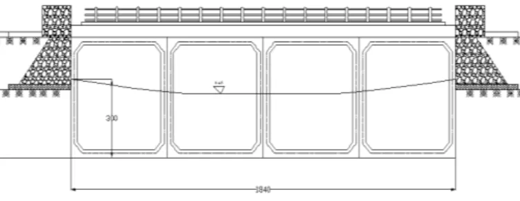
Figure 6. Box Culvert Dimension.
Main structure : Box Culvert
Dimension : 4,00 x 4,00 x 1,20 m
Bridge height : 4,80 m
Bridge width : 9,164 m
River width : 18,40 m
River depth : Groundwater table 3,00 m
Concrete compressive strength : 30 MPa
Steel bar U-40 tensile strength : 400 MPa
The 1st International Conference on Advanced Engineering and Technology - 2018
Figure 7. Cross section of existing bridge plan. Figure 8. Box culvert steel bar details.
3.2.Load input in Box Culvert
The loading analysis are based on SNI 1725-2016.
Self Weight QMS = 9,711 kN/m
Additional Dead Weight QMA = 1,60 kN/m
Lane Load “D” PTD = 68,6 kN
Truck Load “T” PTT = 315 kN
Pedestrian Load QTP = 2,5 kN/m
Wind Load TEW = 5,40225 kN/m
Earthquake Load TEQ = 12,915 kN
Vehicle Brake Load TTB = 2,99 kN
Soil Pressure Load on Box Culvert Wall Plate QTA1 = 10,32 kN/m
Soil Pressure Load on Box Culvert Wall Floor Plate QTA2 = 89,44 kN/m
Lateral Earthquake Load QEQ = -18,538 kN/m
Temperature Difference on Floor Plate ΔT = 12,5°C
Uplift Load due to Water = 55,2 kN/m
Uplift Load due to “D” = 16,56 ton
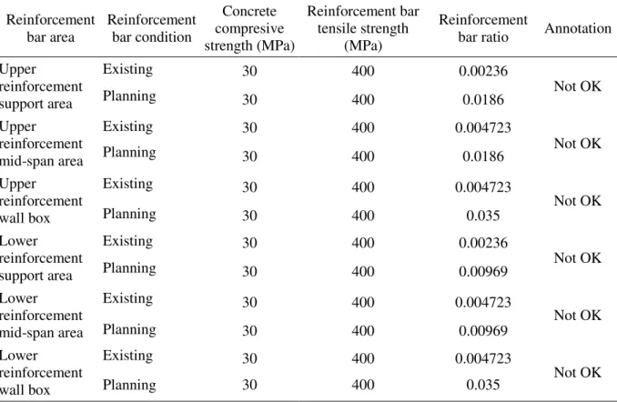
4.Results and Discussion
Analysis and comparison were carried out using the data in the existing box culvert. Where the results of the analysis focused on the flexural behaviour of the floor plate structure elements and the box culvert wall. As for the results of the analysis comparison according to Table 4.
The 1st International Conference on Advanced Engineering and Technology - 2018
Table 4. Traffic Load Factor.
Reinforcement bar area Reinforcement bar condition Concrete compresive strength (MPa) Reinforcement bar tensile strength (MPa) Reinforcement
bar ratio Annotation Upper reinforcement support area Existing 30 400 0.00236 Not OK Planning 30 400 0.0186 Upper reinforcement mid-span area Existing 30 400 0.004723 Not OK Planning 30 400 0.0186 Upper reinforcement wall box Existing 30 400 0.004723 Not OK Planning 30 400 0.035 Lower reinforcement support area Existing 30 400 0.00236 Not OK Planning 30 400 0.00969 Lower reinforcement mid-span area Existing 30 400 0.004723 Not OK Planning 30 400 0.00969 Lower reinforcement wall box Existing 30 400 0.004723 Not OK Planning 30 400 0.035 5.Conclusions
From the results of the analysis carried out on the existing box culvert as the main structure of the bridge on the arterial highway, it can be concluded as follows: The need for reinforcement of existing box culverts that are usually used as supporting structures (channels and culverts), does not meet the minimum requirements of strong box structure reinforcement against bridge construction loads in accordance with SNI 1725-2016 regulations. Based on the ratio of reinforcement requirements, the existing box culvert is at risk of experiencing flexural failure that occurs in almost all parts of the box culvert. It occurs both on the upper floor plate, the box wall and also the lower floor plate. There is an indication of fault analysis on the existing box culvert. It could be assumed that the top of the floor plate, either the top or bottom area is the foundation of the joint placement system. Which should be the support of the pinch system, this could be seen from the existing reinforcement ratio which shows that the field area has a ratio twice as large as the pedestal. The results of the reinforcement needs analysis for box structures with bridge loads show that the cross-section thickness of the box structure culverts on the slab area, whether the top or bottom parts need additional thickness, this could be seen from the reinforcement ratio that is almost close to the maximum ratio of reinforcement requirements in a section reinforced concrete. Whereas in the box culvert wall area, there is an over reinforcement so that the cross-section must be enlarged. Another alternative solution for box culverts that are able to withstand bridge loads other than by increasing the number of reinforcement and cross-section thickness by increasing the quality of the concrete box culvert and adding prestressed by using post tension system.
The 1st International Conference on Advanced Engineering and Technology - 2018
6.References
[1] National Standardization Institute, “Loading for bridges (SNI 1725 – 2016),” 2016.
[2] National Standardization Institute, “Bridge planning due to earthquake (SNI 2833 – 2013),” 2013.
[3] N. Mononobe and H. Matsuo, “The determination of earth pressure during earthquakes,” in Proc. Int. Conf. of the World Engineering, 1929.
[4] S. Okabe, “General theory of earth pressure,”J. Japanese Soc. Civ. Eng., vol. 12, no. 1, 1926. [5] U.S. Department of Transportation Federal Highway Administration, “Ground anchors and
anchored systems,” Washington D.C., 1999.
[6] American Concrete Institute, “Design considerations for environmental engineering concrete structures (ACI 350.4R-04),” Farmington Hills, 2004.