a
Corresponding author: [email protected]
Control of the probe influence on the flow field in LP steam
turbine
Michal Kolovratníka, Kukchol Yun, Ondej Bartoš
CTU in Prague, Department of Energy Engineering, Technická 4, Prague 6, 166 07, Czech Republic.
Abstract. For measuring the fine droplets properties in the wet steam expanding in the steam turbines the light extinction probes are usually used. The paper presents CFD modelling of the extinction probe influence on the wet steam flow field at the measurement position. The aim is to get a basic information about the influence of the flow field deviation on the measured data, in other words, of necessity to correct the measured data. The basic modelling procedure is described, as well asthe supposed simplifications and the factor considering the change in the steam density in the measuring slot of the probe. The model is based on the experimental data that were achieved during the developmental measurements in the steam turbine 1090 MW in the power station Temelín. The experimental measurement was done in the cooperation with the Doosan Škoda Power s.r.o.
1 Introduction
Experimental research of the liquid phase of the wet steam expanding in a steam turbine is a challenging problem. Despite the fact that the research was started in the seventies of the last century [1], commercial instrumentation is not yet available. Several institutions focusing on this issue (e.g. EdF, RWTH Aachen, ITSM Stuttgart, USST, EPRI, ETH Zürich) are carrying out an individual and a partially published research of the probes for the measurement of the fine “submicron” droplets formed by the nucleation and condensation as well as of probes for measuring the coarse “submillimeter” droplets formed in the flow part during the breakup of water films.
In the Czech Republic has been developed such an optical measuring system at Czech Technical University in Prague (CTU) and used for research and development purposes in the low pressure parts of the steam turbines in the classical and nuclear power plants. These measurements have been mostly done in close cooperation with Doosan Škoda Power s.r.o. (DŠP). For the fine droplets size distribution measurement the extinction probes are commonly used. Their development in line with global trends can be described by gradual minimization of the dimensions and application of the modern optical and electronic elements.
For many reasons the probe head diameter was gradually lowered by 60 % and the measuring slot was shortened to 20 % of the original length. This shortening is logically associated with increasing of the proportion of the wall influenced areas in the probe head measuring slot. Thus research has been started at CTU to assess the probe influence on the flow field in the steam turbines. Here is briefly presented dependence between the probe influence on the flow field and the acquired/processed
results of the wet steam wetness formed by the primary droplets. Research in further phases will be focused also on the issue of the influence of air flow for cleaning optical windows of the probe, the influence of probe‘s head shape and in the future also the probe head shape optimization.
2 The probe head shape design
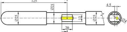
The measurement of the wet steam in the newly accessible (since the end of 2015) position behind the last but one stage of the low pressure part (LP) of the steam turbine 1090 MW the power station Temelín (ETE) required shape adjustment of the measuring head of the CTU extinction probe. Regarding the higher pressure level the length of the measuring slot was shortened from 50 to 20 mm [2]. The shape solution and dimensions of the used measuring head are shown in Fig.1. The measuring slot 20 x 13 mm is cut in a cylindrical body with the diameter of 21 mm. The shape is symmetrical, i.e. the volume is on sides limited by carrying ribs of the same shape. Parallel to the head axis a light beam of 4 mm diameter goes through. It is limited in the inlet and outlet by the glass windows. To enable the purging air flow the windows are recessed 0.7 mm below measuring slot upper and lower wall plane. Thus the geometrically active measuring volume in the measuring slot through which the wet steam flows is a cylinder with a diameter of 4 and length of 21.4 mm.
In an ideal case without the flow field being influenced by the probe the wet steam parameters in this cylinder would be identical with parameters in the same place without the probe presence.
3 Placement and positioning of the
probe in the steam turbine
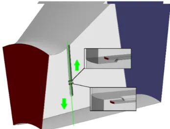
The placement of the extinction probe behind the rotor blade of the penultimate (L-1) stage of the LP part in the measuring plane A with an angle ~10° from the radial is given in Fig. 2. Basic manipulation with the probe head in the steam turbine is enabled by a cylindrical carrier with the diameter 35 mm and the length about 4.5 m. It allows traversing the head from the outside in a number of positions along the blade length z and turn it in the flow field (angle Dprobe) based on data from the pneumatic measurements (DŠP).
Fig. 2 Measuring plane in the steam turbine and scheme of probe orientation
In an optimal case the probe is in each position situated according to the corresponding angle Dprobe, but adjustment of the measuring slot to the “radial” angle
Hprobe is not possible. The flow field is influenced by the
probe head and also by the entire carrier.
4 Measuring method principle
For measuring, is used the dependence between a light attenuation and a dimensional structure of polydisperse system of droplets formed in the wet steam. It is expressed by known Lambert-Beer Law:
ଵ κ ቀ ூబ ூቁ ൌ గ ସܰ௩ ܳ ቀ గ ఒቁ ߮ሺܦሻܦଶ ಮ
݀ܦ (1)
where is the length of the measuring beam of the probe (or thickness of the wet steam lighted layer), I0 intensity
of light on the inlet of the measuring volume, I intensity of light on the outlet of the measuring volume, Nv is a number of droplets in the volume unit, Q(SD/O) coefficient of light extinction according to Mie theory [3], O is wavelength of light, D is droplets diameter,
M(D) normalized droplets size distribution.
Practically, in multispectral measuring of the light extinction, a beam of white light is used. The light intensity decreases as a result of light extinction on the droplets in the wet steam while passing through the probe measuring slot. The following spectral analysis of the light going out of the probe enables us to obtain the light intensity ratio decrease with dependence on wavelength I/I0 = f(Oi). The data processing is done for the selected number of discrete wavelengths i=1, 2,...k and thus a following set of equations:
ଵ κ ቀ ூబ ூቁൌ గ ସܰ௩ ܳ ቀ గ ఒቁ ߮ሺܦሻܦ ଶ ಮ
݀ܦ (2)
For a numerical solution of this system of the ill conditioned integral equations it is necessary to apply special methods. In the Department of Energy Engineering on CTU in Prague a regularisation method RNL [4] has been developed for this purpose. This method seems to be suitable for solving integral characteristics of polydispersions , such as a mean Sauter diameter D32 and a steam wetness y, from the measured
light extinction.
For polydisperse droplet system the steam wetness is described in the following relation:
1 3 3 ) ) ( " ' 6 ( 1 1 ) ( ' 6 max min max min
³
³
D D v D D p v dD D D N dD D D N yM
U
U
S
M
U
U
S
(3)where U’ and. U” is density of liquid and gaseous phase in the wet steam respectively.
5 Influencing parameters by the probe
In this phase of the research of probe influence on the flow field, which influences accuracy of the determined wetness y, two simplifying assumptions were chosen:
x Movement of the fine droplets and the carrying steam are identical.
x Droplets dimension do not change during the flow through the measuring slot of the probe, or they are identical with droplets dimension in the place of measurement without the probe influence.
When meeting these assumptions, wetness determined from the measurement can differ from the real wetness as a result of a change in wet steam density caused by the probe. Thus the CFD modelling described here focused on the change in steam density in passage through the slot of the probe, or the volume corresponding with the light beam.
6 CFD modelling of the probe influence
parameters in the free flow. Thus it is necessary to evaluate the probe influence on the flow field. To get information about the intensity of this influence in the probe measuring position and about the possibilities of its compensation for the data processing the CFD simulations were used.
The computational model for defining the probe influence includes the area between the rotor blades of L-1 stage and thestator blades of L-0 stage. The modelled volume is in Fig. 2. marked in red rectangle.
The probe with a symmetrical type of head and two ribs was inserted into modelled volume. During the measurements the probe was, accordingly to measurement procedure, gradually shifted along the traversing axis in the A plane, which is inclined from the radial by 10 degrees (Fig. 2 and 3).
Fig. 3 Computational domain
Computational mesh was prepared using ANSYS Meshing. Most of the computational model is meshed with hexahedral cells and only a part of the model with “complicated” geometry is meshed with tetrahedral or wedge cells.
At the inlet of the computational model the boundary condition of the „pressure–inlet“ type is set with the profile of total pressures and corresponding flow directions. For this adjustment the values of total pressures and direction vectors were used. They were measured behind the L-1 stage of ETE steam turbine by the DŠP team using pneumatic probes. At the outlet of the computational model the boundary condition of the „pressure–outlet“ type is adjusted with average static pressure before the L-0 stage. The set of boundary conditions is in Table 1.
Table 1: Survey of the boundary conditions
Inlet Outlet
Boundary condition Pressure inlet
Pressure outlet
Set values
Total pressure [Pa] Profile -
Static pressure [Pa] - 28800
Total temperature [K] 315 -
Turb. intens. [%] 5 -
For each position z along the blade, in which measurements were carried out using the extinction and pneumatic probe, an independent calculation was done. Altogether 18 calculations were carried out. In all calculations the two-equation k- turbulent model was used. As a working fluid in this phase of the research, water steam was chosen with the ideal gas properties. All calculations were implemented on ANSYS CFX 17.0.
As an example of results obtained the distribution of density on the transection of the calculation domain with a probe in one of the solved positions is shown in Fig. 4. From this figure it is obvious that density distribution in the probe measuring position is strongly distorted in comparison with balanced conditions in the inlet of the computational volume.
Figure 4. Example of density distribution
Results of implemented calculations were further processed in MATLAB.
7 Steam density in the probe slot
By processing the CFD calculation results of the wet steam density distribution was obtained in the probe measuring slot. As an example, a dimensionless steam density along the measuring beam U=f(") in one of the positions near the hub diameter of blading is shown in Fig. 5. This density profile is completed by mean value of density
U
(in blue).Figure 5 Dimensionless density in measuring slot
In fact the steam density is changing along the light beam. Nevertheless for the extinction measurements is not a fundamental problem. Providing the steam wetness is constant in the measuring volume, the same value of the light intensity ratio I/I0 occurs when the beam passes
through anenvironment with variable density U=f(") as it does during the passage through an environment with constant density
U
." " "
"
U U
³
0)
However, certain deviations of extinction against an ideal case with constant density can be caused by differences in density in cross sections of the beam. Thus in the modelled case in the cylindrical volume of the measuring beam with the diameter of 4 mm average density was defined in 16 control lines parallel to the probe axis. The differences in average density in these lines could be determined by the coefficient of variation Cv < 0.15 %. A detailed analysis of the issue goes beyond the paper´s intention. But it is possible to state here that the non-homogeneity of average density identified is acceptable from the viewpoint of influence on results obtained from extinction measurements. At the same time, space opens here for further research focused on optimization of the measuring beam diameter in extinction probes, or looking for the dependence between the beam diameter and the influence of density non-homogeneity on measured extinction.
8 Probe influence
An important finding from the results of CFD calculations is confirmation of the assumption that average steam density in the probe measuring beam is not generally identical with the steam density in the measuring point uninfluenced by the probe [5]. This fact has been so far considered in the CTU procedure for extinction measurements by a simple correction that lowered the light intensity ratio I/I0 [6]. However, CFD
calculations provided more complex information.
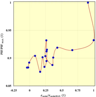
In each measurement positions along the blade height z the Probe Influence Factor (PIF) was defined as a ratio of average density in the place of measurement with the probe influence and without it. The dimensionless factor dependence on angle Hprobe in individual positions
is shown in Fig. 6.
Figure 6. Dimensionless dependence of PIF on Hprobe
angle
From Fig. 6 it is obvious that for the same values of radial angle Hprobe different PIF values were obtained in
various measurement positions. This confirms the fact that the solved issue of probe influence cannot be reduced only to modelling the flow influence in the direction of angle Hprobe. On the contrary, it is necessary to include
other influences in 3D flow field regarding interaction with the probe, with the carrier and limiting walls of the flow path.
Using the assumption that changes of density obtained by modelling of one-phase medium flow with ideal gas properties can be transmitted to conditions of real wet steam flow, a new calculation of steam wetness from extinction data corrected on defined change of density was carried out. In general it can be noted that, considering this correction, uncertainty of local wetness were in the range r3.5 %. Considering these uncertainties are practically identical with the “exactness” of wetness measuring according to VDI 2043 [7], where it is said, that measurement uncertainty for the optical method measurements of wetness caused by fine droplets is in the steam turbines can be expected in the range 10-15 %. It is obvious that the examined probe influence on the flow field cannot be neglected. On the contrary, it is necessary to design and implement a procedure for processing and application of corrections on the influence of flow field parameters by optical probes.
9 Conclusions
The research of wet steam liquid phase structure in the flow part of steam turbines requires invasive measurements using an optical, usually extinction, method. An effort to increase accuracy of measurements leads to gradual improvement of instrumentation and procedure. One of the unresolved problemsso far is the knowledge and possible correction of the probe influence on flow field parameters in the measurement area. Research was started based on numerical modelling with the aim to gain a basic idea of the importance of this influence. Using the knowledge of flow part geometry of LP part of steam turbine 1090 MW of ETE and experimental data obtained here from flow field research in the area between the L-1 and L-0 stages, the influence was modelled of CTU optical probe on the change of steam density in the measured volume. The changes of the yielded density in a number of positions along the blade show that the probe influence on flow field can, in the given modelled case, lead to relative uncertainty of measured local wetness up to r3.5 %. Thus the probe influence on the flow field cannot be neglected.
The follow-up works will be focused on research of: this influence in the flow conditions behind the steam turbine last stage, influence of various shape modifications of optical probe heads (one or two rib probes), optimization of the probe shape and measuring volume shape, and development correction method to eliminate the probe’s influence on the flow field.
Acknowledgement
References
1. Walters, P.T., Skingley, P.C.: An Optical Instrument for Measuring the Wetness Fraction and Droplet Size of Wet Steam Flow in LP Turbines, IMechE Proceedings: Steam Turbines for the 1980’s, London, 1979, 337-348
2. Kolovratník, M. Bartoš O.: EPJ Web of Conferences 114, 02056, (2016)
3. Bohren, C.F., Huffman, D.R.: Absorption and Scattering of Light by Small Particles. John Wiley & Sons, Inc., USA, 1998
4. Kolovratník, M.: Extinkní sondy pro mení v parních turbínách. Habilitaní práce, Praha, 2004 5. Walters, P. T.: Wetness and Efficiency Measurements in
L.P. Turbines with an Optical Probe as an Aid to Improving Performance. Transactions of the ASME, Journal of Engineering for Gas Turbines and Power, 1987, January, Vol. 109, 85-91
6. Petr, V., Kolovratník, M.: Heterogeneous Effects in the Droplet Nucleation Process in LP Steam Turbines – Proceedings: 4th European Conference on Turbomachinery, Firenze-Italy, 2001, pp. 783-792 7. VDI Richtlinien - VDI 2043 Measurement of Steam