Hand Controlled Mouse Pointer: A Typical
Wireless Handy Device
Thomas P Rajan1, Akhil C S 2, Ashik Sulaiman3, Thomas P J4
Assistant Professor, Dept. of EEE, Mar Athanasius College of Engineering, Kothamangalam, Kerala, India1
UG Student, Dept. of EEE, Mar Athanasius College of Engineering, Kothamangalam, Kerala, India2
UG Student, Dept. of EEE, Mar Athanasius College of Engineering, Kothamangalam, Kerala, India3
UG Student, Dept. of EEE, Mar Athanasius College of Engineering, Kothamangalam, Kerala, India4
ABSTRACT:The Hand Gesture Controlled Mouse Pointer, mapping Hand Gestures most intuitive communication gesture, to communicate with computers. Developments in the field of communication have enabled computer commands being executed using hand gestures communicating with computer involves use of touch screens, wireless/wired mouse along with keyboards. The aim of the project is to work with accelerometers and translate the motion of the hand into various applications in a virtual interface.It is most intuitive for us to use things based on our hand motions, as they form a very basic form of communication, signaling and gesturing. In order to translate these motions into the virtual world we use the accelerometer sensors.The orientation of accelerometer with the ground tells us the orientation our hand is in because of the components of gravity. The most commonly used hand motion control in a computer interface is that of a mouse. We have translated very normal gesturing of the hand into the motion of the pointer of the mouse. The mouse will be a hand mounted device that maps the movement of the users hand onto the computers mouse pointer, having all the standard functionalities as that of a computer mouse, left, right, middle click.Unique combination of finger movements that are very similar to the current mouseusage behaviorally would represent each of these.
KEYWORDS: Arduino, Accelerometer, Bluetooth module, Python .
I.INTRODUCTION
II
.
HARDWARE DESCRIPTIONIt consists of an accelerometer for sensing the movement, a bluetooth module for transmission, an Arduino as a controller, Switches, voltage regulator
A. ARDUINO
Arduino is open-source hardware. Most Arduino boards consist of an Atmel 8-bit AVR microcontroller (ATmega8, ATmega168, ATmega328, ATmega1280, ATmega2560) with varying amounts of ash memory, pins, and features. The boards use single or double-row pins or female headers that facilitate connections for programming and incorporation into other circuits. These may connect with add-on modules termed shields. Multiple and possibly stacked shields may be individually addressable via an IC serial bus. The Arduino Nano is a small, complete, and breadboard-friendly board based on the ATmega328P (Arduino Nano 3.x). It has more or less the same functionality of the Arduino Duemilanove, but in a different package. It lacks only a DC power jack, and works with a Mini-B USB cable instead of a standard one.
Fig 1: Arduino nano
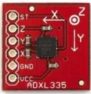
B. ACCLEROMETER
The ADXL345 is a small, thin, low power, 3-axis accelerometer with high resolution(13-bit) measurement at up to 16 g. Digital output data is formatted as 16-bit twos complement and is accessible through either a SPI (3- or 4-wire) or I2 C digital interface. The ADXL345 is well suited for mobile device applications. It measures the static acceleration of gravity in tilt-sensing applications, as well as dynamic acceleration resulting from motion or shock. Its high resolution (4 mg/LSB) enables measurement of inclination changes less than 1.0.The ADXL335 is a small, thin, low power, complete 3-axis accelerometer with signal conditioned voltage outputs. The product measuresacceleration with a minimum full-scale range of 3 g. It can measure the static acceleration of gravity in tilt-sensing applications, as well as dynamic acceleration resulting from motion, shock, or vibration.
Fig 2: ADXL335 Accelerometer
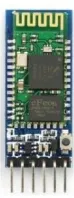
C. BLUETOOTH MODULE
SLAVE. The Role of the module (Master or Slave) can be congured only by AT COMMANDS. The slave modules cannot initiate a connection to another Bluetooth device, but can accept connections. Master module can initiate a connection to other devices.The user can use it simply for a serial port replacement to establish connection between MCU and GPS, PC to embedded system. The TXD and RXD are the transmitter and receiver pins respectively. The Vcc pin is for giving supply of 3.3-5 volts. Vcc and Gndof the module goes to Vcc and Gnd of Arduino. The TXD pin goes to RXD pin of Arduino and RXD pin goes to TXD pin of Arduino.
Fig 3: Bluetooth Module
D. SWITCHES
Like normal switches SMD switches are also used for the same function that in orderto control the current ow to the components. We use normal switches in the circuitto control the current ow or to turn on and off. When we use normal switches in the circuit it will consume more space and will be difficult to fabricate hand held devices which will be of small sizes. So in order to reduce the size and to make it in miniaturized form which is essential for the wearable devices. SMD switches are very small size and can be soldered easily on the PCB and will be much better to use
.
Fig 4: SMD Switch
E. AMS 117 VOLTAGE REGULATOR
Fig 4: AMS 117 Voltage Regulator
III.BLOCK DIAGRAM
Fig 5: Block Diagram of the system
Initially microcontroller check for the data from the accelerometer placedon the hand. If there is any movement it is recorded in the microcontroller and the corresponding command is sent through bluetooth transmitter. The python application program will execute the command..
IV.EXPERIMENTAL SETUP
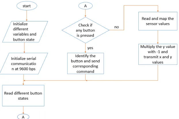
The flowchart of the transmitter side is
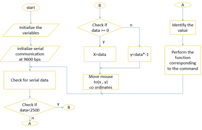
The flowchart of the receiver side is
Fig 7: Block Diagram of the Receiver
Fig 8: Circuit Diagram of the transmitter
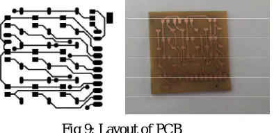
accelerometer sensor and two switches for left and right mouse button are made on a small pcb board and was attached on the ring, this assembly is connected to the arduino by wire strap.
Fig 9: Layout of PCB
The system consists of two parts.A mouse module and a base station which is a computer itself.The mouse module consists of accelerometer for position sensing, Bluetooth module,micro controller,switches and battery.The base station consists of bluetooth receiver, application using python. The 5v regulated power supply is obtained using 7805 regulator from a 9v rechargeable battery. This power is used to power all the sections of the transmitter. x and y pins of the sensor gives analog values according to the movement of the sensor These pins are connected to the 10 bit ADC of the Atmega 328 The value obtained from the ADC ranges from 0 to 1024 Bluetooth uses serial communication to communicate with microcontroller It uses the same power supply as that of the microcontroller Rx and Tx pins of Bluetooth are connected to the Tx and Rx pins of the microcontroller respectively Data transfer takes place at a baud rate of 9600 bps Operates at 2.4GHz Mapped sensor values and other commands are transmitted to the computer using this Bluetooth module Sensor values from ADC ranges from 0 to 1024 Values transmitted to the application is (sensor value 370) Max value obtained when sensor is moved to left is -78 Max value towards right is 68 For y axis max value obtained when sensor is moved up is 71 And max value when sensor is moved down is -80. X co-ordinate of the screen range from 0-1366 Y co-ordinate of the screen ranges from 0-768 Xpin readings from the sensor are mapped from [-78, 68] to [0,1500] Ypin readings are mapped from [-80,71] to [0,900] All the x values are transmitted as positive integers. All the y values are transmitted as negative integers So the mapped y values are then multiplied by -1. In the application program that is python all the positive values are identified as x coordinates of the screen and negative values are identified as y coordinates. Then the mouse pointer is moved to the required co-ordinate on the screen
V. RESULT
The parts labelled are 1-Accelerometer 2-Mouse left click 3-Mouse right click 4-Switch for volume up 5-Switch for volume down
Remaining switches are for arrow keys.
The screen recording during the system operating is as
Fig 11: Before hand movement
VI.CONCLUSION
Technologies developed based on gesture are now really affordable and converged with familiar and popular technologies like TV, large screen. It’s ubiquitous and non-intrusive as we can install a camera or remote with the TV. From this paper we can see the trends of gesture controlled communication systems. Easing of the technology use, affordability and familiarity indicate that gesture based user interface can open new opportunity for elderly and disable people. There will be more elderly people and fewer younger ones to care for them. So we need to invest much more heavily in Assistive Living solutions. The research a hand gesture controlled communication aid for elderly and disabled people can be a significant task for future. The two important aims of the research are to identify the different gestures of elderly and disabled people for communication and to design a rich augmented-reality interface for communication
REFERENCES
[1] Sohel Ahmed, Mohammed Abdullah Zubair, IrshadBasha Shaik, “Accelerometer based Wireless Air Mouse using Arduino Micro-controller Board”, Global Conference on Communication Technologies (GCCT 2015)
[2] Volkhardt, M., Mueller, S., Schroeter, C., Gross, H.-M., “Playing hide and seek with a mobile companion robot” Humanoid Robots (Humanoids), Eleventh IEEE-RAS International Conference, 2011.
[3] Rafiqul Zaman Khan and Noor Adnan Ibraheem ,” HAND GESTURE RECOGNITION: A LITERATURE REVIEW”, International Journal of Artificial Intelligence & Applications (IJAIA), Vol.3, No.4, July 2012
[4] Kenneth Sabir, Christian Stolte, Bruce Tabor, Sean I. O’Donoghue “The Molecular Control Toolkit: Controlling 3D Molecular Graphics via Gesture and Voice”, Biological Data Visualization (BioVis), 2013 IEEE Symposium, 2013
[5] M.Jain, Aditi, A.Lohiya, M.F.Khan, A Maurya, “Wireless Gesture Control Robot: an Analysis”,International Journal of Advanced Research in Computer and Communication Engineering Vol. 1, Issue 10, December, 2012.
[6] A. Nayyar, H. Lenka, “Design and Development of Wrist-Tiltbased Pc Cursor Control Using Accelerometer”,International Journal of Computer Science, Engineering and Applications 08/2013; 3(4):67-74. DOI: 10.5121/ijcsea.2013.3407.
[7] A.S.Ponraj, E.N.Daniel“AWireless Gesture Controlled Human Computer Interface”,International Journal of Engineering Technology and Computer Applications Vol.2, No.1, Apr 2012
[8] Gesture Tek, http://www.gesturetek.com, Available at http://www.gesturetek.com, 2009.
[9] Bainbridge, R., Paradiso, J.A. “Wireless Hand Gesture Capture through Wearable Passive Tag Sensing “ International Conference on Body Sensor Network, 2011, published by IEEE.
[10] Lombardi, A.; Ferri, M.; Rescio, G.; Grassi, M.; Malcovati, P., "Wearable wireless accelerometer with embedded fall-detection logic for multisensor ambient assisted living applications," Sensors, 2009 IEEE, vol., no., pp.1967, 1970, 25-28 Oct. 2009.
[11] Swapnil Badgujar, GourabTalukdar”, Hand Gesture Recognition System”, International Journal of scientific and Research Publications, Volume 4, Issue 2, February 2014, ISSN 2250-3153