New test of the dynamic theory of neutron diffraction by a
moving grating.
Maxim Zakharov1, 2,*,Alexander Frank1,German Kulin1, and SemyonGoryunov1
1FLNP, JINR, Joliot-Curie 6, Dubna, Moscow region, Russian Federation, 141980 2MIPT, Institutskiy per. 9, Dolgoprudny, Moscow Region, Russian Federation, 141701
Abstract. Recently, multiwave dynamical theory of neutron diffraction by a moving grating was developed. The theory predicts that at a certain height of the grating profile a significant suppression of the zero-order diffraction may occur. The experiment to confirm predictions of this theory was performed. The resulting diffracted UCNs spectra were measured using time-of-flight Fourier diffractometer. The experimental data were compared with the results of numerical simulation and were found in a good agreement with theoretical predictions.
1.
Introduction
Diffraction of neutron waves, like most other neutron-optical phenomena, has been considered for a long time from the point of the demonstration of the wave properties of a neutron and for the test of the predictions of stationary quantum mechanics. At the same time, it is known that neutron optics acquires new qualities in the cases when any parameters describing the interaction of a neutron beam with objects begin to depend on time. Nonstationary actions on a neutron wave allow variate significantly its characteristics such as the energy spectrum, phase, spin, intensity, direction of propagation, etc.
Neutron diffraction under certain conditions can also be considered as a nonstationary phenomenon. It was shown [1-3] that in the case of an absorbing or a phase grating moving across a monochromatic beam of ultracold neutrons (UCN), the grating can serve as a quantum modulator of a transmitted wave and the spectrum of neutrons passed through it is discrete.
The phenomenon of neutron diffraction on a moving grating has found its application in experiments on the test of the weak equivalence principle for a neutron [4]. The continuation of this investigation [5-7] and recent theoretical results [8] required a more rigorous investigation of the UCN spectra after diffraction by a moving grating.
2.
Theory of neutron diffraction from a moving grating
The problem of diffraction on a moving grating can be resolved in the coordinate system where the grating is at rest (fig 1b). In the laboratory coordinate system (fig 1c) the neutron energy is quantized, energy spectrum consists of discrete lines, and the neighboring lines of the spectrum differ by a value . The frequency is determined by the velocity V and the period d of the lattice .
Fig.1.Schemes of neutron diffraction on a grating: a – the grating at rest, ; b – the coordinate system moves together with the grating, ; c – moving grating in the laboratory coordinate system, .
*Corresponding author: [email protected]
2
d V
/
0 n
'
n
In Refs. [1-3], neutron diffraction from the moving grating was considered within the framework of the kinematic theory. An essential disadvantage of this theory is the fact that it is valid only for thin gratings where there is no any mutual effect of waves of different diffraction orders. To describe diffraction on real gratings, a more rigorous dynamic theory should be used.
The dynamic theory of diffraction developed in [8] is based on the method of slowly varying coupled amplitudes of wave functions. It takes into account the mutual effect of waves of different orders in the process of penetration of neutrons into the three-dimensional phase grating and is based on the solution of the Schrödinger equation in the
coordinate system where the grating at rest:
2
r r r 0
( ) k ( ) ( )
(1)
where – the Laplace operator, k– neutron wave number in vacuum, (r) = 4N(r)b(r), N(r)– nuclear density, b(r) the coherent scattering length of neutrons in the medium. Periodic in the range 0 zh function (x) is represented in the form of the series:
, (2)
where gn = ng0,g0 = 2/d,n = 0, 1, 2, … - integer numbers, and
. (3)
The zero Fourier amplitude 0 determines the value of the average refractive index of the gratingne = (1 0/k2)1/2 in the layer of thickness h.
The solution of Schrödinger equation in the range 0zh, in view of (2) and (3), is represented in the form of the
sum of Bloch functions with the amplitudes m(z) depending on the vertical coordinate z:
, (4)
where the projections of the wave vectors
mx 0x V m
q k k g , 2 1/2
0z 0z 0
q (k ) . (5)
Substituting (3) and (4) into (1) and equating terms with the same exponents, the following infinite system of coupled second-order differential equations was obtained:
0 0 2 2 0 2n n m n m m m z m dz d iq dz
d , (6)
where
)]
(
2
[
m V 0xm
m
g
g
k
k
. (7)The solution of system (6) is a rather laborious task. However, it is substantially simplified if the second derivatives in this system are neglected. As shown in [4], under conditions corresponding to real experiments, such approximation does not lead to significant errors. As a result, the following system of truncated differential equations of the first order was obtained:
0n n m n
m m
m i i
dz
d , (8)
where m = m/2q0z,n = n/2q0z. The system (8) should be supplemented by the following boundary conditions:
0(z = 0) = 1, m0(z = 0) = 0.
The coefficients m in (8), and, thereby, the functions m(z), depend on the velocity of the grating Vgr, the horizontal projection of the neutron velocity V0x, the grating period d and the diffraction order m. They are zero for both at m = 0 and under the Bragg condition 2(kVk0x) = gm. The system (8) is solved numerically.
3.
Experiment
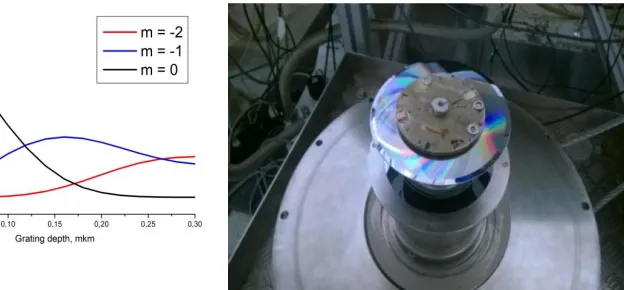
One of the predictions of the dynamic theory of diffraction [8] is that at a certain height of the grating profile a significant suppression of the zero-order diffraction may occur with a corresponding increase in the intensity of the lines of other orders (Fig.2). The aim of the experiment was to confirm this prediction. The experiment was performed at the PF2 UCN source of the Laue-Langevin Institute (Grenoble, France). As in the previous experiments [3- 7], a rotating grating was used instead of linearly moving grating (Fig. 3). The grating was prepared on the surface of a silicon disk. Radial grooves were made in the peripheral region of the disk. Two gratings were used. New grating (Grating 1) with
84000 grooves and the depth of 0.22 μm was specially manufactured for this experiment. Grating 2, with 94500 grooves
and the depth of 0.14 μm was the same as in experiment [7].
( ) exp( )
n
x n ig xn
1
0
( )exp( ) d
n d x ig x dxn
0 ( , ) m( )exp[ ( mx z )]
m
x z z i q x q z
Ultracold neutrons were fed to the entrance chamber through the UCN neutron guide and, after several reflections, fell down the annular channel with the lower section closed by a monochromator, which is a five-layer Ni-Ti neutron interference filter (NIF) [9]. To suppress the background of neutrons with energies higher than the effective potential of nickel, the filter-monochromator was combined with a multilayer “superwindow” filter [10]. Two NIFs with maximum of resonant transmission at 107 (NIF1) and 115 neV (NIF2) and FWHF 4 neV were used. The neutron spectrum formed by the filter-monochromator and transformed by the moving grating was measured using time-of-flight Fourier spectrometry technique [11].
Fig. 4.Time-of-flight Fourier spectrometer: general view (left) and its upper part (right). 1 - feeding neutron guide, 2 - entrance chamber, 3 - annular corridor, 4 - filter-monochromator, 5 - grating, 6 - rotor of the Fourier modulator, 7 - vertical glass guide, 8 -
detector, 9 - vacuum vessel.
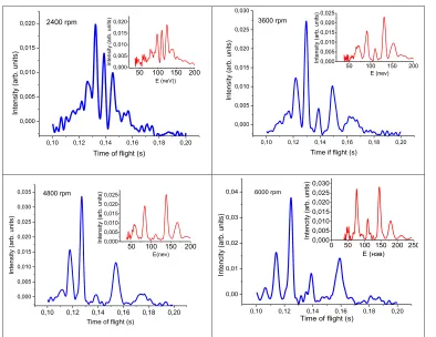
The measurements were done for different frequencies of the grating rotation from 2400 to 6000 rpm. In Fig.5 the results of the time of flight measurements of the diffraction spectra for the grating 1 and NIF1 are displayed. It is clearly seen in this picture that intensity of the zeroth diffraction order decreasing when the rotation speed is increasing from 2400 to 4800 rpm but increasing again for the rotation frequency 6000 rpm. To compare spectra formed by grating 1 and grating 2, the measurements with the grating 2 and NIF 1 have been also made with the rotation frequency 4800 (See Fig.6).
The measurement with grating 1 were repeated with NIF2 after some modification of the experimental installation (fig. 7). The results of this measurement were compared with the results of detailed calculation. To do that a computational-mathematical model of the experiment was created. The model includes a numerical calculation of the spectrum of UCN transmitted through a rotating radial grating using formalism of dynamic theory of neutron diffraction on moving grating [8], as well as a Monte Carlo simulation of the process of measuring of the neutron spectrum obtained after diffraction.
Fig.2.The dependence of the diffraction orders intensities on the depth of grooves at the grating rotation frequency f= 4800 rpm.
0,10 0,12 0,14 0,16 0,18 0,20 0,000 0,005 0,010 0,015 0,020
50 100 150 200
0,000 0,005 0,010 0,015 0,020 Inte nsity ( arb . un its)
Time of flight (s) 2400 rpm
Intensity (a
rb. units)
E (neV))
0,10 0,12 0,14 0,16 0,18 0,20 0,000 0,005 0,010 0,015 0,020 0,025 0,030
50 100 150 200 0,000 0,005 0,010 0,015 0,020 0,025 Intens ity (arb. un its)
Time if flight (s) 3600 rpm Int en sity (a rb . u nits) E (nev)
0,10 0,12 0,14 0,16 0,18 0,20
0,000 0,005 0,010 0,015 0,020 0,025 0,030 0,035
50 100 150 200
0,000 0,005 0,010 0,015 0,020 0,025 Intens ity (arb. un its)
Time of flight (s) 4800 rpm
Intensity (arb.
uni
ts)
E(nev)
0,10 0,12 0,14 0,16 0,18 0,20 0,00
0,01 0,02 0,03 0,04
0 50 100 150 200 250 0,000 0,005 0,010 0,015 0,020 0,025 0,030 Inte ncity ( arb . un its)
Time of flight (s) 6000 rpm Inte ncity ( arb . un its)
E (нэв)
Fig. 5.Time of flight spectra appeared at neutron diffraction by a moving grating 1. In the inset the same plotted in the energy scale
0,10 0,12 0,14 0,16 0,18 0,20 0,00
0,01 0,02 0,03 0,04
50 100 150 200 0,000 0,005 0,010 0,015 0,020 0,025 Intens ity (arb. un its)
Time of flight (s)
Intensity (
arb.
uni
ts)
Energy (neV)
0 50 100 150 200 250
0,0 0,2 0,4 0,6 0,8 1,0 1,2 1,4 In te nsit y (a rb . u nits ) Energy, neV Experiment Theory
Fig. 6. Time of flight spectrum appeared at neutron diffraction by a moving grating 2. In the inset the same plotted in the energy scale
Fig.7 Comparison of the measured spectrum with the theoretical model
correspondent line in fig.7. Notice that the width of the line in the spectrum depends on the initial horizontal velocities and additional spreading due to this effect is proportional to the number of the diffraction order.
Conclusion
The experiment to test the dynamic theory of neutron diffraction by a moving grating was performed. The resulting diffracted UCNs spectra were measured using time-of-flight Fourier diffractometer. The experimental data were compared with the results of numerical simulation and were found in a good agreement with theoretical predictions.
References
1. A. I. Frank and V. G. Nosov, Phys. Lett. A 188, 120 (1994).
2. A. I. Frank, S. N. Balashov, I. V. Bondarenko et al., Phys. Lett. A 311, 6 (2003). 3. A. I. Frank, P. Geltenbort, G. V. Kulin et al., JETP Lett. 81, 427 (2005). 4. A. I. Frank, P. Geltenbort, M. Jentschel et al., JETP Lett. 86, 225 (2007). 5. A. I. Frank, P. Geltenbort, M. Jentschel et al., NIM A. A 611, 314 (2009). 6. G.V. Kulin, A.I. Frank, S.V. Goryunov,et al. NIM A 79238 (2015) 7. G.V. Kulin, A.I. Frank, S.V. Goryunov, et al.Phys. Rev. A 93, 033606(2016) 8. Bushuev V. A., Frank A.I., Kulin G.V., JETP, 122(1) (2016) 32
9. I. V. Bondarenko, V. I. Bodnarchuk, and S. N. Balashov. Phys.At. Nucl. 62, 721 (1999). 10. A. I. Frank, S. V. Balashov, V. I. Bodnarchuk et al., Proc. SPIE3767, 360 (1999).